EP0244060B1 - Mastkonstruktion für Arbeitsplattform - Google Patents
Mastkonstruktion für Arbeitsplattform Download PDFInfo
- Publication number
- EP0244060B1 EP0244060B1 EP87301690A EP87301690A EP0244060B1 EP 0244060 B1 EP0244060 B1 EP 0244060B1 EP 87301690 A EP87301690 A EP 87301690A EP 87301690 A EP87301690 A EP 87301690A EP 0244060 B1 EP0244060 B1 EP 0244060B1
- Authority
- EP
- European Patent Office
- Prior art keywords
- mast
- mast section
- section
- sections
- secured
- Prior art date
- Legal status (The legal status is an assumption and is not a legal conclusion. Google has not performed a legal analysis and makes no representation as to the accuracy of the status listed.)
- Expired
Links
- NJPPVKZQTLUDBO-UHFFFAOYSA-N novaluron Chemical group C1=C(Cl)C(OC(F)(F)C(OC(F)(F)F)F)=CC=C1NC(=O)NC(=O)C1=C(F)C=CC=C1F NJPPVKZQTLUDBO-UHFFFAOYSA-N 0.000 title claims description 15
- 238000010276 construction Methods 0.000 title description 4
- 229910052782 aluminium Inorganic materials 0.000 claims description 21
- XAGFODPZIPBFFR-UHFFFAOYSA-N aluminium Chemical compound [Al] XAGFODPZIPBFFR-UHFFFAOYSA-N 0.000 claims description 21
- 239000000463 material Substances 0.000 claims description 5
- 229910052751 metal Inorganic materials 0.000 claims description 3
- 239000002184 metal Substances 0.000 claims description 3
- 229920003023 plastic Polymers 0.000 claims description 3
- 239000004033 plastic Substances 0.000 claims description 3
- 239000004411 aluminium Substances 0.000 claims description 2
- 238000006073 displacement reaction Methods 0.000 claims description 2
- 239000004744 fabric Substances 0.000 claims description 2
- 230000000295 complement effect Effects 0.000 description 6
- 238000004519 manufacturing process Methods 0.000 description 6
- 238000001125 extrusion Methods 0.000 description 5
- 238000005452 bending Methods 0.000 description 2
- 239000012530 fluid Substances 0.000 description 2
- 239000004677 Nylon Substances 0.000 description 1
- 238000006243 chemical reaction Methods 0.000 description 1
- 229920006178 high molecular weight high density polyethylene Polymers 0.000 description 1
- 238000000034 method Methods 0.000 description 1
- 229920001778 nylon Polymers 0.000 description 1
Images

Classifications
-
- B—PERFORMING OPERATIONS; TRANSPORTING
- B66—HOISTING; LIFTING; HAULING
- B66F—HOISTING, LIFTING, HAULING OR PUSHING, NOT OTHERWISE PROVIDED FOR, e.g. DEVICES WHICH APPLY A LIFTING OR PUSHING FORCE DIRECTLY TO THE SURFACE OF A LOAD
- B66F11/00—Lifting devices specially adapted for particular uses not otherwise provided for
- B66F11/04—Lifting devices specially adapted for particular uses not otherwise provided for for movable platforms or cabins, e.g. on vehicles, permitting workmen to place themselves in any desired position for carrying out required operations
Definitions
- This invention relates to movable pedestal type scaffold units of the general type shown in U.S. Patent No. 4,397,373, issued August 9, 1983, U.S. Patent No. 4 592 447, issued June 3, 1986, and U.S. Patent No. 4 258 825 of March 31, 1981.
- Personnel lifts of the pedestal type exemplified by the above patents typically have an upright mast mounted on a relatively small base member, and a work cage mounted on the mast for vertical movement.
- the mast of US Patent 4,397,373 comprises a plurality of side-by-side parallel frame sections arranged to extend vertically relative to each other.
- these mast sections comprise opposed vertical extruded aluminum channels connected together by a plurality of cross pieces.
- the weight of a scaffold unit of this type is an important consideration since these units must be moved from place to place and loaded onto and off trucks by the workmen using the scaffolds.
- the cost of construction is also an important consideration in enabling the scaffold units to be sold at a price that can be afforded by purchasers.
- the weight of the mast sections is, of course, also related to the cost of manufacture in that the more the weight, the more the material that is used in the mast.
- the mast of US Patent 4,592,447 comprises a plurality of telescopically arranged aluminum extrusions. Again, such a mast is relatively heavy and expensive to manufacture. In particular, aluminum extrusions require costly dies for the extrusion process and the wall thickness of an extruded column must inherently be relatively great. The outermost mast sections in particular will have considerable weight and be quite high in manufacturing cost.
- US Patent 4258825 describes a pedestal-type scaffold unit with a work-platform mast made of telescopically-nested metal sections, with means comprising a cable and pulleys for extending the mast. Each section has a collar at its top end to guide the section within it.
- the present invention provides a pedestal scaffold having a base member on which is mounted a mast bearing a work platform and comprising a plurality of telescopically nested mast sections which are substantially rectangular in cross-section, with means for extending the mast upwardly by relative telescopic displacement of the mast sections, characterised in that at least some said mast sections are thin-walled tubes of sheet metal with rounded corners, each being provided with at least one stiffening rib extending longitudinally in a side wall thereof, a set of inwardly projecting corner slide blocks having respective inner surfaces complementing the shape of and adapted to slide against outer corner surfaces of an inwardly adjacent mast section and a set of outwardly projecting corner slide blocks having respective outer surfaces complementing the shape of and adapted to slide against inner corner surfaces of an outwardly adjacent mast section.
- the majority of the mast sections are preferably of thin-walled sheet aluminium. Preferably there is vertical stiffening rib on each side of the section.
- the slide blocks which preferably are at the upper and lower ends of the mast sections and at the four corners of the mast sections, and have mast-engaging surfaces complementary in shape to the rounded corners of the mast sections, may be made of plastics material.
- chains and straps fit into the narrow spaces between the mast sections for raising and lowering of the mast sections.
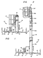
- Fig. 1 shows a movable pedestal scaffold 10 having a base member 11 with wheels 12 at either end of the base member.
- outriggers 13, each with a vertically adjustable ground engaging member 14, are attachable to the base member 11 to provide an extended area of support for the unit.
- a vertical mast 16 extends upwardly.
- the mast 16 comprises six telescoped mast sections 16a-f, the outermost mast section 16a being mounted on the base member 11.
- a work cage 17 is mounted, by cantilever arm 18, to the upper end of the innermost mast section 16f.
- the work cage is spaced horizontally from the innermost mast section 16f and extends downwardly from the upper end of the mast section 16f and along one side of the mast.
- a ladder 19 on the base member 11 enables a workman to climb up to the work cage when the cage is at its downwardly retracted position of Fig. 1.
- apparatus 20 will include a hydraulic reservoir, a fluid pump and batteries for driving the pump.
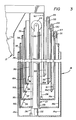
- FIG. 3 shows in simplified form the apparatus for vertical extension of the sections 16b-f of mast 16.
- a extensible fluid-operated ram 21 is vertically disposed centrally of the mast 16, with its piston member 22 secured to the lower end of the outermost mast section 16a and with its cylinder member 12 secured to the lower end of the next innermost mast section 16b.
- a sprocket 24 is mounted on the upper end of ram 21 and chain 26 extends around sprocket 24 with one end of the chain 26 being connected to the lower end of the outermost mast section 16a and with the other end of the chain being connected to the lower end of mast section 16c.
- Additional sprockets 27, 28 and 29 are mounted on the upper ends of mast sections 16c, 16d and 16e, respectively.
- Chain 31 extends from the upper end of mast section 16b up over sprocket 27 and then down to the lower end of mast section 16d.
- chain 32 runs from the upper end of mast section 16c upward over sprocket 28 and down to the lower end of mast section 16e, while chain 33 runs from the upper end of mast section 16d up over sprocket 29 and down to the lower end of the innermost mast section 16f.
- the lifting forces exerted by the chains on the mast sections are necessarily offset from the central axis of the mast.
- the offset forces are balanced to a considerable degree by the weight of the work cage and its occupant which are also offset from the central axis of the mast, but on the side of the mast opposite from the chain mechanism.
- the chains and sprockets described above are preferably doubled for the stages to equalize loading forces and to provide backup support in the event of a chain failure.
- a plurality of fabric straps 36, 37, 38 and 39 interconnect the mast sections on the side of the mast opposite to the chains described above, with each strap being secured to the upper end of a mast section and extending down to and around the lower end of the next innermost mast section and then being secured to the lower end of the then next innermost mast section.
- strap 36 is secured to mast section 16a, extends down around the lower end of mast section 16b and is secured to the lower end of mast section 16c.
- the mast 16 will retract downwardly with release of hydraulic fluid from the ram 21 causing mast secsection 16b to move downwardly.
- the weight of the work cage wil cause the other mast sections to lower as the various sprockets 24, 27, 28 and 29 move downwardly.
- the straps 36-39 merely follow the downward movement of the mast sections and bear no stress.
- the straps 36-39 will serve to prevent retraction of lower mast sections. For example, suppose mast section 16d were to hang up on some obstruction as it was moving downwardly. The lower end of mast section 16d would then be "fixed” against further downward movement. Since the upper end of the outermost mast section 16a is likewise fixed against vertical movement, straps 36 and 37 will support mast sections 16b and 16c and prevent them from moving downwardly. Chains 32 and 33 will likewise prevent any downward movement of the mast sections 16e and 16f above the hung-up mast section 16d.
- any mast section is externally prevented from retracting downwardly, the straps and chains will prevent all of the other mast sections from retracting.
- the use of straps as disclosed is very advantageous since they are strong, flexible and can fit easily into the very restricted spaces between the mast sections. In case of such a hang up, the operator can then cause the mast to extend upwardly so that the obstruction can be removed. After that, retraction can take place in a normal manner.
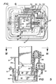
- Figs. 4-6 illustrate the details of the sections of the mast 12.
- Fig. 4 illustrates, in perspective, mast section 16c.
- mast section 16c is made from two identical U-shaped channels 41 and 42 formed from thin-walled sheet aluminum.
- personnel lifts have been built in accordance with the present invention with a 38 foot maximum platform height and using 5052 H32 sheet aluminum with a 0.060 inch wall thickness for the sheet aluminum mast sections.
- Each U-shaped channel 41 and 42 is formed with substantially rounded corners 43 and is deformed from the plane of the base side 44 of the channel to provide a stiffening rib 46 extending the full height of the channel.
- the legs 47 of the channel are also deformed from the planes of the legs to provide offset end portions 48 parallel to the planes of the legs.
- the two channel sections 41 and 42 are placed with the offset portions 48 adjacent to each other and are joined together by rivets 49 along the height of the mast section. The offset portions thus form a stiffening rib.
- An upper collar 51 preferably of cast aluminum, surrounds the upper end of the joined together sheet aluminum channels 41 and 42, the collar 51 having vertical flanges 52, to which the channels 41 and 42 are secured by rivets 53, and an outwardly projecting horizontal flange 54.
- the collar 51 protects the upper edges of the sheet aluminum channels and maintains the rectangularity of the mast section.
- the collar 51 supports sprocket 27 and provides a rigid member to which chains 32 are secured.
- the collar 51 provides a rigid member for attachment of strap 38.
- a similar, but inverted, lower collar 56 extends around the inside of the joined together sheet aluminum channels and is secured thereto by rivets 57.
- This collar likewise protects the lower edges of the channels 41 and 42, maintains the rectangularity of the mast section, and provides a rigid member for attachment to the strap 36 (not shown in Fig. 4) secured thereto.
- the lower collar 56 also provides a rigid member to which chains 31, 32 and 33 may be secured.
- Each of the aluminum sheet mast sections 16b-e has an upper and lower collar 51, 56 generally as described in connection with mast section 16c.
- the outermost mast section 16a has an upper collar 51 thereon, but no lower collar 56 is needed since the attachment of the mast section 16a to the frame member 11 serves the purpose.
- the preferred embodiment shown herein has an extruded aluminum tube as the innermost mast section 16f. Because of the relatively small cross-sectional modulus of this innermost mast section, a thicker walled aluminum sheet would be necessary to withstand the high bending stresses. Further, the mast was designed so that the innermost mast section has a 4 x 4 inch size which is a standard, commercially available aluminum extrusion, with a 1/8 inch wall thickness.
- the mast sections will range in height from about 7 feet for mast section 16a to about 51 ⁇ 2 feet for the innermost mast section 16f.
- the cross-sectional area of the mast sections ranges from about 9 x 12 inches for mast section 16a to 4 x 4 inches for the mast section 16f.
- the mast section 16c has a set of four plastic slide blocks 61 mounted on the upper end of the mast section, with one of the slide blocks being mounted at each of the four inside corners of the mast section and secured thereto, as by screws 62, the slide blocks being approximately 6 inches in height.
- Each slide block has an outer surface 63 of a shape complementary to the shape of the inside corner of the mast section to which it is secured and an inner surface 64 of a shape complementary to the shape of the outside corner of the next inner mast section 16d adjacent thereto.
- the slide blocks are made of UHMW (ultra high molecular weight) high density polyethylene.
- the slide blocks are placed at the corners of the mast sections where the mast sections are strongest and where the least amount of deformation will occur when the mast is under load.
- the rounded corners of the mast sections and the complementary shaped slide blocks serve to distribute the bearing pressure on the slide blocks and to distribute the force from the slide blocks onto a relatively large area of the thin-walled aluminum sheet mast sections.
- mast section 16c has a set of four slide blocks 66 mounted on the lower end of the mast section at the outside of each of the four corners.
- Slide blocks 66 each have an inner surface 67 of a shape complementary to the shape of the outside corner of mast section 16c to which it is mounted and an outer surface 68 of a shape complementary to the shape of the inner corner of the next mast section adjacent thereto.
- the shape of the slide blocks spreads the forces over a substantial area of the aluminum sheet instead of concentrating them at a sharp corner.
- the present invention provides a mast that is relatively light in weight and relatively inexpensive to manufacture because it is largely made out of thin walled aluminum sheet rather than thicker and considerably more expensive aluminum extrusions.
- the relatively large rectangular cross-section of the mast section provides for a very efficient distribution of material while providing a very rigid mast which will resist bending forces from the cantilever mounted work cage and torsional forces impared by reaction forces by a workman working to his side while in the cage.
Landscapes
- Engineering & Computer Science (AREA)
- Structural Engineering (AREA)
- Life Sciences & Earth Sciences (AREA)
- Geology (AREA)
- Mechanical Engineering (AREA)
- Movable Scaffolding (AREA)
Claims (10)
- Piedestalgerüst mit einem Basiselement (11), auf dem ein Mast (16) montiert ist, der eine Arbeitsplattform (17) trägt und eine Vielzahl von teleskopisch ineinandergeschachtelten Mastabschnitten (16a-f) umfaßt, die einen im wesentlichen rechteckigen Querschnitt aufweisen, mit Mitteln zum Verlängern des Mastes (16) nach oben durch relatives teleskopisches Verschieben der Mastabschnitte, dadurch gekennzeichnet, daß zumindest einige der genannten Mastabschnitte (16b-e) dünnwandige Rohre aus Blech mit gerundeten Ecken sind, wobei jede mit zumindest einer Versteifungsrippe (46) versehen ist, die sich longitudinal in einer Seitenwand davon erstreckt, sowie mit einem Satz nach innen vorragender Eck-Gleitklötze (61), die jeweils innere Oberflächen (64) aufweisen, welche zur Form von äußeren Eck-Oberflächen eines von innen angrenzenden Mastabschnitts (16b-f) komplementär sind und so ausgebildet sind, daß sie gegen diese gleiten, und mit einem Satz nach außen vorragender Eck-Gleitklötze (66), die jeweils äußere Oberflächen (68) aufweisen, welche zur Form von inneren Eck-Oberflächen eines von außen angrenzenden Mastabschnitts (16a-d) komplementär sind und so ausgebildet sind, daß sie gegen diese gleiten.
- Piedestalgerüst nach Anspruch 1, worin die genannten nach innen vorragenden Gleitklötze (61) vier Klötze umfassen, die an den jeweiligen Ecken (43) am oder nahe dem oberen Ende des Mastabschnitts (16b-e) montiert sind, und die genannten nach außen vorragenden Gleitklötze (66) vier Klötze umfassen, die an den jeweiligen Ecken (43) am oder nahe dem unteren Ende des Mastabschnitts (16b-e) montiert sind.
- Piedestalgerüst nach Anspruch 1 oder 2, worin die Wände der genannten zumindest einigen Mastabschnitte (16b-e) aus dünnem Aluminiumblech bestehen.
- Piedestalgerüst nach einem der vorhergehenden Ansprüche, worin zumindest einer der genannten Mastabschnitte (16a-f) zwei im wesentlichen identische longitudinale U-Profil-Kanäle (41,42) umfaßt, wobei jeder Kanal (41,42) parallele gegeneinander versetzte Endabschnitte (48) an den longitudinalen Rändern der Schenkel (47) des U aufweist, die beiden Kanäle (41, 42) einander gegenüberliegen und entlang der gegeneinander versetzten Endabschnitte (48) verbunden sind, sodaß die genannten verbundenen Endabschnitte (48) Versteifungsrippen bilden.
- Piedestalgerüst nach Anspruch 4, worin eine Basisseite (44) eines jeden Kanals (41,42) eine Deformation aus ihrer eigenen Ebene heraus aufweist, die eine Versteifungsrippe (46) schafft, welche sich entlang des Kanals (41,42) erstreckt.
- Piedestalgerüst nach einem der vorhergehenden Ansprüche, worin die Mittel zum Verlängern des Mastes (16) ein verlängerbares Hebewerk (2) umfassen, das an einem ersten, unteren Matabschnitte (16a) und an einem zweiten, nach innen an den ersten Mastabschnitt (16a) angrenzenden Mastabschnitt (16b) montiert ist und so betätigt werden kann, daß die genannten ersten und zweiten Abschnitte auseinanderbewegt werden können, sowie ein Kettenrad (27,28,29), das am oder in der Nähe des oberen Endes von zumindest einem Mastabschnitt (16c-e) montiert ist, und eine Kette (31,32,33), die um das Kettenrad (27,28,29) gezogen ist und am oder in der Nähe vom oberen Ende eines Mastabschnitts (16b-d) befestigt ist, der von außen an den genannten zumindest einen Mastabschnitt (16c-e) angrenzt, sowie am oder in der Nähe vom unteren Ende eines Mastabschnitts (16d-f), der von innen an den genannten zumindest einen Mastabschnitt (16c-e) angrenzt.
- Piedestalgerüst nach Anspruch 6, worin Mastabschnitte (16d-e) jeweils einen oberen Bundring bzw. Kragen (51) aufweisen, der sich um die Außenseite des oberen Endes des Mastabschnitts herum erstreckt und an diesem befestigt ist, sowie einen unteren Bundring bzw. Kragen (56), der sich um die Innenseite des unteren Endes des Mastabschnitts herum erstreckt und an diesem befestigt ist, wobei das Kettenrad (27,28,29) und die Kette (31,32,33) jeweils an den genannten Bundringen bzw. Krägen (51,56) montiert und gesichert sind.
- Piedestalgerüst nach Anspruch 6 oder 7, worin die genannten Kettenräder (27,28,29) und Ketten (31,32,33) gegen eine Seite des Masts (16) angeordnet sind, wobei an der gegenüberliegenden Seites des Masts (16) eine Vielzahl von Gewebsriemenelementen (36,37,38,39) vorhanden sind, wobei jedes Riemenelement (36,37,38,39) am oder in der Nähe des oberen Endes eines Mastabschnitts (16a-d) befestigt ist und sich zum unteren Ende eines innen angrenzenden Mastabschnitts (16b-e) hinunter und um dieses herum erstreckt, und am oder in der Nähe des unteren Endes des nächsten innen angrenzenden Mastabschnitts (16c-f) befestigt ist.
- Piedestalgerüst nach einem der Ansprüche 6, 7 und 8, worin die Mittel zum Verlängern des Masts (16) ein Kettenrad (24) einschließen, das auf einem oberen Ende des Teils des Hebewerks (2) montiert ist, das am zweiten Mastabschnitt (16b) montiert ist, sowie eine Kette (26), die um das genannte Kettenrad (24) gezogen ist, wobei die Kette (26) am einen Ende am ersten, unteren Mastabschnitt (16a) und am anderen Ende an einem Mastabschnitt (16c) befestigt ist, der innen an den zweiten Mastabschnitt (16b) angrenzt.
- Piedestalgerüst nach einem der vorangehenden Ansprüche, worin die genannten Gleitklötze (61,66) aus Kunststoffmaterial bestehen.
Applications Claiming Priority (2)
| Application Number | Priority Date | Filing Date | Title |
|---|---|---|---|
| US06/856,050 US4657112A (en) | 1986-04-25 | 1986-04-25 | Mast construction for pedestal scaffold |
| US856050 | 1986-04-25 |
Publications (3)
| Publication Number | Publication Date |
|---|---|
| EP0244060A2 EP0244060A2 (de) | 1987-11-04 |
| EP0244060A3 EP0244060A3 (en) | 1989-10-04 |
| EP0244060B1 true EP0244060B1 (de) | 1992-05-06 |
Family
ID=25322751
Family Applications (1)
| Application Number | Title | Priority Date | Filing Date |
|---|---|---|---|
| EP87301690A Expired EP0244060B1 (de) | 1986-04-25 | 1987-02-26 | Mastkonstruktion für Arbeitsplattform |
Country Status (5)
| Country | Link |
|---|---|
| US (1) | US4657112A (de) |
| EP (1) | EP0244060B1 (de) |
| JP (1) | JPS62276162A (de) |
| AU (1) | AU586534B2 (de) |
| DE (1) | DE3778751D1 (de) |
Cited By (1)
| Publication number | Priority date | Publication date | Assignee | Title |
|---|---|---|---|---|
| US10060142B2 (en) | 2013-12-09 | 2018-08-28 | Haessler Inc. | Vertically elevating mobile work platform |
Families Citing this family (54)
| Publication number | Priority date | Publication date | Assignee | Title |
|---|---|---|---|---|
| US4783934A (en) * | 1986-11-21 | 1988-11-15 | United Production Services, Inc. | Free-standing assembly and method for making same |
| FR2632621B1 (fr) * | 1988-06-10 | 1990-08-17 | Reel Sa | Mat telescopique permettant d'assurer le maintien et les manoeuvres d'une nacelle ou plateforme de travail dont les deplacements sont commandes par un pont roulant |
| DE8903568U1 (de) * | 1989-03-17 | 1990-04-19 | Ramani, Zyber, 1000 Berlin | Arbeitsbühne |
| CA2036617C (en) * | 1990-02-20 | 1996-04-23 | Mitsuhiro Kishi | Lifting apparatus |
| IE68595B1 (en) * | 1990-09-10 | 1996-06-26 | Burt Will Comp | A drive |
| US5115606A (en) * | 1990-09-24 | 1992-05-26 | Ingersoll-Rand Company | Extension cable for telescopic tower |
| AU651616B2 (en) * | 1990-10-08 | 1994-07-28 | Kajima Corporation | Process for constructing frame and erection |
| US5209433A (en) * | 1991-01-28 | 1993-05-11 | Brown & Root U.S.A., Inc. | Mobile rocket service tower |
| JP2652592B2 (ja) * | 1991-05-17 | 1997-09-10 | 日本スカイロボット株式会社 | 伸縮柱等の進退機構 |
| FR2717456B1 (fr) * | 1994-03-16 | 1996-05-03 | Cimm | Dispositif élévateur de personnel. |
| JPH11513651A (ja) * | 1995-10-23 | 1999-11-24 | アップライト,インコーポレイテッド | 可動ケージアセンブリを有する人員用リフト |
| US5803204A (en) * | 1995-10-23 | 1998-09-08 | Upright, Inc. | Personnel lift with clamshell cage assembly |
| US5718087A (en) * | 1996-05-02 | 1998-02-17 | The Will-Burt Company | Telescoping mast assembly |
| US6174124B1 (en) * | 1996-10-04 | 2001-01-16 | Crown Equipment Corporation | Load trays for personnel carrying vehicles |
| MXPA00002131A (es) * | 1997-09-08 | 2002-07-05 | Crown Equip Corp | Vehiculo para transporte de personal. |
| US6299336B1 (en) * | 1999-08-26 | 2001-10-09 | The Will-Burt Company | Low profile lift mounting arrangement for telescoping mast |
| US6375370B1 (en) * | 2000-02-10 | 2002-04-23 | Cam Guard Systems, Inc. | Temporary surveillance system |
| US20080100707A1 (en) * | 2000-02-10 | 2008-05-01 | Cam Guard Systems, Inc. | Temporary surveillance system |
| US7465108B2 (en) * | 2000-02-10 | 2008-12-16 | Cam Guard Systems, Inc. | Temporary surveillance system |
| US20030213766A1 (en) * | 2002-05-15 | 2003-11-20 | Komatsu Utility Europe S.P.A. | Telescopic arm |
| US20040123328A1 (en) * | 2002-12-20 | 2004-06-24 | Ecamsecure, Inc. | Mobile surveillance vehicle |
| AU2005237563B2 (en) * | 2004-04-27 | 2009-01-15 | Jlg Industries, Inc. | Mast lift machine |
| US7966777B2 (en) * | 2004-06-25 | 2011-06-28 | Itt Manufacturing Enterprises, Inc. | Mechanical lift, fully nesting, telescoping mast |
| GB2434806A (en) * | 2006-02-03 | 2007-08-08 | Matthew Gladstone | Mast assembly |
| IL176246A0 (en) * | 2006-06-12 | 2006-10-05 | Amos Klein | Deployable watch tower |
| US8191322B2 (en) * | 2007-10-11 | 2012-06-05 | Frank Liestenfeltz | Payload mast |
| US9878887B2 (en) | 2009-01-20 | 2018-01-30 | Clark Material Handling Company | Upright for a lift truck |
| US8833523B2 (en) * | 2009-01-20 | 2014-09-16 | Clark Material Handling Company | Upright for a lift truck |
| WO2010131065A1 (es) * | 2009-05-11 | 2010-11-18 | Alfredo Medina Ramirez | Estructura vertical de gran altura extensible y retraíble |
| BR112012006335A2 (pt) * | 2009-09-21 | 2016-03-29 | Volvo Compact Equipment Sas | mergulhador extensível com porção extrudada para um braço de retroescavadeira |
| US8418997B2 (en) * | 2009-10-23 | 2013-04-16 | Frank Bastone | Extendable support column |
| DE202010013830U1 (de) * | 2010-10-04 | 2011-07-06 | Lebro Verwertungs-GbR (vertretungsberechtigte Gesellschafter: Heinz Lehmann, 72175 Dornhan und Manfred Bronner, 72175 Dornhan), 72175 | Teleskophubarbeitsbühne |
| US8522511B2 (en) * | 2010-12-20 | 2013-09-03 | Raytheon Company | Methods and apparatus for mast system with enhanced load bearing |
| US8801354B2 (en) * | 2011-03-30 | 2014-08-12 | Terex South Dakota, Inc. | Wearpad arrangement |
| US8196233B1 (en) * | 2011-06-28 | 2012-06-12 | William L Daniels | Height adjustable toilet stand device |
| US9440830B2 (en) * | 2011-12-14 | 2016-09-13 | Big Lift, Llc | Personnel lift vehicle |
| CN102556897B (zh) * | 2011-12-14 | 2014-05-28 | 浙江中力机械有限公司 | 电动拣选车 |
| US9758360B2 (en) * | 2013-10-09 | 2017-09-12 | Billy D. Stanford | Apparatus for providing safety netting on manlifts |
| USD730614S1 (en) | 2013-11-26 | 2015-05-26 | Big Lift, Llc. | Personnel lift vehicle |
| DE102014012493A1 (de) * | 2014-08-27 | 2016-03-03 | Schwing Gmbh | Knickmast |
| US9441761B2 (en) * | 2014-11-06 | 2016-09-13 | Raytheon Company | Telescoping mast cable management system |
| US20170137270A1 (en) * | 2015-11-16 | 2017-05-18 | Zhejiang Dingli Machinery Co., Ltd | Order picker for easy transfer of goods |
| US9701525B1 (en) * | 2016-08-04 | 2017-07-11 | Kan Cui | Elevating lift |
| US10611502B2 (en) | 2016-10-20 | 2020-04-07 | Roccor, Llc | Precision deployment devices, systems, and methods |
| US10723607B2 (en) * | 2017-03-24 | 2020-07-28 | Big Lift, Llc | Electric personnel lift device |
| US11724920B2 (en) | 2019-07-15 | 2023-08-15 | Roccor, Llc | Telescoping boom systems, devices, and methods |
| US11346381B2 (en) | 2019-09-20 | 2022-05-31 | Eagle Technology, Llc | Telescoping boom with cycling slit-tube deployer |
| US11535399B2 (en) * | 2020-06-09 | 2022-12-27 | The Boeing Company | Method and system for aircraft assembly and maintenance |
| US11183768B1 (en) | 2020-07-29 | 2021-11-23 | Eagle Technology, Llc | Dual boom deployable parabolic trough reflector |
| CN112249999A (zh) * | 2020-11-06 | 2021-01-22 | 浙江鼎力机械股份有限公司 | 一种电动升降式高空作业平台 |
| US12371921B1 (en) * | 2022-10-14 | 2025-07-29 | Mark Dorn | Interchangeable pole support and device attachment system |
| US20240270549A1 (en) * | 2023-02-15 | 2024-08-15 | Oshkosh Corporation | Lift device |
| USD1070220S1 (en) * | 2023-02-15 | 2025-04-08 | Oshkosh Corporation | Lift |
| USD1070221S1 (en) * | 2023-07-21 | 2025-04-08 | Oshkosh Corporation | Lift |
Family Cites Families (24)
| Publication number | Priority date | Publication date | Assignee | Title |
|---|---|---|---|---|
| US2948363A (en) * | 1955-08-11 | 1960-08-09 | Grand Specialties Company | Telescoping elevators |
| US2966956A (en) * | 1960-02-26 | 1961-01-03 | Moore Corp Lee C | Extension tower for use with a fork lift truck |
| US3509965A (en) * | 1968-09-13 | 1970-05-05 | Maurice E Mitchell | Mobile overhead service unit |
| DE2009298A1 (de) * | 1969-10-30 | 1971-05-06 | Institut fur Fordertechnik Leipzig, χ 7034 Leipzig | Fuhrung fur teleskopierbare Ausleger |
| DD86072A1 (de) * | 1970-09-29 | 1971-11-20 | Klaus Haake | Teleskopausleger, insbesondere für autodrehkrane |
| US3796016A (en) * | 1971-11-26 | 1974-03-12 | Cascade Corp | Extensible material handling boom |
| US3789869A (en) * | 1972-01-24 | 1974-02-05 | Snorkel Fire Equipment Co | Fire-fighting apparatus and elongate cantilever boom assembly therefor |
| AU474466B2 (en) * | 1973-04-18 | 1974-10-24 | Schellenberg Heinz | Mobile lifter arrangement |
| US3931698A (en) * | 1974-11-20 | 1976-01-13 | The Warner & Swasey Company | Center guided crane boom |
| US4004695A (en) * | 1975-04-16 | 1977-01-25 | Fulton Industries, Inc. | Channel and plate telescopic crane boom |
| US4003168A (en) * | 1975-06-27 | 1977-01-18 | Walter Kidde & Company, Inc. | Crane boom of trapezoidal boom sections having reinforcing rings |
| FR2332227A1 (fr) * | 1975-11-18 | 1977-06-17 | Laing & Son Ltd John | Appareil de levage |
| IT1074573B (it) * | 1976-12-29 | 1985-04-20 | Cella Spa | Apparecchiatura per il sollevamento di piattaforme per manutenzione aerea |
| US4112649A (en) * | 1977-08-26 | 1978-09-12 | Harnischfeger Corporation | Boom section for telescopic crane boom |
| US4171598A (en) * | 1977-10-21 | 1979-10-23 | J. I. Case Company | Hollow boom construction |
| US4185426A (en) * | 1978-01-30 | 1980-01-29 | A-T-O Inc. | Extension/elevation intra-action device for aerial lift apparatus |
| US4168008A (en) * | 1978-02-23 | 1979-09-18 | Granryd Tod G | Telescopic crane boom having corrugated boom sections |
| US4258825A (en) * | 1978-05-18 | 1981-03-31 | Collins Pat L | Powered manlift cart |
| US4337601A (en) * | 1980-04-24 | 1982-07-06 | Harnischfeger Corporation | High-strength light-weight boom section for telescopic crane boom |
| DE3101017A1 (de) * | 1981-01-15 | 1982-08-05 | Fried. Krupp Gmbh, 4300 Essen | "kunststoffgleitlagerung" |
| US4459786A (en) * | 1981-10-27 | 1984-07-17 | Ro Corporation | Longitudinally bowed transversely polygonal boom for cranes and the like |
| US4397373A (en) * | 1982-01-25 | 1983-08-09 | Ream Michael D | Mobile pedestal scaffold |
| US4589520A (en) * | 1983-01-06 | 1986-05-20 | Tapfer David L | Platform service vehicle |
| US4592447A (en) * | 1985-09-27 | 1986-06-03 | Up-Right, Inc. | Movable pedestal scaffold |
-
1986
- 1986-04-25 US US06/856,050 patent/US4657112A/en not_active Expired - Lifetime
-
1987
- 1987-02-16 AU AU68850/87A patent/AU586534B2/en not_active Ceased
- 1987-02-26 EP EP87301690A patent/EP0244060B1/de not_active Expired
- 1987-02-26 DE DE8787301690T patent/DE3778751D1/de not_active Expired - Lifetime
- 1987-03-12 JP JP62055491A patent/JPS62276162A/ja active Pending
Cited By (1)
| Publication number | Priority date | Publication date | Assignee | Title |
|---|---|---|---|---|
| US10060142B2 (en) | 2013-12-09 | 2018-08-28 | Haessler Inc. | Vertically elevating mobile work platform |
Also Published As
| Publication number | Publication date |
|---|---|
| EP0244060A3 (en) | 1989-10-04 |
| AU586534B2 (en) | 1989-07-13 |
| EP0244060A2 (de) | 1987-11-04 |
| DE3778751D1 (de) | 1992-06-11 |
| AU6885087A (en) | 1987-10-29 |
| JPS62276162A (ja) | 1987-12-01 |
| US4657112A (en) | 1987-04-14 |
Similar Documents
| Publication | Publication Date | Title |
|---|---|---|
| EP0244060B1 (de) | Mastkonstruktion für Arbeitsplattform | |
| US10023448B2 (en) | Lift truck with mast | |
| US5588500A (en) | Elevatable work facility | |
| US3876039A (en) | Mechanical lift truck | |
| US6003658A (en) | Telescoping rigid frame and scissor conveyor with suspension | |
| US4484663A (en) | Portable personnel platform lift | |
| US4102463A (en) | Transporter for slab casting tables | |
| US3752261A (en) | Multi-stage lift | |
| US4040774A (en) | Apparatus for constructing concrete walls | |
| US4848520A (en) | Telescopic mast assembly | |
| US3517771A (en) | Movable platform between metallurgical furnaces | |
| WO2024065963A1 (zh) | 一种智能建造集成平台及使用方法 | |
| US4919234A (en) | Portable lift | |
| CA1196254A (en) | Telescopic differential column hydraulic cylinder | |
| US3366251A (en) | Climbing crane | |
| US3195751A (en) | Core lift for industrial trucks | |
| US3709393A (en) | Lift truck mast | |
| CN220645071U (zh) | 一种移动式高度可调节操作平台工装 | |
| US3235034A (en) | Triple lift truck with continuous lift chain | |
| CA1097266A (en) | Upright for lift truck | |
| CN216516769U (zh) | 一种钢管架搭设用施工升降平台 | |
| JP3583560B2 (ja) | 中間ステージ付き高所作業台 | |
| EP1369376B1 (de) | Teleskopierbarer Fahrzeugmast mit Eigengewichtausgleichszylinder | |
| WO1997015522A1 (en) | Personnel lift with movable cage assembly | |
| CN214403405U (zh) | 一种登高消防车辅助梯 |
Legal Events
| Date | Code | Title | Description |
|---|---|---|---|
| PUAI | Public reference made under article 153(3) epc to a published international application that has entered the european phase |
Free format text: ORIGINAL CODE: 0009012 |
|
| AK | Designated contracting states |
Kind code of ref document: A2 Designated state(s): DE FR GB SE |
|
| PUAL | Search report despatched |
Free format text: ORIGINAL CODE: 0009013 |
|
| AK | Designated contracting states |
Kind code of ref document: A3 Designated state(s): DE FR GB SE |
|
| 17P | Request for examination filed |
Effective date: 19900203 |
|
| 17Q | First examination report despatched |
Effective date: 19910228 |
|
| RAP3 | Party data changed (applicant data changed or rights of an application transferred) |
Owner name: UP-RIGHT, INC. |
|
| GRAA | (expected) grant |
Free format text: ORIGINAL CODE: 0009210 |
|
| AK | Designated contracting states |
Kind code of ref document: B1 Designated state(s): DE FR GB SE |
|
| REF | Corresponds to: |
Ref document number: 3778751 Country of ref document: DE Date of ref document: 19920611 |
|
| ET | Fr: translation filed | ||
| PGFP | Annual fee paid to national office [announced via postgrant information from national office to epo] |
Ref country code: GB Payment date: 19930216 Year of fee payment: 7 |
|
| PGFP | Annual fee paid to national office [announced via postgrant information from national office to epo] |
Ref country code: FR Payment date: 19930217 Year of fee payment: 7 |
|
| PGFP | Annual fee paid to national office [announced via postgrant information from national office to epo] |
Ref country code: SE Payment date: 19930219 Year of fee payment: 7 Ref country code: DE Payment date: 19930219 Year of fee payment: 7 |
|
| PLBE | No opposition filed within time limit |
Free format text: ORIGINAL CODE: 0009261 |
|
| STAA | Information on the status of an ep patent application or granted ep patent |
Free format text: STATUS: NO OPPOSITION FILED WITHIN TIME LIMIT |
|
| 26N | No opposition filed | ||
| PG25 | Lapsed in a contracting state [announced via postgrant information from national office to epo] |
Ref country code: GB Effective date: 19940226 |
|
| PG25 | Lapsed in a contracting state [announced via postgrant information from national office to epo] |
Ref country code: SE Effective date: 19940227 |
|
| GBPC | Gb: european patent ceased through non-payment of renewal fee |
Effective date: 19940226 |
|
| PG25 | Lapsed in a contracting state [announced via postgrant information from national office to epo] |
Ref country code: FR Effective date: 19941031 |
|
| PG25 | Lapsed in a contracting state [announced via postgrant information from national office to epo] |
Ref country code: DE Effective date: 19941101 |
|
| REG | Reference to a national code |
Ref country code: FR Ref legal event code: ST |
|
| EUG | Se: european patent has lapsed |
Ref document number: 87301690.1 Effective date: 19940910 |