EP0244060B1 - Mast construction for pedestal scaffold - Google Patents
Mast construction for pedestal scaffold Download PDFInfo
- Publication number
- EP0244060B1 EP0244060B1 EP87301690A EP87301690A EP0244060B1 EP 0244060 B1 EP0244060 B1 EP 0244060B1 EP 87301690 A EP87301690 A EP 87301690A EP 87301690 A EP87301690 A EP 87301690A EP 0244060 B1 EP0244060 B1 EP 0244060B1
- Authority
- EP
- European Patent Office
- Prior art keywords
- mast
- mast section
- section
- sections
- secured
- Prior art date
- Legal status (The legal status is an assumption and is not a legal conclusion. Google has not performed a legal analysis and makes no representation as to the accuracy of the status listed.)
- Expired
Links
- NJPPVKZQTLUDBO-UHFFFAOYSA-N novaluron Chemical group C1=C(Cl)C(OC(F)(F)C(OC(F)(F)F)F)=CC=C1NC(=O)NC(=O)C1=C(F)C=CC=C1F NJPPVKZQTLUDBO-UHFFFAOYSA-N 0.000 title claims description 15
- 238000010276 construction Methods 0.000 title description 4
- 229910052782 aluminium Inorganic materials 0.000 claims description 21
- XAGFODPZIPBFFR-UHFFFAOYSA-N aluminium Chemical compound [Al] XAGFODPZIPBFFR-UHFFFAOYSA-N 0.000 claims description 21
- 239000000463 material Substances 0.000 claims description 5
- 229910052751 metal Inorganic materials 0.000 claims description 3
- 239000002184 metal Substances 0.000 claims description 3
- 229920003023 plastic Polymers 0.000 claims description 3
- 239000004033 plastic Substances 0.000 claims description 3
- 239000004411 aluminium Substances 0.000 claims description 2
- 238000006073 displacement reaction Methods 0.000 claims description 2
- 239000004744 fabric Substances 0.000 claims description 2
- 230000000295 complement effect Effects 0.000 description 6
- 238000004519 manufacturing process Methods 0.000 description 6
- 238000001125 extrusion Methods 0.000 description 5
- 238000005452 bending Methods 0.000 description 2
- 239000012530 fluid Substances 0.000 description 2
- 239000004677 Nylon Substances 0.000 description 1
- 238000006243 chemical reaction Methods 0.000 description 1
- 229920006178 high molecular weight high density polyethylene Polymers 0.000 description 1
- 238000000034 method Methods 0.000 description 1
- 229920001778 nylon Polymers 0.000 description 1
Images

Classifications
-
- B—PERFORMING OPERATIONS; TRANSPORTING
- B66—HOISTING; LIFTING; HAULING
- B66F—HOISTING, LIFTING, HAULING OR PUSHING, NOT OTHERWISE PROVIDED FOR, e.g. DEVICES WHICH APPLY A LIFTING OR PUSHING FORCE DIRECTLY TO THE SURFACE OF A LOAD
- B66F11/00—Lifting devices specially adapted for particular uses not otherwise provided for
- B66F11/04—Lifting devices specially adapted for particular uses not otherwise provided for for movable platforms or cabins, e.g. on vehicles, permitting workmen to place themselves in any desired position for carrying out required operations
Definitions
- This invention relates to movable pedestal type scaffold units of the general type shown in U.S. Patent No. 4,397,373, issued August 9, 1983, U.S. Patent No. 4 592 447, issued June 3, 1986, and U.S. Patent No. 4 258 825 of March 31, 1981.
- Personnel lifts of the pedestal type exemplified by the above patents typically have an upright mast mounted on a relatively small base member, and a work cage mounted on the mast for vertical movement.
- the mast of US Patent 4,397,373 comprises a plurality of side-by-side parallel frame sections arranged to extend vertically relative to each other.
- these mast sections comprise opposed vertical extruded aluminum channels connected together by a plurality of cross pieces.
- the weight of a scaffold unit of this type is an important consideration since these units must be moved from place to place and loaded onto and off trucks by the workmen using the scaffolds.
- the cost of construction is also an important consideration in enabling the scaffold units to be sold at a price that can be afforded by purchasers.
- the weight of the mast sections is, of course, also related to the cost of manufacture in that the more the weight, the more the material that is used in the mast.
- the mast of US Patent 4,592,447 comprises a plurality of telescopically arranged aluminum extrusions. Again, such a mast is relatively heavy and expensive to manufacture. In particular, aluminum extrusions require costly dies for the extrusion process and the wall thickness of an extruded column must inherently be relatively great. The outermost mast sections in particular will have considerable weight and be quite high in manufacturing cost.
- US Patent 4258825 describes a pedestal-type scaffold unit with a work-platform mast made of telescopically-nested metal sections, with means comprising a cable and pulleys for extending the mast. Each section has a collar at its top end to guide the section within it.
- the present invention provides a pedestal scaffold having a base member on which is mounted a mast bearing a work platform and comprising a plurality of telescopically nested mast sections which are substantially rectangular in cross-section, with means for extending the mast upwardly by relative telescopic displacement of the mast sections, characterised in that at least some said mast sections are thin-walled tubes of sheet metal with rounded corners, each being provided with at least one stiffening rib extending longitudinally in a side wall thereof, a set of inwardly projecting corner slide blocks having respective inner surfaces complementing the shape of and adapted to slide against outer corner surfaces of an inwardly adjacent mast section and a set of outwardly projecting corner slide blocks having respective outer surfaces complementing the shape of and adapted to slide against inner corner surfaces of an outwardly adjacent mast section.
- the majority of the mast sections are preferably of thin-walled sheet aluminium. Preferably there is vertical stiffening rib on each side of the section.
- the slide blocks which preferably are at the upper and lower ends of the mast sections and at the four corners of the mast sections, and have mast-engaging surfaces complementary in shape to the rounded corners of the mast sections, may be made of plastics material.
- chains and straps fit into the narrow spaces between the mast sections for raising and lowering of the mast sections.
- Fig. 1 shows a movable pedestal scaffold 10 having a base member 11 with wheels 12 at either end of the base member.
- outriggers 13, each with a vertically adjustable ground engaging member 14, are attachable to the base member 11 to provide an extended area of support for the unit.
- a vertical mast 16 extends upwardly.
- the mast 16 comprises six telescoped mast sections 16a-f, the outermost mast section 16a being mounted on the base member 11.
- a work cage 17 is mounted, by cantilever arm 18, to the upper end of the innermost mast section 16f.
- the work cage is spaced horizontally from the innermost mast section 16f and extends downwardly from the upper end of the mast section 16f and along one side of the mast.
- a ladder 19 on the base member 11 enables a workman to climb up to the work cage when the cage is at its downwardly retracted position of Fig. 1.
- apparatus 20 will include a hydraulic reservoir, a fluid pump and batteries for driving the pump.
- FIG. 3 shows in simplified form the apparatus for vertical extension of the sections 16b-f of mast 16.
- a extensible fluid-operated ram 21 is vertically disposed centrally of the mast 16, with its piston member 22 secured to the lower end of the outermost mast section 16a and with its cylinder member 12 secured to the lower end of the next innermost mast section 16b.
- a sprocket 24 is mounted on the upper end of ram 21 and chain 26 extends around sprocket 24 with one end of the chain 26 being connected to the lower end of the outermost mast section 16a and with the other end of the chain being connected to the lower end of mast section 16c.
- Additional sprockets 27, 28 and 29 are mounted on the upper ends of mast sections 16c, 16d and 16e, respectively.
- Chain 31 extends from the upper end of mast section 16b up over sprocket 27 and then down to the lower end of mast section 16d.
- chain 32 runs from the upper end of mast section 16c upward over sprocket 28 and down to the lower end of mast section 16e, while chain 33 runs from the upper end of mast section 16d up over sprocket 29 and down to the lower end of the innermost mast section 16f.
- the lifting forces exerted by the chains on the mast sections are necessarily offset from the central axis of the mast.
- the offset forces are balanced to a considerable degree by the weight of the work cage and its occupant which are also offset from the central axis of the mast, but on the side of the mast opposite from the chain mechanism.
- the chains and sprockets described above are preferably doubled for the stages to equalize loading forces and to provide backup support in the event of a chain failure.
- a plurality of fabric straps 36, 37, 38 and 39 interconnect the mast sections on the side of the mast opposite to the chains described above, with each strap being secured to the upper end of a mast section and extending down to and around the lower end of the next innermost mast section and then being secured to the lower end of the then next innermost mast section.
- strap 36 is secured to mast section 16a, extends down around the lower end of mast section 16b and is secured to the lower end of mast section 16c.
- the mast 16 will retract downwardly with release of hydraulic fluid from the ram 21 causing mast secsection 16b to move downwardly.
- the weight of the work cage wil cause the other mast sections to lower as the various sprockets 24, 27, 28 and 29 move downwardly.
- the straps 36-39 merely follow the downward movement of the mast sections and bear no stress.
- the straps 36-39 will serve to prevent retraction of lower mast sections. For example, suppose mast section 16d were to hang up on some obstruction as it was moving downwardly. The lower end of mast section 16d would then be "fixed” against further downward movement. Since the upper end of the outermost mast section 16a is likewise fixed against vertical movement, straps 36 and 37 will support mast sections 16b and 16c and prevent them from moving downwardly. Chains 32 and 33 will likewise prevent any downward movement of the mast sections 16e and 16f above the hung-up mast section 16d.
- any mast section is externally prevented from retracting downwardly, the straps and chains will prevent all of the other mast sections from retracting.
- the use of straps as disclosed is very advantageous since they are strong, flexible and can fit easily into the very restricted spaces between the mast sections. In case of such a hang up, the operator can then cause the mast to extend upwardly so that the obstruction can be removed. After that, retraction can take place in a normal manner.
- Figs. 4-6 illustrate the details of the sections of the mast 12.
- Fig. 4 illustrates, in perspective, mast section 16c.
- mast section 16c is made from two identical U-shaped channels 41 and 42 formed from thin-walled sheet aluminum.
- personnel lifts have been built in accordance with the present invention with a 38 foot maximum platform height and using 5052 H32 sheet aluminum with a 0.060 inch wall thickness for the sheet aluminum mast sections.
- Each U-shaped channel 41 and 42 is formed with substantially rounded corners 43 and is deformed from the plane of the base side 44 of the channel to provide a stiffening rib 46 extending the full height of the channel.
- the legs 47 of the channel are also deformed from the planes of the legs to provide offset end portions 48 parallel to the planes of the legs.
- the two channel sections 41 and 42 are placed with the offset portions 48 adjacent to each other and are joined together by rivets 49 along the height of the mast section. The offset portions thus form a stiffening rib.
- An upper collar 51 preferably of cast aluminum, surrounds the upper end of the joined together sheet aluminum channels 41 and 42, the collar 51 having vertical flanges 52, to which the channels 41 and 42 are secured by rivets 53, and an outwardly projecting horizontal flange 54.
- the collar 51 protects the upper edges of the sheet aluminum channels and maintains the rectangularity of the mast section.
- the collar 51 supports sprocket 27 and provides a rigid member to which chains 32 are secured.
- the collar 51 provides a rigid member for attachment of strap 38.
- a similar, but inverted, lower collar 56 extends around the inside of the joined together sheet aluminum channels and is secured thereto by rivets 57.
- This collar likewise protects the lower edges of the channels 41 and 42, maintains the rectangularity of the mast section, and provides a rigid member for attachment to the strap 36 (not shown in Fig. 4) secured thereto.
- the lower collar 56 also provides a rigid member to which chains 31, 32 and 33 may be secured.
- Each of the aluminum sheet mast sections 16b-e has an upper and lower collar 51, 56 generally as described in connection with mast section 16c.
- the outermost mast section 16a has an upper collar 51 thereon, but no lower collar 56 is needed since the attachment of the mast section 16a to the frame member 11 serves the purpose.
- the preferred embodiment shown herein has an extruded aluminum tube as the innermost mast section 16f. Because of the relatively small cross-sectional modulus of this innermost mast section, a thicker walled aluminum sheet would be necessary to withstand the high bending stresses. Further, the mast was designed so that the innermost mast section has a 4 x 4 inch size which is a standard, commercially available aluminum extrusion, with a 1/8 inch wall thickness.
- the mast sections will range in height from about 7 feet for mast section 16a to about 51 ⁇ 2 feet for the innermost mast section 16f.
- the cross-sectional area of the mast sections ranges from about 9 x 12 inches for mast section 16a to 4 x 4 inches for the mast section 16f.
- the mast section 16c has a set of four plastic slide blocks 61 mounted on the upper end of the mast section, with one of the slide blocks being mounted at each of the four inside corners of the mast section and secured thereto, as by screws 62, the slide blocks being approximately 6 inches in height.
- Each slide block has an outer surface 63 of a shape complementary to the shape of the inside corner of the mast section to which it is secured and an inner surface 64 of a shape complementary to the shape of the outside corner of the next inner mast section 16d adjacent thereto.
- the slide blocks are made of UHMW (ultra high molecular weight) high density polyethylene.
- the slide blocks are placed at the corners of the mast sections where the mast sections are strongest and where the least amount of deformation will occur when the mast is under load.
- the rounded corners of the mast sections and the complementary shaped slide blocks serve to distribute the bearing pressure on the slide blocks and to distribute the force from the slide blocks onto a relatively large area of the thin-walled aluminum sheet mast sections.
- mast section 16c has a set of four slide blocks 66 mounted on the lower end of the mast section at the outside of each of the four corners.
- Slide blocks 66 each have an inner surface 67 of a shape complementary to the shape of the outside corner of mast section 16c to which it is mounted and an outer surface 68 of a shape complementary to the shape of the inner corner of the next mast section adjacent thereto.
- the shape of the slide blocks spreads the forces over a substantial area of the aluminum sheet instead of concentrating them at a sharp corner.
- the present invention provides a mast that is relatively light in weight and relatively inexpensive to manufacture because it is largely made out of thin walled aluminum sheet rather than thicker and considerably more expensive aluminum extrusions.
- the relatively large rectangular cross-section of the mast section provides for a very efficient distribution of material while providing a very rigid mast which will resist bending forces from the cantilever mounted work cage and torsional forces impared by reaction forces by a workman working to his side while in the cage.
Landscapes
- Engineering & Computer Science (AREA)
- Structural Engineering (AREA)
- Life Sciences & Earth Sciences (AREA)
- Geology (AREA)
- Mechanical Engineering (AREA)
- Movable Scaffolding (AREA)
Description
- This invention relates to movable pedestal type scaffold units of the general type shown in U.S. Patent No. 4,397,373, issued August 9, 1983, U.S. Patent No. 4 592 447, issued June 3, 1986, and U.S. Patent No. 4 258 825 of March 31, 1981.
- Personnel lifts of the pedestal type exemplified by the above patents typically have an upright mast mounted on a relatively small base member, and a work cage mounted on the mast for vertical movement.
- The present invention particularly concerns the construction of the vertically extendible mast of such scaffold units. For example, the mast of US Patent 4,397,373 comprises a plurality of side-by-side parallel frame sections arranged to extend vertically relative to each other. Typically, these mast sections comprise opposed vertical extruded aluminum channels connected together by a plurality of cross pieces. With such construction, the mast sections are relatively heavy and relatively expensive to manufacture. The weight of a scaffold unit of this type is an important consideration since these units must be moved from place to place and loaded onto and off trucks by the workmen using the scaffolds. The cost of construction is also an important consideration in enabling the scaffold units to be sold at a price that can be afforded by purchasers. The weight of the mast sections is, of course, also related to the cost of manufacture in that the more the weight, the more the material that is used in the mast.
- The mast of US Patent 4,592,447 comprises a plurality of telescopically arranged aluminum extrusions. Again, such a mast is relatively heavy and expensive to manufacture. In particular, aluminum extrusions require costly dies for the extrusion process and the wall thickness of an extruded column must inherently be relatively great. The outermost mast sections in particular will have considerable weight and be quite high in manufacturing cost.
- US Patent 4258825 describes a pedestal-type scaffold unit with a work-platform mast made of telescopically-nested metal sections, with means comprising a cable and pulleys for extending the mast. Each section has a collar at its top end to guide the section within it.
- It would be desirable to be able to provide a pedestal-type scaffold with an extendible mast which can be relatively light in weight, and more economical in manufacture, compared with those in the prior art.
- The present invention provides a pedestal scaffold having a base member on which is mounted a mast bearing a work platform and comprising a plurality of telescopically nested mast sections which are substantially rectangular in cross-section, with means for extending the mast upwardly by relative telescopic displacement of the mast sections, characterised in that at least some said mast sections are thin-walled tubes of sheet metal with rounded corners, each being provided with at least one stiffening rib extending longitudinally in a side wall thereof, a set of inwardly projecting corner slide blocks having respective inner surfaces complementing the shape of and adapted to slide against outer corner surfaces of an inwardly adjacent mast section and a set of outwardly projecting corner slide blocks having respective outer surfaces complementing the shape of and adapted to slide against inner corner surfaces of an outwardly adjacent mast section.
- The majority of the mast sections are preferably of thin-walled sheet aluminium. Preferably there is vertical stiffening rib on each side of the section. The slide blocks, which preferably are at the upper and lower ends of the mast sections and at the four corners of the mast sections, and have mast-engaging surfaces complementary in shape to the rounded corners of the mast sections, may be made of plastics material.
- In a preferred aspect of the invention, chains and straps fit into the narrow spaces between the mast sections for raising and lowering of the mast sections.
- Other aspects and advantages of the invention will be set forth in the course of the following detailed description of a particular embodiment thereof. Reference is made to the drawings which form a part of the application, in which like parts are designated by like reference numerals throughout. In the drawings:-
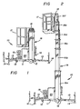
- Fig. 1 is a perspective view of a personnel lift with a telescopic mast, being an embodiment of the present invention, the mast shown in retracted position.
- Fig. 2 is a view as in Fig. 1 with the mast of Fig. 1 shown in an extended position.
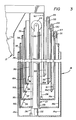
- Fig. 3 is a simplified cross-sectional view of the mast of Fig. 1, showing the various stages thereof and the apparatus for extending the mast.
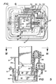
- Fig. 4 is a perspective view of one of the stages of the mast of Fig. 1.
- Fig. 5 is a vertical sectional view through portions of the three innermost stages of the mast of Fig. 1.
- Fig. 6 is a sectional view of the mast of Fig. 1.
- Referring now to the drawings, wherein is illustrated a preferred embodiment of the invention, Fig. 1 shows a
movable pedestal scaffold 10 having abase member 11 withwheels 12 at either end of the base member. As is conventional in these type units,outriggers 13, each with a vertically adjustableground engaging member 14, are attachable to thebase member 11 to provide an extended area of support for the unit. - At one end of the
base member 11, avertical mast 16 extends upwardly. As seen in Fig. 2, themast 16 comprises six telescopedmast sections 16a-f, theoutermost mast section 16a being mounted on thebase member 11. Awork cage 17 is mounted, bycantilever arm 18, to the upper end of theinnermost mast section 16f. As shown in the drawings, the work cage is spaced horizontally from theinnermost mast section 16f and extends downwardly from the upper end of themast section 16f and along one side of the mast. - A
ladder 19 on thebase member 11 enables a workman to climb up to the work cage when the cage is at its downwardly retracted position of Fig. 1. Also carried in thebase member 11, as generally indicated at 20, is apparatus for powering the elevation of thetelescopic mast 16 andwork cage 17. Typically,such apparatus 20 will include a hydraulic reservoir, a fluid pump and batteries for driving the pump. - Fig. 3 shows in simplified form the apparatus for vertical extension of the
sections 16b-f ofmast 16. A extensible fluid-operatedram 21 is vertically disposed centrally of themast 16, with itspiston member 22 secured to the lower end of theoutermost mast section 16a and with itscylinder member 12 secured to the lower end of the nextinnermost mast section 16b. Asprocket 24 is mounted on the upper end ofram 21 andchain 26 extends aroundsprocket 24 with one end of thechain 26 being connected to the lower end of theoutermost mast section 16a and with the other end of the chain being connected to the lower end ofmast section 16c. -
Additional sprockets mast sections Chain 31 extends from the upper end ofmast section 16b up oversprocket 27 and then down to the lower end ofmast section 16d. Likewise,chain 32 runs from the upper end ofmast section 16c upward oversprocket 28 and down to the lower end ofmast section 16e, whilechain 33 runs from the upper end ofmast section 16d up oversprocket 29 and down to the lower end of theinnermost mast section 16f. - In operation, vertical extension of
ram 21 will directly movemast section 16b upwardly frommast section 16a. This relative movement will incause chain 26 to pullmast section 16c upwardly relative tomast section 16b. In turn, this relative upward movement will causechain 31 to pullmast section 16d upwardly relative tomast section 16c. Likewise,chain 32 will pullmast section 16e upwardly relative tosection 16f, andchain 33 will pull theinnermost mast section 16f upwardly relative tosection 16e. - The lifting forces exerted by the chains on the mast sections are necessarily offset from the central axis of the mast. However, the offset forces are balanced to a considerable degree by the weight of the work cage and its occupant which are also offset from the central axis of the mast, but on the side of the mast opposite from the chain mechanism.
- The chains and sprockets described above are preferably doubled for the stages to equalize loading forces and to provide backup support in the event of a chain failure.
- Still with reference to Fig. 3, a plurality of fabric straps 36, 37, 38 and 39, made for example of nylon material, interconnect the mast sections on the side of the mast opposite to the chains described above, with each strap being secured to the upper end of a mast section and extending down to and around the lower end of the next innermost mast section and then being secured to the lower end of the then next innermost mast section. For example,
strap 36 is secured tomast section 16a, extends down around the lower end ofmast section 16b and is secured to the lower end ofmast section 16c. - In normal operation, the
mast 16 will retract downwardly with release of hydraulic fluid from theram 21 causingmast secsection 16b to move downwardly. The weight of the work cage wil cause the other mast sections to lower as thevarious sprockets - If however one of the mast sections should hang up during retraction then the straps 36-39 will serve to prevent retraction of lower mast sections. For example, suppose
mast section 16d were to hang up on some obstruction as it was moving downwardly. The lower end ofmast section 16d would then be "fixed" against further downward movement. Since the upper end of theoutermost mast section 16a is likewise fixed against vertical movement, straps 36 and 37 will supportmast sections Chains mast sections mast section 16d. - Thus, if any mast section is externally prevented from retracting downwardly, the straps and chains will prevent all of the other mast sections from retracting. The use of straps as disclosed is very advantageous since they are strong, flexible and can fit easily into the very restricted spaces between the mast sections. In case of such a hang up, the operator can then cause the mast to extend upwardly so that the obstruction can be removed. After that, retraction can take place in a normal manner.
- Figs. 4-6 illustrate the details of the sections of the
mast 12. Fig. 4 illustrates, in perspective,mast section 16c. As is shown,mast section 16c is made from two identical U-shaped channels 41 and 42 formed from thin-walled sheet aluminum. By way of example, personnel lifts have been built in accordance with the present invention with a 38 foot maximum platform height and using 5052 H32 sheet aluminum with a 0.060 inch wall thickness for the sheet aluminum mast sections. - Each U-shaped channel 41 and 42 is formed with substantially rounded
corners 43 and is deformed from the plane of thebase side 44 of the channel to provide astiffening rib 46 extending the full height of the channel. Thelegs 47 of the channel are also deformed from the planes of the legs to provide offsetend portions 48 parallel to the planes of the legs. The two channel sections 41 and 42 are placed with the offsetportions 48 adjacent to each other and are joined together byrivets 49 along the height of the mast section. The offset portions thus form a stiffening rib. - An
upper collar 51, preferably of cast aluminum, surrounds the upper end of the joined together sheet aluminum channels 41 and 42, thecollar 51 havingvertical flanges 52, to which the channels 41 and 42 are secured byrivets 53, and an outwardly projectinghorizontal flange 54. Thecollar 51 protects the upper edges of the sheet aluminum channels and maintains the rectangularity of the mast section. In addition, thecollar 51 supports sprocket 27 and provides a rigid member to whichchains 32 are secured. Likewise, thecollar 51 provides a rigid member for attachment ofstrap 38. - A similar, but inverted,
lower collar 56, also preferably of cast aluminum, extends around the inside of the joined together sheet aluminum channels and is secured thereto byrivets 57. This collar likewise protects the lower edges of the channels 41 and 42, maintains the rectangularity of the mast section, and provides a rigid member for attachment to the strap 36 (not shown in Fig. 4) secured thereto. For other mast sections, thelower collar 56 also provides a rigid member to whichchains - Each of the aluminum
sheet mast sections 16b-e has an upper andlower collar mast section 16c. Theoutermost mast section 16a has anupper collar 51 thereon, but nolower collar 56 is needed since the attachment of themast section 16a to theframe member 11 serves the purpose. - The preferred embodiment shown herein has an extruded aluminum tube as the
innermost mast section 16f. Because of the relatively small cross-sectional modulus of this innermost mast section, a thicker walled aluminum sheet would be necessary to withstand the high bending stresses. Further, the mast was designed so that the innermost mast section has a 4 x 4 inch size which is a standard, commercially available aluminum extrusion, with a 1/8 inch wall thickness. - For a six stage mast as illustrated herein, with a maximum platform height of 38 feet, the mast sections will range in height from about 7 feet for
mast section 16a to about 5½ feet for theinnermost mast section 16f. The cross-sectional area of the mast sections ranges from about 9 x 12 inches formast section 16a to 4 x 4 inches for themast section 16f. - With further reference to Fig. 4, the
mast section 16c has a set of four plastic slide blocks 61 mounted on the upper end of the mast section, with one of the slide blocks being mounted at each of the four inside corners of the mast section and secured thereto, as byscrews 62, the slide blocks being approximately 6 inches in height. Each slide block has anouter surface 63 of a shape complementary to the shape of the inside corner of the mast section to which it is secured and aninner surface 64 of a shape complementary to the shape of the outside corner of the nextinner mast section 16d adjacent thereto. Preferably, the slide blocks are made of UHMW (ultra high molecular weight) high density polyethylene. The slide blocks are placed at the corners of the mast sections where the mast sections are strongest and where the least amount of deformation will occur when the mast is under load. The rounded corners of the mast sections and the complementary shaped slide blocks serve to distribute the bearing pressure on the slide blocks and to distribute the force from the slide blocks onto a relatively large area of the thin-walled aluminum sheet mast sections. - In like manner,
mast section 16c has a set of fourslide blocks 66 mounted on the lower end of the mast section at the outside of each of the four corners. Slide blocks 66 each have aninner surface 67 of a shape complementary to the shape of the outside corner ofmast section 16c to which it is mounted and anouter surface 68 of a shape complementary to the shape of the inner corner of the next mast section adjacent thereto. Again, the shape of the slide blocks spreads the forces over a substantial area of the aluminum sheet instead of concentrating them at a sharp corner. - As may be seen from the foregoing, the present invention provides a mast that is relatively light in weight and relatively inexpensive to manufacture because it is largely made out of thin walled aluminum sheet rather than thicker and considerably more expensive aluminum extrusions. The relatively large rectangular cross-section of the mast section provides for a very efficient distribution of material while providing a very rigid mast which will resist bending forces from the cantilever mounted work cage and torsional forces impared by reaction forces by a workman working to his side while in the cage.
Claims (10)
- A pedestal scaffold having a base member (11) on which is mounted a mast (16) bearing a work platform (17) and comprising a plurality of telescopically nested mast sections (16a-f) which are substantially rectangular in cross-section, with means for extending the mast (16) upwardly by relative telescopic displacement of the mast sections, characterised in that at least some said mast sections (16b-e) are thin-walled tubes of sheet metal with rounded corners, each being provided with at least one stiffening rib (46) extending longitudinally in a side wall thereof, a set of inwardly projecting corner slide blocks (61) having respective inner surfaces (64) complementing the shape of and adapted to slide against outer corner surfaces of an inwardly adjacent mast section (16b-f) and a set of outwardly projecting corner slide blocks (66) having respective outer surfaces (68) complementing the shape of and adapted to slide against inner corner surfaces of an outwardly adjacent mast section (16a-d).
- A pedestal scaffold according to claim 1 wherein said inwardly projecting slide blocks (61) comprise four blocks mounted at the respective corners (43) at or near the upper end of the mast section (16b-e) and said outwardly projecting slide blocks (66) comprise four blocks mounted at the respective corners (43) at or near the lower end of the mast section (16b-e).
- A pedestal scaffold according to claim 1 or claim 2, wherein the walls of said at least some mast sections (16b-e) are of thin sheet aluminium.
- A pedestal scaffold according to any preceding claim wherein at least one of said mast sections (16a-f) comprises two substantially identical U-section longitudinal channels (41, 42), each channel (41, 42) having parallel offset end portions (48) on the longitudinal edges of the legs (47) of the U, the two channels (41, 42) opposing one another and joined along said offset end portions (48) such that said joined end portions (48) form stiffening ribs.
- A pedestal scaffold according to claim 4 wherein a base side (44) of each channel (41, 42) has a deformation out of its own plane providing a stiffening rib (46) extending along the channel (41, 42).
- A pedestal scaffold according to any preceding claims wherein the means for extending the mast (16) comprise an extensible ram (2) mounted to a first, lower mast section (16a) and to a second mast section (16b) inwardly adjacent the first mast section (16a) and operable to move said first and second sections apart, a sprocket (27, 28, 29) mounted at or near the upper end of at least one mast section (16c-e), and a chain (31, 32, 33) trained around the sprocket (27, 28, 29) and secured at or near the upper end of a mast section (16b-d) outwardly adjacent said at least one mast section (16c-e) and at or near the lower end of a mast section (16d-f) inwardly adjacent said at least one mast section (16c-e).
- A pedestal scaffold according to claim 6 wherein mast sections (16d-e) respectively have an upper collar (51) extending around and secured to the outside of the upper end of the mast section and a lower collar (56) extending around and secured to the inside of the lower end of the mast section, the sprocket (27, 28, 29) and chain (31, 32, 33) being respectively mounted on and secured to said collars (51, 56).
- A pedestal scaffold according to claim 6 or claim 7 wherein said sprockets (27, 28, 29) and chains (31, 32, 33) are disposed towards one side of the mast (16), there being a plurality of fabric strap members (36, 37, 38, 39) on the opposing side of the mast (16), each strap member (36, 37, 38, 39) being secured at or near the upper end of a mast section (16a-d) and extending down to and around the lower end of an inwardly adjacent mast section (16b-e) and secured at or near the lower end of the next inwardly adjacent mast section (16c-f).
- A pedestal scaffold according to any one of claims 6, 7 and 8 wherein the means for extending the mast (16) include a sprocket (24) mounted on an upper end of that part of the ram (2) mounted to the second mast section (16b) and a chain (26) trained around said sprocket (24), the chain (26) being secured at one end to the first, lower mast section (16a) and at the other end to a mast section (16c) inwardly adjacent the second mast section (16b).
- A pedestal scaffold according to any preceding claim wherein said slide blocks (61, 66) are of plastics material.
Applications Claiming Priority (2)
| Application Number | Priority Date | Filing Date | Title |
|---|---|---|---|
| US856050 | 1986-04-25 | ||
| US06/856,050 US4657112A (en) | 1986-04-25 | 1986-04-25 | Mast construction for pedestal scaffold |
Publications (3)
| Publication Number | Publication Date |
|---|---|
| EP0244060A2 EP0244060A2 (en) | 1987-11-04 |
| EP0244060A3 EP0244060A3 (en) | 1989-10-04 |
| EP0244060B1 true EP0244060B1 (en) | 1992-05-06 |
Family
ID=25322751
Family Applications (1)
| Application Number | Title | Priority Date | Filing Date |
|---|---|---|---|
| EP87301690A Expired EP0244060B1 (en) | 1986-04-25 | 1987-02-26 | Mast construction for pedestal scaffold |
Country Status (5)
| Country | Link |
|---|---|
| US (1) | US4657112A (en) |
| EP (1) | EP0244060B1 (en) |
| JP (1) | JPS62276162A (en) |
| AU (1) | AU586534B2 (en) |
| DE (1) | DE3778751D1 (en) |
Cited By (1)
| Publication number | Priority date | Publication date | Assignee | Title |
|---|---|---|---|---|
| US10060142B2 (en) | 2013-12-09 | 2018-08-28 | Haessler Inc. | Vertically elevating mobile work platform |
Families Citing this family (54)
| Publication number | Priority date | Publication date | Assignee | Title |
|---|---|---|---|---|
| US4783934A (en) * | 1986-11-21 | 1988-11-15 | United Production Services, Inc. | Free-standing assembly and method for making same |
| FR2632621B1 (en) * | 1988-06-10 | 1990-08-17 | Reel Sa | TELESCOPIC MAT FOR MAINTAINING AND MANEUVERING A NACELLE OR WORKING PLATFORM WHOSE MOVEMENTS ARE CONTROLLED BY A ROLLING BRIDGE |
| DE8903568U1 (en) * | 1989-03-17 | 1990-04-19 | Ramani, Zyber, 1000 Berlin | Work platform |
| US5111907A (en) * | 1990-02-20 | 1992-05-12 | Japanic Corporation | Lifting apparatus |
| IE68595B1 (en) * | 1990-09-10 | 1996-06-26 | Burt Will Comp | A drive |
| US5115606A (en) * | 1990-09-24 | 1992-05-26 | Ingersoll-Rand Company | Extension cable for telescopic tower |
| AU651616B2 (en) * | 1990-10-08 | 1994-07-28 | Kajima Corporation | Process for constructing frame and erection |
| US5209433A (en) * | 1991-01-28 | 1993-05-11 | Brown & Root U.S.A., Inc. | Mobile rocket service tower |
| JP2652592B2 (en) * | 1991-05-17 | 1997-09-10 | 日本スカイロボット株式会社 | Retractable mechanism such as telescopic columns |
| FR2717456B1 (en) * | 1994-03-16 | 1996-05-03 | Cimm | Staff lifting device. |
| US5803204A (en) * | 1995-10-23 | 1998-09-08 | Upright, Inc. | Personnel lift with clamshell cage assembly |
| EP1007466A1 (en) * | 1995-10-23 | 2000-06-14 | Up-Right, Inc. | Personnel lift with movable cage assembly |
| US5718087A (en) * | 1996-05-02 | 1998-02-17 | The Will-Burt Company | Telescoping mast assembly |
| US6174124B1 (en) * | 1996-10-04 | 2001-01-16 | Crown Equipment Corporation | Load trays for personnel carrying vehicles |
| CA2303253C (en) * | 1997-09-08 | 2005-12-20 | Crown Equipment Corporation | Personnel carrying vehicle |
| US6299336B1 (en) * | 1999-08-26 | 2001-10-09 | The Will-Burt Company | Low profile lift mounting arrangement for telescoping mast |
| US20080100707A1 (en) * | 2000-02-10 | 2008-05-01 | Cam Guard Systems, Inc. | Temporary surveillance system |
| US7465108B2 (en) * | 2000-02-10 | 2008-12-16 | Cam Guard Systems, Inc. | Temporary surveillance system |
| US6375370B1 (en) * | 2000-02-10 | 2002-04-23 | Cam Guard Systems, Inc. | Temporary surveillance system |
| US20030213766A1 (en) * | 2002-05-15 | 2003-11-20 | Komatsu Utility Europe S.P.A. | Telescopic arm |
| US20040123328A1 (en) * | 2002-12-20 | 2004-06-24 | Ecamsecure, Inc. | Mobile surveillance vehicle |
| ES2388338T3 (en) * | 2004-04-27 | 2012-10-11 | Jlg Industries, Inc. | Mast Lift Machine |
| US7966777B2 (en) * | 2004-06-25 | 2011-06-28 | Itt Manufacturing Enterprises, Inc. | Mechanical lift, fully nesting, telescoping mast |
| GB2434806A (en) * | 2006-02-03 | 2007-08-08 | Matthew Gladstone | Mast assembly |
| IL176246A0 (en) * | 2006-06-12 | 2006-10-05 | Amos Klein | Deployable watch tower |
| US8191322B2 (en) * | 2007-10-11 | 2012-06-05 | Frank Liestenfeltz | Payload mast |
| US8833523B2 (en) * | 2009-01-20 | 2014-09-16 | Clark Material Handling Company | Upright for a lift truck |
| US9878887B2 (en) | 2009-01-20 | 2018-01-30 | Clark Material Handling Company | Upright for a lift truck |
| WO2010131065A1 (en) * | 2009-05-11 | 2010-11-18 | Alfredo Medina Ramirez | Very tall, vertical extendable/retractable structure |
| RU2012116002A (en) * | 2009-09-21 | 2013-10-27 | Вольво Компакт Эквипмент Сас | SLIDING HANDLE FOR WITH EXTRUDED PART FOR REVERSE LEVER LEVER MECHANISM |
| US8418997B2 (en) * | 2009-10-23 | 2013-04-16 | Frank Bastone | Extendable support column |
| DE202010013830U1 (en) * | 2010-10-04 | 2011-07-06 | Lebro Verwertungs-GbR (vertretungsberechtigte Gesellschafter: Heinz Lehmann, 72175 Dornhan und Manfred Bronner, 72175 Dornhan), 72175 | Telescopic access platform |
| US8522511B2 (en) * | 2010-12-20 | 2013-09-03 | Raytheon Company | Methods and apparatus for mast system with enhanced load bearing |
| US8801354B2 (en) * | 2011-03-30 | 2014-08-12 | Terex South Dakota, Inc. | Wearpad arrangement |
| US8196233B1 (en) * | 2011-06-28 | 2012-06-12 | William L Daniels | Height adjustable toilet stand device |
| CN102556897B (en) * | 2011-12-14 | 2014-05-28 | 浙江中力机械有限公司 | Electric order picker |
| US9440830B2 (en) * | 2011-12-14 | 2016-09-13 | Big Lift, Llc | Personnel lift vehicle |
| US9758360B2 (en) * | 2013-10-09 | 2017-09-12 | Billy D. Stanford | Apparatus for providing safety netting on manlifts |
| USD730614S1 (en) | 2013-11-26 | 2015-05-26 | Big Lift, Llc. | Personnel lift vehicle |
| DE102014012493A1 (en) * | 2014-08-27 | 2016-03-03 | Schwing Gmbh | articulated mast |
| US9441761B2 (en) * | 2014-11-06 | 2016-09-13 | Raytheon Company | Telescoping mast cable management system |
| US20170137270A1 (en) * | 2015-11-16 | 2017-05-18 | Zhejiang Dingli Machinery Co., Ltd | Order picker for easy transfer of goods |
| US9701525B1 (en) * | 2016-08-04 | 2017-07-11 | Kan Cui | Elevating lift |
| US10611502B2 (en) | 2016-10-20 | 2020-04-07 | Roccor, Llc | Precision deployment devices, systems, and methods |
| US10723607B2 (en) * | 2017-03-24 | 2020-07-28 | Big Lift, Llc | Electric personnel lift device |
| US11724920B2 (en) | 2019-07-15 | 2023-08-15 | Roccor, Llc | Telescoping boom systems, devices, and methods |
| US11346381B2 (en) | 2019-09-20 | 2022-05-31 | Eagle Technology, Llc | Telescoping boom with cycling slit-tube deployer |
| US11535399B2 (en) * | 2020-06-09 | 2022-12-27 | The Boeing Company | Method and system for aircraft assembly and maintenance |
| US11183768B1 (en) | 2020-07-29 | 2021-11-23 | Eagle Technology, Llc | Dual boom deployable parabolic trough reflector |
| CN112249999A (en) * | 2020-11-06 | 2021-01-22 | 浙江鼎力机械股份有限公司 | Electric lifting type aerial work platform |
| US12371921B1 (en) * | 2022-10-14 | 2025-07-29 | Mark Dorn | Interchangeable pole support and device attachment system |
| USD1070220S1 (en) * | 2023-02-15 | 2025-04-08 | Oshkosh Corporation | Lift |
| US20240270547A1 (en) * | 2023-02-15 | 2024-08-15 | Oshkosh Corporation | Lift device |
| USD1070221S1 (en) * | 2023-07-21 | 2025-04-08 | Oshkosh Corporation | Lift |
Family Cites Families (24)
| Publication number | Priority date | Publication date | Assignee | Title |
|---|---|---|---|---|
| US2948363A (en) * | 1955-08-11 | 1960-08-09 | Grand Specialties Company | Telescoping elevators |
| US2966956A (en) * | 1960-02-26 | 1961-01-03 | Moore Corp Lee C | Extension tower for use with a fork lift truck |
| US3509965A (en) * | 1968-09-13 | 1970-05-05 | Maurice E Mitchell | Mobile overhead service unit |
| DE2009298A1 (en) * | 1969-10-30 | 1971-05-06 | Institut fur Fordertechnik Leipzig, χ 7034 Leipzig | Guide for telescopic booms |
| DD86072A1 (en) * | 1970-09-29 | 1971-11-20 | Klaus Haake | TELESKOPAUSLEGER, ESPECIALLY FOR AUTODREHRKRANE |
| US3796016A (en) * | 1971-11-26 | 1974-03-12 | Cascade Corp | Extensible material handling boom |
| US3789869A (en) * | 1972-01-24 | 1974-02-05 | Snorkel Fire Equipment Co | Fire-fighting apparatus and elongate cantilever boom assembly therefor |
| AU474466B2 (en) * | 1973-04-18 | 1974-10-24 | Schellenberg Heinz | Mobile lifter arrangement |
| US3931698A (en) * | 1974-11-20 | 1976-01-13 | The Warner & Swasey Company | Center guided crane boom |
| US4004695A (en) * | 1975-04-16 | 1977-01-25 | Fulton Industries, Inc. | Channel and plate telescopic crane boom |
| US4003168A (en) * | 1975-06-27 | 1977-01-18 | Walter Kidde & Company, Inc. | Crane boom of trapezoidal boom sections having reinforcing rings |
| FR2332227A1 (en) * | 1975-11-18 | 1977-06-17 | Laing & Son Ltd John | LIFTING GEAR |
| IT1074573B (en) * | 1976-12-29 | 1985-04-20 | Cella Spa | EQUIPMENT FOR LIFTING PLATFORMS FOR AIR MAINTENANCE |
| US4112649A (en) * | 1977-08-26 | 1978-09-12 | Harnischfeger Corporation | Boom section for telescopic crane boom |
| US4171598A (en) * | 1977-10-21 | 1979-10-23 | J. I. Case Company | Hollow boom construction |
| US4185426A (en) * | 1978-01-30 | 1980-01-29 | A-T-O Inc. | Extension/elevation intra-action device for aerial lift apparatus |
| US4168008A (en) * | 1978-02-23 | 1979-09-18 | Granryd Tod G | Telescopic crane boom having corrugated boom sections |
| US4258825A (en) * | 1978-05-18 | 1981-03-31 | Collins Pat L | Powered manlift cart |
| US4337601A (en) * | 1980-04-24 | 1982-07-06 | Harnischfeger Corporation | High-strength light-weight boom section for telescopic crane boom |
| DE3101017A1 (en) * | 1981-01-15 | 1982-08-05 | Fried. Krupp Gmbh, 4300 Essen | Plastic sliding bearing |
| US4459786A (en) * | 1981-10-27 | 1984-07-17 | Ro Corporation | Longitudinally bowed transversely polygonal boom for cranes and the like |
| US4397373A (en) * | 1982-01-25 | 1983-08-09 | Ream Michael D | Mobile pedestal scaffold |
| US4589520A (en) * | 1983-01-06 | 1986-05-20 | Tapfer David L | Platform service vehicle |
| US4592447A (en) * | 1985-09-27 | 1986-06-03 | Up-Right, Inc. | Movable pedestal scaffold |
-
1986
- 1986-04-25 US US06/856,050 patent/US4657112A/en not_active Expired - Lifetime
-
1987
- 1987-02-16 AU AU68850/87A patent/AU586534B2/en not_active Ceased
- 1987-02-26 EP EP87301690A patent/EP0244060B1/en not_active Expired
- 1987-02-26 DE DE8787301690T patent/DE3778751D1/en not_active Expired - Lifetime
- 1987-03-12 JP JP62055491A patent/JPS62276162A/en active Pending
Cited By (1)
| Publication number | Priority date | Publication date | Assignee | Title |
|---|---|---|---|---|
| US10060142B2 (en) | 2013-12-09 | 2018-08-28 | Haessler Inc. | Vertically elevating mobile work platform |
Also Published As
| Publication number | Publication date |
|---|---|
| EP0244060A3 (en) | 1989-10-04 |
| EP0244060A2 (en) | 1987-11-04 |
| AU586534B2 (en) | 1989-07-13 |
| US4657112A (en) | 1987-04-14 |
| DE3778751D1 (en) | 1992-06-11 |
| AU6885087A (en) | 1987-10-29 |
| JPS62276162A (en) | 1987-12-01 |
Similar Documents
| Publication | Publication Date | Title |
|---|---|---|
| EP0244060B1 (en) | Mast construction for pedestal scaffold | |
| US10023448B2 (en) | Lift truck with mast | |
| US5588500A (en) | Elevatable work facility | |
| US3876039A (en) | Mechanical lift truck | |
| US6003658A (en) | Telescoping rigid frame and scissor conveyor with suspension | |
| US4484663A (en) | Portable personnel platform lift | |
| US4102463A (en) | Transporter for slab casting tables | |
| US3752261A (en) | Multi-stage lift | |
| US4040774A (en) | Apparatus for constructing concrete walls | |
| US4848520A (en) | Telescopic mast assembly | |
| US3517771A (en) | Movable platform between metallurgical furnaces | |
| WO2024065963A1 (en) | Intelligent construction integrated platform and use method | |
| CA1196254A (en) | Telescopic differential column hydraulic cylinder | |
| US3366251A (en) | Climbing crane | |
| US3195751A (en) | Core lift for industrial trucks | |
| US3709393A (en) | Lift truck mast | |
| CN220645071U (en) | Portable height-adjustable operation platform frock | |
| US3235034A (en) | Triple lift truck with continuous lift chain | |
| CA1097266A (en) | Upright for lift truck | |
| CN216516769U (en) | Construction lifting platform for erecting steel pipe frame | |
| JPH08100517A (en) | Elevating workbench | |
| JP3583560B2 (en) | Elevated workbench with intermediate stage | |
| EP1369376B1 (en) | telescopic truck mast with balancing cylinder for the dead weight | |
| EP1007466A1 (en) | Personnel lift with movable cage assembly | |
| CN214403405U (en) | Auxiliary ladder for elevating fire truck |
Legal Events
| Date | Code | Title | Description |
|---|---|---|---|
| PUAI | Public reference made under article 153(3) epc to a published international application that has entered the european phase |
Free format text: ORIGINAL CODE: 0009012 |
|
| AK | Designated contracting states |
Kind code of ref document: A2 Designated state(s): DE FR GB SE |
|
| PUAL | Search report despatched |
Free format text: ORIGINAL CODE: 0009013 |
|
| AK | Designated contracting states |
Kind code of ref document: A3 Designated state(s): DE FR GB SE |
|
| 17P | Request for examination filed |
Effective date: 19900203 |
|
| 17Q | First examination report despatched |
Effective date: 19910228 |
|
| RAP3 | Party data changed (applicant data changed or rights of an application transferred) |
Owner name: UP-RIGHT, INC. |
|
| GRAA | (expected) grant |
Free format text: ORIGINAL CODE: 0009210 |
|
| AK | Designated contracting states |
Kind code of ref document: B1 Designated state(s): DE FR GB SE |
|
| REF | Corresponds to: |
Ref document number: 3778751 Country of ref document: DE Date of ref document: 19920611 |
|
| ET | Fr: translation filed | ||
| PGFP | Annual fee paid to national office [announced via postgrant information from national office to epo] |
Ref country code: GB Payment date: 19930216 Year of fee payment: 7 |
|
| PGFP | Annual fee paid to national office [announced via postgrant information from national office to epo] |
Ref country code: FR Payment date: 19930217 Year of fee payment: 7 |
|
| PGFP | Annual fee paid to national office [announced via postgrant information from national office to epo] |
Ref country code: SE Payment date: 19930219 Year of fee payment: 7 Ref country code: DE Payment date: 19930219 Year of fee payment: 7 |
|
| PLBE | No opposition filed within time limit |
Free format text: ORIGINAL CODE: 0009261 |
|
| STAA | Information on the status of an ep patent application or granted ep patent |
Free format text: STATUS: NO OPPOSITION FILED WITHIN TIME LIMIT |
|
| 26N | No opposition filed | ||
| PG25 | Lapsed in a contracting state [announced via postgrant information from national office to epo] |
Ref country code: GB Effective date: 19940226 |
|
| PG25 | Lapsed in a contracting state [announced via postgrant information from national office to epo] |
Ref country code: SE Effective date: 19940227 |
|
| GBPC | Gb: european patent ceased through non-payment of renewal fee |
Effective date: 19940226 |
|
| PG25 | Lapsed in a contracting state [announced via postgrant information from national office to epo] |
Ref country code: FR Effective date: 19941031 |
|
| PG25 | Lapsed in a contracting state [announced via postgrant information from national office to epo] |
Ref country code: DE Effective date: 19941101 |
|
| REG | Reference to a national code |
Ref country code: FR Ref legal event code: ST |
|
| EUG | Se: european patent has lapsed |
Ref document number: 87301690.1 Effective date: 19940910 |