EP0243825A2 - Mit Schleifkörnern überkrusteter Draht und Verfahren zu seiner Herstellung - Google Patents
Mit Schleifkörnern überkrusteter Draht und Verfahren zu seiner Herstellung Download PDFInfo
- Publication number
- EP0243825A2 EP0243825A2 EP87105714A EP87105714A EP0243825A2 EP 0243825 A2 EP0243825 A2 EP 0243825A2 EP 87105714 A EP87105714 A EP 87105714A EP 87105714 A EP87105714 A EP 87105714A EP 0243825 A2 EP0243825 A2 EP 0243825A2
- Authority
- EP
- European Patent Office
- Prior art keywords
- metallic
- wire
- abrasive grains
- pipe
- incrusted
- Prior art date
- Legal status (The legal status is an assumption and is not a legal conclusion. Google has not performed a legal analysis and makes no representation as to the accuracy of the status listed.)
- Granted
Links
Images

Classifications
-
- B—PERFORMING OPERATIONS; TRANSPORTING
- B22—CASTING; POWDER METALLURGY
- B22F—WORKING METALLIC POWDER; MANUFACTURE OF ARTICLES FROM METALLIC POWDER; MAKING METALLIC POWDER; APPARATUS OR DEVICES SPECIALLY ADAPTED FOR METALLIC POWDER
- B22F7/00—Manufacture of composite layers, workpieces, or articles, comprising metallic powder, by sintering the powder, with or without compacting wherein at least one part is obtained by sintering or compression
- B22F7/06—Manufacture of composite layers, workpieces, or articles, comprising metallic powder, by sintering the powder, with or without compacting wherein at least one part is obtained by sintering or compression of composite workpieces or articles from parts, e.g. to form tipped tools
- B22F7/08—Manufacture of composite layers, workpieces, or articles, comprising metallic powder, by sintering the powder, with or without compacting wherein at least one part is obtained by sintering or compression of composite workpieces or articles from parts, e.g. to form tipped tools with one or more parts not made from powder
-
- B—PERFORMING OPERATIONS; TRANSPORTING
- B22—CASTING; POWDER METALLURGY
- B22F—WORKING METALLIC POWDER; MANUFACTURE OF ARTICLES FROM METALLIC POWDER; MAKING METALLIC POWDER; APPARATUS OR DEVICES SPECIALLY ADAPTED FOR METALLIC POWDER
- B22F5/00—Manufacture of workpieces or articles from metallic powder characterised by the special shape of the product
- B22F5/12—Manufacture of workpieces or articles from metallic powder characterised by the special shape of the product of wires
-
- B—PERFORMING OPERATIONS; TRANSPORTING
- B23—MACHINE TOOLS; METAL-WORKING NOT OTHERWISE PROVIDED FOR
- B23D—PLANING; SLOTTING; SHEARING; BROACHING; SAWING; FILING; SCRAPING; LIKE OPERATIONS FOR WORKING METAL BY REMOVING MATERIAL, NOT OTHERWISE PROVIDED FOR
- B23D61/00—Tools for sawing machines or sawing devices; Clamping devices for these tools
- B23D61/18—Sawing tools of special type, e.g. wire saw strands, saw blades or saw wire equipped with diamonds or other abrasive particles in selected individual positions
- B23D61/185—Saw wires; Saw cables; Twisted saw strips
-
- B—PERFORMING OPERATIONS; TRANSPORTING
- B23—MACHINE TOOLS; METAL-WORKING NOT OTHERWISE PROVIDED FOR
- B23D—PLANING; SLOTTING; SHEARING; BROACHING; SAWING; FILING; SCRAPING; LIKE OPERATIONS FOR WORKING METAL BY REMOVING MATERIAL, NOT OTHERWISE PROVIDED FOR
- B23D65/00—Making tools for sawing machines or sawing devices for use in cutting any kind of material
-
- B—PERFORMING OPERATIONS; TRANSPORTING
- B24—GRINDING; POLISHING
- B24D—TOOLS FOR GRINDING, BUFFING OR SHARPENING
- B24D18/00—Manufacture of grinding tools or other grinding devices, e.g. wheels, not otherwise provided for
-
- B—PERFORMING OPERATIONS; TRANSPORTING
- B22—CASTING; POWDER METALLURGY
- B22F—WORKING METALLIC POWDER; MANUFACTURE OF ARTICLES FROM METALLIC POWDER; MAKING METALLIC POWDER; APPARATUS OR DEVICES SPECIALLY ADAPTED FOR METALLIC POWDER
- B22F5/00—Manufacture of workpieces or articles from metallic powder characterised by the special shape of the product
- B22F2005/001—Cutting tools, earth boring or grinding tool other than table ware
-
- Y—GENERAL TAGGING OF NEW TECHNOLOGICAL DEVELOPMENTS; GENERAL TAGGING OF CROSS-SECTIONAL TECHNOLOGIES SPANNING OVER SEVERAL SECTIONS OF THE IPC; TECHNICAL SUBJECTS COVERED BY FORMER USPC CROSS-REFERENCE ART COLLECTIONS [XRACs] AND DIGESTS
- Y10—TECHNICAL SUBJECTS COVERED BY FORMER USPC
- Y10T—TECHNICAL SUBJECTS COVERED BY FORMER US CLASSIFICATION
- Y10T29/00—Metal working
- Y10T29/49—Method of mechanical manufacture
- Y10T29/4998—Combined manufacture including applying or shaping of fluent material
- Y10T29/49988—Metal casting
- Y10T29/49989—Followed by cutting or removing material
-
- Y—GENERAL TAGGING OF NEW TECHNOLOGICAL DEVELOPMENTS; GENERAL TAGGING OF CROSS-SECTIONAL TECHNOLOGIES SPANNING OVER SEVERAL SECTIONS OF THE IPC; TECHNICAL SUBJECTS COVERED BY FORMER USPC CROSS-REFERENCE ART COLLECTIONS [XRACs] AND DIGESTS
- Y10—TECHNICAL SUBJECTS COVERED BY FORMER USPC
- Y10T—TECHNICAL SUBJECTS COVERED BY FORMER US CLASSIFICATION
- Y10T83/00—Cutting
- Y10T83/929—Tool or tool with support
- Y10T83/9292—Wire tool
Definitions
- the present invention relates to a metallic wire for cutting, grinding or chamfering processing of hard materials and the like and, in particular, to a metallic wire for cutting and grinding processing having abrasive grain powder arranged and retained uniformly and firmly in the surface layer and to a method for producing the metallic wire.
- a wire with high tensile strength that is, a so-called saw wire is used.
- processing such as cutting or the like is carried out under the condition that free abrasive grains are existing between the wire and a material to be processed and grinding actions are performed only by frictional force, so that a problem that the processing efficiency is bad is presented.
- electro-spark machining method for the cutting, there is a so-called electro-spark machining method in which a high voltage is applied between the wire and a material to be cut to cut the material by discharge between the both.
- the method has a problem that the material to be cut is limited only to electroconductive materials.
- double-structure wires such as wires coated with copper or aluminum are now in general used. If such an abrasive grain/steel structure wire as aimed by the invention is taken as a mere double-structure steel wire and a conventional manufacturing technology for the double-structure wires is applied to produce the abrasive grain/steel structure wire, a die for wire drawing is markedly attacked and abraded by the abrasive grains, for example, in a wire drawing process, so that it is impossible practically to apply the conventional wire drawing processing technology to the production of the above-mentioned abrasive grain/steel structure wire.
- an object of the invention is to provide an wire incrusted with effective abrasive grain powder more uniformly and firmly and having an improved cutting and grinding processing function.
- Another object of the invention is to provide a method for producing an abrasive grain incrusted wire having the surface layer made of more uniformly and firmly arranged effective abrasive grain powder to improve cutting and grinding processing function.
- the wire incrusted with abrasive grains according to the present invention is obtained by the following steps. First, a metallic rod made of a metallic material of the same kind with or different kind from a metallic pipe 1 made of a desired metallic material is inserted into the central part of the metallic pipe 1 with a gap S formed between the both to obtain a constructed metallic body A having desired dimensions, then the gap S is filled with a mixture D containing metallic powder 4 and abrasive grains 3 having Mohs hardness of 6 or more as the main component, and after that, end parts of the metallic body A are sealed hermetically.
- the residual metallic pipe 1 positioned at the outermost layer of the above-mentioned wire is removed by polishing, pickling, and the like and thus an abrasive grain incrusted wire having a mixed layer D ⁇ exposed on the surface of the central metallic rod 2 is obtained, the mixed layer D ⁇ having the above-mentioned abrasive grain 3 retained uniformly and firmly in the metallic layer 4 ⁇ consisting of sintered metallic powder.
- the first aspect and the second aspect of the invention are the thus obtained wire itself incrusted with abrasive grains and a method for producing the wire, respectively. It is a remarkable characteristic of the invention that abrasive grains mixed with the metallic powder are not limited to diamond powder and CBN (cubic boron nitride) powder but ceramics, superhard alloys, glass, and the like having Mohs hardness of 6 or more can be used as the abrasive grain, and, in particular, ceramics such as alumina (Al2O3), silicon nitride (Si3N4), and the like are also usable.
- the Mohs hardness herein is an empirical scale to determine the hardness of ores by comparison with ten kinds of ores providing standards.
- the standard ores in an order of the softest ore (having a scale of 1) to the hardest one (having a scale of 10) are talc, gypsum, calcite, fluorite, apatite, orthoclase, qualtz topaz, corundum, and diamond.
- Abrasive grains used in the invention have usually hardness larger than that of orthoclase standard having hardness of 6.
- Abrasive grains having hardness lower than that of orthoclase standard are not appropriate in respect of the performance of obtained wire incrusted with abrasive grains.
- the above-mentioned abrasive grains are usually mixed with metallic powder and the mixture in a powdered state is filled into a gap in the above-mentioned metallic body but it is effective to granulate the above- mentioned mixture and to fill the resulting granules into the gap for the purpose of preventing the metallic powder and the abrasive grains from separation or segregation caused by a difference in gravity between the both.
- a pipe-shaped metal B may be fitted tightly around the metallic rod 2 inserted into the central part of the metallic pipe 1 with a gap formed between the metal B and the pipe 1 or a thin metallic belt C may be wound around the above-mentioned rod to remove possibilities that, in a cold wire drawing process, the above-mentioned inserted metallic rod 2 is pierced with abrasive grains and it is notched in its central part.
- the outermost layer of the above-mentioned metallic body is a metallic pipe and a wire draw-working is brought into contact with only the metallic pipe during a wire drawing process, the wire drawing die is not brought into contact with the abrasive grain powder, so that the abrasive grain powder is firmly stuck to the wire.
- the wire of desired diameter has the outermost layer consisting of only the metallic pipe, if the metallic pipe layer is removed, the mixed layer containing abrasive grains is exposed on the outermost surface of the resulting wire. Accordingly, the wire incrusted with abrasive grains can be produced readily and cheaply.
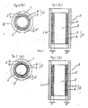
- Figs. 1(a) and 1(b) are a plan view and a side sectional view, each showing the structure of a metallic body A having a metallic rod 2 inserted into the central part of a metallic pipe 1 and having a gap between the metallic pipe and the metallic rod filled with a mixture principally comprising metallic powder and abrasive grains.
- A shows the metallic body, 1, the outermost metallic pipe, and 2, the metallic rod in the central part of metallic pipe.
- the metallic rod 2 is inserted into the central part of the metallic pipe 1 with a gap S formed between the two, and a mixture of abrasive grains 3 having a Mohs hardness of 6 or more with metallic powder 4 is filled into the gap S .
- carbon steel is used generally but stainless steel, a copper alloy, or the like may be used according to the use conditions, and materials of the metallic pipe 1 and the metallic rod 2 may be different from each other.
- the thickness of the metallic pipe 1, the diameter of the metallic rod 2, and the width of the gap between the both are each determined appropriately according to the diameter of a final wire for use, to the average grain size of abrasive grains 3 and to a mixing ratio of the abrasive grain 3 to the metallic powder 4.
- abrasive grain powder 3 having a Mohs hardness of 6 or more there are specifically, in additiion to diamond powder and CPN powder, ceramins such as alumina (Al2O3) and silicon nitride (Si3N4), hard metal powder, glass powder, and the like, and they are used in the form of a single compound or of a mixture of two or more compounds.
- Ni powder or Ni base alloy powder is generally used but, other than those, Cu powder, Cu base alloy powder, Co powder, Co base alloy powder, and the like which are bond metal powder used for manufacturing of general abrasive grain tools may be used.
- Both ends of gap S of the metallic body A after being filled with the mixed powder D are capped with an appropriate cover material and then welded to seal the metallic body A hermetically. After that, hot working such as extrusion or rolling and then a heat treatment such as annealing or patenting is applied and subsequently, cold working is applied to the metallic body A to produce a wire having a desired diameter.
- the diffusion of the metallic powder 4 filled in the gap between the metallic pipe 1 and the central metallic rod 2 into the metallic pipe 1 or into the metallic rod 2 during the hot working is undesirable, it is possible to prevent the diffusion phenomenon by plating the the inner surface of the metallic pipe 1 or the outer surface of the metallic rod 2 with copper or the like in advance to form a layer to prevent the diffusion.
- a pipe-shaped metal B may be fitted tightly around the metallic rod 2 inserted into the central part of metallic pipe 1 with a gap formed between the metal B and the pipe 1 or a thin metallic belt C may be wound around the rod 2. That is effective to remove possibilities that, in a cold working the above-mentioned inserted metallic rod 2 is pierced with abrasive grains and it is notched in its central part.
- a wire produced by use of the above-mentioned mixed powder having non-uniform composition and containing segregation shows a marked difference in the density of exposed abrasive grains at different locations on the wire surface, so that there are possibilities to provide an improper product.
- the mixed powder comprising diamond abrasive grains and Ni powder is granulated to prepare powder comprising spherical granules, which is filled into the gap between the above-mentioned metallic type and central metallic rod.
- a binder is added as an additive but if a binder such as an organic compound is used, joining between particles of powder is sometimes hindered by the above-mentioned binder when the above-mentioned metallic body is treated in after processes.
- the residual metallic pipe 1 as the outermost layer of the wire is removed by polishing, pickling and the like.
- Fig. 2 shows the thus obtained wire incrusted with abrasive grains having a mixed layer D ⁇ exposed on the surface of the drawn central metallic rod 2, the mixed layer D ⁇ having the abrasive grains retained uniformly and firmly in the metallic layer 4 ⁇ consisting of sintered metallic powder.
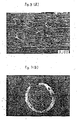
- Fig. 3(a) is a micrograph showing one example of the surface metallic structure of the thus obtained wire.
- JIS-SS 41 steel material was used for the peripheral metallic pipe 1 and JIS-SK 7 steel material for the central metallic rod 2.
- the outermost diameter was 70 mm ⁇
- the thickness of the peripheral metallic pipe was 5 mm
- the width of the gap S was 8 mm.
- abrasive grain diamond grains were used, and fine diamond powder having an average particle size of 150 ⁇ m was mixed with mixed powder prepared by mixing 0.5% by weight of carbon with pure nickel powder at a mixing ratio of 13% by volume of the diamond powder to prepare a mixture D . After the gap in the metallic body A was filled with the mixture D , both ends of the gap part were and sealed hermetically.
- Fig. 3(b) is a micrograph showing one example of metallic structure in the section of the wire.
- the thus obtained wire was dipped into a hydrochloric acid solution concentration of 35% for 15 minutes to dissolve and remove the carbon steel material (SS 41) of the metallic pipe which remained as the outermost layer of the wire and after that, it was neutralized with an alkali solution and washed with water.
- Fig. 3(a) is a micrograph showing one example of metallic structural state of the surface of the thus obtained wire incrusted with diamond abrasive grains, and it is realized that fine diamond grains are stuck to and embedded into the periphery of the wire uniformly and firmly.
- the material JIS-SS 41 steel material and JIS-SUS 304 stainless steel material were used for the peripheral metallic pipe 1 and for the central metallic rod 2, respectively.
- the outermost diameter was 70 mm, the thickness of the peripheral metallic pipe 5 mm and the width of the gap S in the metallic body A 8 mm.
- CBN grains were used, and CBN grains having an average particle size of 150 ⁇ m were mixed with pure nickel powder at a mixing ratio of 13% by volume of CBN grains to prepare a mixture D . After the gap part of the metallic body A was filled with the mixture D , both ends of the gap part were sealed hermetically.
- the metallic body A was heated at 1050°C for 2 hours and then extruded at an extrusion ratio of 15. Further, a heat treatment and cold working were repeated to produce a wire of 1.0 mm ⁇ .
- the tensile strength of the wire was 183 kg/mm2.
- the wire was dipped into a hydrochloric acid solution of concentration of 35% to dissolve and remove the outermost carbon steel material (SS 41) of the metallic body A which remained as the outermost layer of the wire and after that, it was neutralized with an alkali solution and washed with water.
- the thus obtained wire incrusted with abrasive grains was used for cutting and grinding processing of iron based materials and as a result, extremely good cutting and grinding processing could be performed, whereas, with the conventional diamond wires produced by a plating method, the surface diamond grains were abraded intensely owing to the action of the iron of the surface of the worked iron material and processing of the iron material with the wire was difficult.
- JIS-SS 41 steel material and JIS-SK 7 steel material were used for the outermost metallic pipe 1 and for the central metallic rod 2, respectively.
- the outermost diameter was 70 mm ⁇
- the thickness of the outermost metallic pipe 7 mm was 70 mm ⁇
- Diamond powder of average particle size of 30 ⁇ m was mixed with a mixture prepared by mixing 0.5% by weight of carbon with pure nickel powder at a mixing ratio of 15% by volume of diamond powder to produce mixed powder D . After the gap S of the metallic object A was filled with the mixed powder D , both ends of the gap S were sealed hermetically.
- the metallic object A was heated at 1050°C for 2 hours and then extruded at an extrusion ratio of 15. Further, a heat treatment and cold working were repeated to produce a wire of 0.26 mm ⁇ .
- the tensile strength of the wire was 179 kg/mm2.
- the wire was dipped into a hydrochloric acid solution of concentration of 35% for 5 minutes to dissolve and remove the outermost carbon steel material (SS 41) of the metallic object A which remained as the outermost layer of the wire and after that, it was neutralized with an alkali solution and washed with water.
- a carbon steel pipe JIS-STK 30
- a piano wire JIS-SWRS 72B
- the outermost diameter was 20 mm, the thickness of the metallic pipe 2 mm and the diameter of the metallic rod 13 mm.
- fine diamond powder having an average particle size of 30 ⁇ m was used as the abrasive grain.
- the diamond powder was mixed with Ni powder at a mixing ratio of 15% by volume of diamond powder to prepare a mixture and further, to the mixture, 0.5% by weight of camphor as a binder was added to prepare mixed powder. After that, the mixed powder was granulated by a wet spray method to prepare granules, which were then held in a nitrogen atmosphere at 300°C for 1 hour to sublime camphor. Thus, a mixture D comprising the granules was produced.
- both ends of the metallic body A were sealed hermetically.
- the metallic body A was not extruded but a heat treatment and cold working were repeated to produce a wire of 0.26 mm ⁇ .
- the tensile strength of the wire was 180 kg/mm2.
- the wire was used for cutting processing and as a result, good cutting performance comparable to that in Example 3 was obtained.
- a cargon steel material JIS-SS-41) and a carbon steel material (JIS-SK 7) were used for the peripheral metallic pipe 1 and for the central metallic rod 2, respectively.
- the outermost diameter was 70 mm, the thickness of the metallic pipe 5 mm, and the width of the gap S 6 mm.
- a pure nickel tube B having an inner diameter of 48 mm and a wall thickness of 2 mm was inserted into the gap S to fit it tightly around the metallic rod 2.
- Diamond powder having an average particle size of 120 m was mixed with a mixture prepared by mixing 0.5% by weight of carbon with pure nickel powder at a mixing ratio of 13% by volume of diamond powder to prepare mixed powder D.
- the metallic body A was heated at 1050°C for 2 hours, and then extruded at an extrusion ratio of 15. Further, a heat treatment and cold working were repeated to produce a wire of 1.0 mm ⁇ .
- the tensile strength of the wire was 168 kg/mm2.
- the structure of the wire was observed on a microphotograph and as a result, it was found that diamond particles were separated from the central metal rod by the pipe-shaped nickel metal and the central metal rod was not pierced with diamond particles and was not notched.
- the wire was dipped into a hydrochloric acid solution of concentration of 35% for 15 minutes to dissolve and remove the outermost metallic pipe of carbon steel (SS 41) of the metallic body A which remained as the outermost layer of the wire. After that, the resulting wire was neutralized with an aqueous alkali solution and washed with water.
- the thus obtained wire incrusted with diamond abrasive grains was a wire of long life which had the outer peripheral part stuck uniformly with diamond particles and the inside part not pierced with diamond particles into the center part and not notched.
- a carbon steel pipe JIS-STK 30
- a piano wire JIS-SWRS 72B
- the outermost diameter was 20 mm, the thickness of the metallic pipe 2 mm, and the diameter of the metallic rod 12 mm.
- a thin belt C of pure nickel of 0.1 mm thick was wound densely around the metallic rod 2 to form a nickel belt layer of thickness of 0.5 mm on the rod 2.
- mixed powder D prepared by mixing CBN abrasive grains 3 having an average grain size of 30 ⁇ m with pure nickel metal powder at a mixing ratio of 13% by volume of CBN abrasive grains 3, both ends of the gap S were capped and after that, were sealed hermetically.
- a heat treatment comprising heating to 950°C and subsequently being allowed to cool by air and cold working were applied to the metallic body A seven times repeatedly to produce a wire of diameter of 0.26 mm.
- the tensile strength of the wire was 171 kg/mm2.
- the wire was dipped into a hydrochloric acid solution of concentration of 35% for 5 minutes to dissolve and remove the outermost carbon steel (STK 30) material of the metallic body A which remained as the outermost layer of the wire. After that, the resulting wire was neutralized with an alkali solution and washed with water.
- the thus obtained wire incrusted with CBN abrasive grains was a wire of markedly long life which had no possibilities that the central metallic rod was pierced with CBN abrasive grains and was notched easily and the wire fractured easily, as compared with a wire incrusted with CNB abrasive grains of the same diameter produced by the conventional wire drawing method using none of a pipe-shaped metallic body and a thin metallic belt.
- a JIS-SS 41 steel material and a JIS-SUS 304 stainless steel material were used for the peripheral metallic pipe 1 and for the central metallic rod 2, respectively.
- the outermost diameter was 70 mm
- the thickness of the peripheral metallic pipe 5 mm was 70 mm
- the width of gap S 8 mm was 70 mm
- mixed powder D prepared by mixing alumina (A 2O3) powder 3 having an average particle size of 150 ⁇ m with pure Ni powder at a mixing ratio of 13% by volume of alumina
- the metallic body A was heated at 1050°C for 2 hours and then extruded at an extrusion ratio of 15. Further, a heat treatment and cold working were repeated to produce a wire of 1.0 mm ⁇ .
- the tensile strength of the wire was 183 kg/mm2.
- the wire was dipped into a hydrochloric acid solution of concentration of 35% to dissolve and remove the outermost carbon steel (SS 41) material of the metallic body A which remained as the outermost layer of the wire. After that, the resulting wire was neutralized with an alkali solution and washed with water.
- a carbon steel pipe JIS-STK 30
- a piano wire JIS-SWRS 72B
- the outermost diameter was 20 mm, the thickness of the metallic pipe 2 mm, and the diameter of the metallic rod 13 mm.
- mixed powder D prepared by mixing silicon nitride (Si3N4) powder 3 as abrasive particles having an average particle size of 30 ⁇ m with copper powder at a mixing ratio of 15% by volume of silicon nitride powder, both ends of the gap S of the metallic body A were sealed hermetically.
- a heat treatment comprising heating to 900°C and subsequently being allowed to cool in air and cold working were applied to the metallic body A seven times repeatedly to produce a wire of diameter of 0.26 mm.
- the tensile strength of the wire was 154 kg/mm2.
- the wire was dipped into a hydrochloric acid solution of concentration of 35% for 5 minutes to dissolve and remove the outermost carbon steel (STK 30) material of the metallic body A which remained as the outermost layer of the wire. After that, the resulting wire was neutralized with an alkali solution and washed with water.
- a metallic body formed easily into suitable dimensions and by suitable materials for use conditions is used, and after the gap within the metallic body is filled with mixed powder prepared by mixing metallic powder of desired components and mixed ratio with abrasive grains having Mohs hardness of 6 or more at a desired mixing ratio, both ends of the gap are welded and sealed hermetically.
- the outermost part of the metallic body is only a metal of metallic pipe, even if the conventional double structure wire producing technology is applied to the metallic body without any change, there are no possibilities that the abrasive grains directly attack a die for wire drawing, so that the metallic body can be subjected to wire drawing processing easily up to a desired wire diameter as in the production process for the conventional double structure steel wire.
- a metal remained on the surface of the wire can be removed readily by applying a usual polishing, pickling or the like.
- the above-mentioned abrasive grain powder in the mixed layer formed of sintered metallic powder in the mixed powder can be arranged and retained uniformly and firmly maintaining its mixing ratio at the time of filling unchanged.
- a wire incrusted with abrasive grains suitable for cutting and grinding processing can be produced readily, which can have an increased cutting speed and a markedly extended wire life and has very excellent cutting or chamfering processing performance as compared with the conventional diamond wire having diamond power only stuck to its surface by a plating method.
- the wire of the present invention has also markedly large retaining power for abrasive grains when the wire is bended as compared with the wire produced by the plating method.
- the wire incrusted with abrasive grains produced by the method of the invention has abrasive grains firmly embedded into the surface of wire, it, as a wire for precise cutting, is most suitable for cutting of a brittle material or of a material hard to be applied by a cutting method using a liquid such as water or an oil.
Landscapes
- Engineering & Computer Science (AREA)
- Mechanical Engineering (AREA)
- Manufacturing & Machinery (AREA)
- Chemical & Material Sciences (AREA)
- Composite Materials (AREA)
- Materials Engineering (AREA)
- Polishing Bodies And Polishing Tools (AREA)
Applications Claiming Priority (10)
| Application Number | Priority Date | Filing Date | Title |
|---|---|---|---|
| JP61089106A JPS6322217A (ja) | 1986-04-17 | 1986-04-17 | 立方晶窒化硼素インクラストワイヤおよびその製造方法 |
| JP8910586A JPS62260006A (ja) | 1986-04-17 | 1986-04-17 | ダイヤモンドインクラストワイヤおよびその製造方法 |
| JP89106/86 | 1986-04-17 | ||
| JP89105/86 | 1986-04-17 | ||
| JP14184486A JPS62297405A (ja) | 1986-06-17 | 1986-06-17 | ダイヤモンドインクラストワイヤの製造方法 |
| JP141845/86 | 1986-06-17 | ||
| JP61141845A JPS62297404A (ja) | 1986-06-17 | 1986-06-17 | 立方晶窒化硼素インクラストワイヤの製造方法 |
| JP141844/86 | 1986-06-17 | ||
| JP150108/86 | 1986-06-26 | ||
| JP15010886A JPS637304A (ja) | 1986-06-26 | 1986-06-26 | 砥粒インクラストワイヤ及びその製造方法 |
Publications (3)
| Publication Number | Publication Date |
|---|---|
| EP0243825A2 true EP0243825A2 (de) | 1987-11-04 |
| EP0243825A3 EP0243825A3 (en) | 1990-03-14 |
| EP0243825B1 EP0243825B1 (de) | 1994-01-05 |
Family
ID=27525400
Family Applications (1)
| Application Number | Title | Priority Date | Filing Date |
|---|---|---|---|
| EP19870105714 Expired - Lifetime EP0243825B1 (de) | 1986-04-17 | 1987-04-16 | Mit Schleifkörnern überkrusteter Draht und Verfahren zu seiner Herstellung |
Country Status (4)
| Country | Link |
|---|---|
| US (2) | US4866888A (de) |
| EP (1) | EP0243825B1 (de) |
| CA (1) | CA1305324C (de) |
| DE (1) | DE3788673T2 (de) |
Cited By (8)
| Publication number | Priority date | Publication date | Assignee | Title |
|---|---|---|---|---|
| EP0356923A1 (de) * | 1988-08-27 | 1990-03-07 | Ernst Winter & Sohn (Gmbh & Co.) | Säge |
| FR2747335A1 (fr) * | 1996-04-10 | 1997-10-17 | Schrall Philippe | Procede et machine pour decouper suivant une geometrie particuliere au moins une extremite d'un produit en mouvement |
| WO2010092151A1 (en) | 2009-02-13 | 2010-08-19 | Nv Bekaert Sa | Fixed abrasive sawing wire |
| WO2011144417A1 (en) | 2010-05-20 | 2011-11-24 | Nv Bekaert Sa | 3d porous material comprising machined side |
| CN103341829A (zh) * | 2013-07-17 | 2013-10-09 | 江西铜业股份有限公司 | 一种铜滑动轴承研磨棒及其制造工艺 |
| CN103624329A (zh) * | 2013-12-12 | 2014-03-12 | 唐山冶金锯片有限公司 | 可转位机卡式硬质合金齿圆锯片 |
| US9610642B2 (en) | 2012-04-02 | 2017-04-04 | Commissariat à l'énergie atomique et aux énergies alternatives | Process and apparatus for manufacturing an abrasive wire |
| CN107127347A (zh) * | 2017-05-18 | 2017-09-05 | 中国有色桂林矿产地质研究院有限公司 | 采用条坯组装烧结成型制作钻齿的方法 |
Families Citing this family (51)
| Publication number | Priority date | Publication date | Assignee | Title |
|---|---|---|---|---|
| ZA927268B (en) * | 1991-10-14 | 1993-03-25 | De Beers Ind Diamond | Ultra-hard abrasive particles. |
| TW307801B (de) * | 1992-03-19 | 1997-06-11 | Minnesota Mining & Mfg | |
| TW222668B (de) * | 1992-03-19 | 1994-04-21 | Minnesota Mining & Mfg | |
| US6352471B1 (en) | 1995-11-16 | 2002-03-05 | 3M Innovative Properties Company | Abrasive brush with filaments having plastic abrasive particles therein |
| US5795217A (en) * | 1995-11-22 | 1998-08-18 | International Business Machines Corporation | Stressed burnisher |
| CA2183829A1 (en) * | 1996-08-21 | 1998-02-22 | Chao Wang Tseng | Molded object having reinforcing member |
| US6194068B1 (en) * | 1996-11-08 | 2001-02-27 | Hitachi Cable Ltd. | Wire for wire saw apparatus |
| US9409280B2 (en) | 1997-04-04 | 2016-08-09 | Chien-Min Sung | Brazed diamond tools and methods for making the same |
| US9199357B2 (en) | 1997-04-04 | 2015-12-01 | Chien-Min Sung | Brazed diamond tools and methods for making the same |
| US7124753B2 (en) * | 1997-04-04 | 2006-10-24 | Chien-Min Sung | Brazed diamond tools and methods for making the same |
| US9238207B2 (en) | 1997-04-04 | 2016-01-19 | Chien-Min Sung | Brazed diamond tools and methods for making the same |
| US9868100B2 (en) | 1997-04-04 | 2018-01-16 | Chien-Min Sung | Brazed diamond tools and methods for making the same |
| US9221154B2 (en) | 1997-04-04 | 2015-12-29 | Chien-Min Sung | Diamond tools and methods for making the same |
| US9463552B2 (en) | 1997-04-04 | 2016-10-11 | Chien-Min Sung | Superbrasvie tools containing uniformly leveled superabrasive particles and associated methods |
| TW394723B (en) * | 1997-04-04 | 2000-06-21 | Sung Chien Min | Abrasive tools with patterned grit distribution and method of manufacture |
| US7368013B2 (en) * | 1997-04-04 | 2008-05-06 | Chien-Min Sung | Superabrasive particle synthesis with controlled placement of crystalline seeds |
| US7323049B2 (en) * | 1997-04-04 | 2008-01-29 | Chien-Min Sung | High pressure superabrasive particle synthesis |
| US6119319A (en) * | 1997-08-11 | 2000-09-19 | Redman Card Clothing Company, Inc. | Method and apparatus for surface finishing fabric with coated wires |
| US5956824A (en) * | 1997-08-11 | 1999-09-28 | Redman Card Clothing Co., Inc. | Equipment for use in baths disposed within molten metal plating baths |
| US6102024A (en) * | 1998-03-11 | 2000-08-15 | Norton Company | Brazed superabrasive wire saw and method therefor |
| JP2003071703A (ja) * | 2001-09-05 | 2003-03-12 | Seiko Instruments Inc | 多段式微小孔加工方法および装置 |
| US7466832B2 (en) * | 2002-07-31 | 2008-12-16 | Harman International Industries, Incorporated | Seatback audio controller |
| US6991289B2 (en) * | 2002-07-31 | 2006-01-31 | Harman International Industries, Incorporated | Seatback audio system |
| DE10252742A1 (de) * | 2002-11-13 | 2004-05-27 | Hilti Ag | Schärfmittel für Bohrkronen |
| US7089925B1 (en) | 2004-08-18 | 2006-08-15 | Kinik Company | Reciprocating wire saw for cutting hard materials |
| US8678878B2 (en) | 2009-09-29 | 2014-03-25 | Chien-Min Sung | System for evaluating and/or improving performance of a CMP pad dresser |
| US9724802B2 (en) | 2005-05-16 | 2017-08-08 | Chien-Min Sung | CMP pad dressers having leveled tips and associated methods |
| US8398466B2 (en) | 2006-11-16 | 2013-03-19 | Chien-Min Sung | CMP pad conditioners with mosaic abrasive segments and associated methods |
| US8393934B2 (en) | 2006-11-16 | 2013-03-12 | Chien-Min Sung | CMP pad dressers with hybridized abrasive surface and related methods |
| US9138862B2 (en) | 2011-05-23 | 2015-09-22 | Chien-Min Sung | CMP pad dresser having leveled tips and associated methods |
| EP1886753B1 (de) * | 2005-12-27 | 2009-04-15 | Japan Fine Steel Co., Ltd. | Fester schleifdraht |
| US8252263B2 (en) * | 2008-04-14 | 2012-08-28 | Chien-Min Sung | Device and method for growing diamond in a liquid phase |
| JP5639153B2 (ja) * | 2009-04-29 | 2014-12-10 | ナムローゼ・フェンノートシャップ・ベーカート・ソシエテ・アノニムN V Bekaert Societe Anonyme | 砥粒が部分的に金属ワイヤー中に埋め込まれ、かつ有機バインダーにより部分的に保持されたソーワイヤー |
| WO2010141206A2 (en) * | 2009-06-05 | 2010-12-09 | Applied Materials, Inc. | Method and apparatus for manufacturing an abrasive wire |
| CA2770508C (en) * | 2009-08-14 | 2014-10-28 | Saint-Gobain Abrasives, Inc. | Abrasive articles including abrasive particles bonded to an elongated body, and methods of forming thereof |
| KR101548147B1 (ko) | 2009-08-14 | 2015-08-28 | 생-고뱅 어브레이시브즈, 인코포레이티드 | 연신체에 연마입자가 결합된 연마제품 |
| CN103221180A (zh) * | 2010-09-21 | 2013-07-24 | 铼钻科技股份有限公司 | 具有基本平坦颗粒尖端的超研磨工具及其相关方法 |
| TWI466990B (zh) | 2010-12-30 | 2015-01-01 | 聖高拜磨料有限公司 | 磨料物品及形成方法 |
| CN103329253B (zh) | 2011-05-23 | 2016-03-30 | 宋健民 | 具有平坦化尖端的化学机械研磨垫修整器 |
| BR112014006126A2 (pt) | 2011-09-16 | 2017-04-11 | Saint Gobain Abrasifs Sa | artigo abrasivo e método de formação |
| EP2760638A4 (de) | 2011-09-29 | 2015-05-27 | Saint Gobain Abrasives Inc | Schleifartikel mit an einen langgestreckten trägerkörper mit einer sperrschicht gebundenen schleifpartikeln und verfahren zu ihrer herstellung |
| TW201404527A (zh) | 2012-06-29 | 2014-02-01 | 聖高拜磨料有限公司 | 研磨物品及形成方法 |
| TWI477343B (zh) | 2012-06-29 | 2015-03-21 | Saint Gobain Abrasives Inc | 研磨物品及形成方法 |
| TW201402274A (zh) | 2012-06-29 | 2014-01-16 | 聖高拜磨料有限公司 | 研磨物品及形成方法 |
| TW201441355A (zh) | 2013-04-19 | 2014-11-01 | 聖高拜磨料有限公司 | 研磨製品及其形成方法 |
| TWI664057B (zh) | 2015-06-29 | 2019-07-01 | 美商聖高拜磨料有限公司 | 研磨物品及形成方法 |
| CN106078374B (zh) * | 2016-08-12 | 2018-08-10 | 马鞍山市恒永利机械科技有限公司 | 一种工件内孔自动加工装置 |
| CN106041653B (zh) * | 2016-08-12 | 2018-08-17 | 马鞍山市恒永利机械科技有限公司 | 一种工件内孔自动加工方法 |
| CN106078378B (zh) * | 2016-08-12 | 2018-08-17 | 马鞍山市恒永利机械科技有限公司 | 一种全自动数控内圆磨 |
| CN106271917B (zh) * | 2016-08-12 | 2018-09-11 | 马鞍山市恒永利机械科技有限公司 | 一种利用全自动数控内圆磨进行内孔磨削的方法 |
| CN106426587B (zh) * | 2016-11-01 | 2018-08-07 | 天津恒瑜晶体材料股份有限公司 | 一种可调式非金属无机毛细管中心孔圆角研磨机 |
Family Cites Families (7)
| Publication number | Priority date | Publication date | Assignee | Title |
|---|---|---|---|---|
| US3168399A (en) * | 1960-05-11 | 1965-02-02 | Mitsubishi Atomic Power Ind | Method of producing circularly cylindrical members of material composed essentially of zirconium and/or niobium |
| US3708284A (en) * | 1970-01-26 | 1973-01-02 | Steel Corp | Method of converting metal powder into bar stock |
| GB1403192A (en) * | 1971-07-14 | 1975-08-28 | Int Research & Dev Co Ltd | Cutting tools |
| US3983357A (en) * | 1972-01-24 | 1976-09-28 | Remington Arms Company, Inc. | Apparatus for producing armored rod and wire saws |
| US4055700A (en) * | 1974-09-03 | 1977-10-25 | Lumalampan Ab | Thin composite wire saw with surface cutting crystals |
| JPS5244483A (en) * | 1975-10-06 | 1977-04-07 | Hitachi Ltd | Wire saw |
| JP3364944B2 (ja) * | 1992-02-28 | 2003-01-08 | ソニー株式会社 | 輝度信号増幅回路 |
-
1987
- 1987-04-16 EP EP19870105714 patent/EP0243825B1/de not_active Expired - Lifetime
- 1987-04-16 CA CA 534908 patent/CA1305324C/en not_active Expired - Lifetime
- 1987-04-16 DE DE87105714T patent/DE3788673T2/de not_active Expired - Fee Related
- 1987-04-17 US US07/039,253 patent/US4866888A/en not_active Expired - Fee Related
-
1989
- 1989-04-05 US US07/333,647 patent/US4964209A/en not_active Expired - Fee Related
Cited By (10)
| Publication number | Priority date | Publication date | Assignee | Title |
|---|---|---|---|---|
| EP0356923A1 (de) * | 1988-08-27 | 1990-03-07 | Ernst Winter & Sohn (Gmbh & Co.) | Säge |
| FR2747335A1 (fr) * | 1996-04-10 | 1997-10-17 | Schrall Philippe | Procede et machine pour decouper suivant une geometrie particuliere au moins une extremite d'un produit en mouvement |
| WO2010092151A1 (en) | 2009-02-13 | 2010-08-19 | Nv Bekaert Sa | Fixed abrasive sawing wire |
| WO2011144417A1 (en) | 2010-05-20 | 2011-11-24 | Nv Bekaert Sa | 3d porous material comprising machined side |
| US9610642B2 (en) | 2012-04-02 | 2017-04-04 | Commissariat à l'énergie atomique et aux énergies alternatives | Process and apparatus for manufacturing an abrasive wire |
| CN103341829A (zh) * | 2013-07-17 | 2013-10-09 | 江西铜业股份有限公司 | 一种铜滑动轴承研磨棒及其制造工艺 |
| CN103341829B (zh) * | 2013-07-17 | 2016-01-27 | 江西铜业股份有限公司 | 一种铜滑动轴承研磨棒及其制造工艺 |
| CN103624329A (zh) * | 2013-12-12 | 2014-03-12 | 唐山冶金锯片有限公司 | 可转位机卡式硬质合金齿圆锯片 |
| CN103624329B (zh) * | 2013-12-12 | 2016-06-01 | 唐山冶金锯片有限公司 | 可转位机卡式硬质合金齿圆锯片 |
| CN107127347A (zh) * | 2017-05-18 | 2017-09-05 | 中国有色桂林矿产地质研究院有限公司 | 采用条坯组装烧结成型制作钻齿的方法 |
Also Published As
| Publication number | Publication date |
|---|---|
| CA1305324C (en) | 1992-07-21 |
| US4964209A (en) | 1990-10-23 |
| DE3788673D1 (de) | 1994-02-17 |
| EP0243825B1 (de) | 1994-01-05 |
| US4866888A (en) | 1989-09-19 |
| EP0243825A3 (en) | 1990-03-14 |
| DE3788673T2 (de) | 1994-04-28 |
Similar Documents
| Publication | Publication Date | Title |
|---|---|---|
| EP0243825A2 (de) | Mit Schleifkörnern überkrusteter Draht und Verfahren zu seiner Herstellung | |
| US5035771A (en) | Process for treating diamond grains | |
| EP0403614B1 (de) | Mehrfach metallbeschichtete hochabrasive verschleisspartikel | |
| US4776861A (en) | Polycrystalline abrasive grit | |
| US5126207A (en) | Diamond having multiple coatings and methods for their manufacture | |
| CA2281546C (en) | Diamond sintered body having high strength and high wear resistance, andtool including the same | |
| EP0374424B1 (de) | Mit Silizium infiltrierte poröse polykristalline Diamantkörper | |
| HUT62831A (en) | Method for producing covered cubed leather-nitride abrasive grain, abrasive grain and grinding tool by using the same | |
| JPH0596401A (ja) | 気相合成ダイヤモンド被覆切削工具およびその製造法 | |
| JP2022068167A (ja) | 固有の形態を有する立方晶窒化ホウ素粒子 | |
| JP6687231B2 (ja) | 研磨工具及びその製造方法並びに研磨物の製造方法 | |
| KR100375649B1 (ko) | 연마 용구에 사용되는 제거가능한 결합제 | |
| EP0137711B1 (de) | Verfahren zur Herstellung von Schleifkörnern | |
| US7807220B2 (en) | Boron coated abrasives | |
| CN114787315B (zh) | 易破碎性金刚石磨粒及其制造方法 | |
| JP3456979B2 (ja) | シリコンウエハ外周部加工用ベベリングホイール | |
| RU2429195C1 (ru) | Способ получения шероховатости на поверхности алмазных зерен | |
| JPH03219079A (ja) | ダイヤモンド被覆炭化タングステン基超硬合金切削工具の製造法 | |
| JPH08150568A (ja) | 可撓性ダイヤモンド塗装研磨物体 | |
| JPH0377842B2 (de) | ||
| JP2001322067A (ja) | 金属炭化物被覆超砥粒の製造方法、金属炭化物被覆超砥粒および超砥粒工具 | |
| JPH0313283B2 (de) | ||
| JPH0521686B2 (de) | ||
| JPH04185667A (ja) | 被覆された超研摩材砥粒及びこれを含んでなる工具 | |
| JPS62161901A (ja) | ダイヤモンドワイヤの製造方法 |
Legal Events
| Date | Code | Title | Description |
|---|---|---|---|
| PUAI | Public reference made under article 153(3) epc to a published international application that has entered the european phase |
Free format text: ORIGINAL CODE: 0009012 |
|
| AK | Designated contracting states |
Kind code of ref document: A2 Designated state(s): BE DE FR GB |
|
| RIN1 | Information on inventor provided before grant (corrected) |
Inventor name: KAWAKITA, TAKAO OSAKA DIAMOND INDUSTRIAL CO., LTD Inventor name: HASHIMOTO, YOSHIHIRO Inventor name: MURAI, TERUYUKI |
|
| RIN1 | Information on inventor provided before grant (corrected) |
Inventor name: KAWAKITA, TAKAO OSAKA DIAMOND INDUSTRIAL CO., LTD Inventor name: HASHIMOTO, YOSHIHIRO Inventor name: MURAI, TERUYUKI |
|
| PUAL | Search report despatched |
Free format text: ORIGINAL CODE: 0009013 |
|
| AK | Designated contracting states |
Kind code of ref document: A3 Designated state(s): BE DE FR GB |
|
| 17P | Request for examination filed |
Effective date: 19900906 |
|
| 17Q | First examination report despatched |
Effective date: 19920122 |
|
| GRAA | (expected) grant |
Free format text: ORIGINAL CODE: 0009210 |
|
| AK | Designated contracting states |
Kind code of ref document: B1 Designated state(s): BE DE FR GB |
|
| REF | Corresponds to: |
Ref document number: 3788673 Country of ref document: DE Date of ref document: 19940217 |
|
| ET | Fr: translation filed | ||
| PLBE | No opposition filed within time limit |
Free format text: ORIGINAL CODE: 0009261 |
|
| STAA | Information on the status of an ep patent application or granted ep patent |
Free format text: STATUS: NO OPPOSITION FILED WITHIN TIME LIMIT |
|
| 26N | No opposition filed | ||
| PGFP | Annual fee paid to national office [announced via postgrant information from national office to epo] |
Ref country code: GB Payment date: 19950406 Year of fee payment: 9 |
|
| PGFP | Annual fee paid to national office [announced via postgrant information from national office to epo] |
Ref country code: DE Payment date: 19950410 Year of fee payment: 9 |
|
| PGFP | Annual fee paid to national office [announced via postgrant information from national office to epo] |
Ref country code: FR Payment date: 19950411 Year of fee payment: 9 |
|
| PGFP | Annual fee paid to national office [announced via postgrant information from national office to epo] |
Ref country code: BE Payment date: 19950602 Year of fee payment: 9 |
|
| PG25 | Lapsed in a contracting state [announced via postgrant information from national office to epo] |
Ref country code: GB Effective date: 19960416 |
|
| PG25 | Lapsed in a contracting state [announced via postgrant information from national office to epo] |
Ref country code: BE Effective date: 19960430 |
|
| BERE | Be: lapsed |
Owner name: SUMITOMO ELECTRIC INDUSTRIES LTD Effective date: 19960430 |
|
| GBPC | Gb: european patent ceased through non-payment of renewal fee |
Effective date: 19960416 |
|
| PG25 | Lapsed in a contracting state [announced via postgrant information from national office to epo] |
Ref country code: FR Effective date: 19961227 |
|
| PG25 | Lapsed in a contracting state [announced via postgrant information from national office to epo] |
Ref country code: DE Effective date: 19970101 |
|
| REG | Reference to a national code |
Ref country code: FR Ref legal event code: ST |