EP0243678A2 - Procédé et installation de purification de liquides par un filtre à plantes à écoulement réglé - Google Patents
Procédé et installation de purification de liquides par un filtre à plantes à écoulement réglé Download PDFInfo
- Publication number
- EP0243678A2 EP0243678A2 EP87104382A EP87104382A EP0243678A2 EP 0243678 A2 EP0243678 A2 EP 0243678A2 EP 87104382 A EP87104382 A EP 87104382A EP 87104382 A EP87104382 A EP 87104382A EP 0243678 A2 EP0243678 A2 EP 0243678A2
- Authority
- EP
- European Patent Office
- Prior art keywords
- filter bed
- drain
- planted filter
- flow
- bed
- Prior art date
- Legal status (The legal status is an assumption and is not a legal conclusion. Google has not performed a legal analysis and makes no representation as to the accuracy of the status listed.)
- Granted
Links
- 239000007788 liquid Substances 0.000 title claims abstract description 47
- 238000000034 method Methods 0.000 title claims description 40
- 238000009434 installation Methods 0.000 title claims 7
- 238000000746 purification Methods 0.000 title abstract description 4
- 230000008569 process Effects 0.000 title description 12
- 238000004140 cleaning Methods 0.000 claims description 10
- 230000008859 change Effects 0.000 claims description 8
- 230000004888 barrier function Effects 0.000 claims description 4
- 230000003698 anagen phase Effects 0.000 abstract 1
- 241000196324 Embryophyta Species 0.000 description 16
- 239000002689 soil Substances 0.000 description 15
- XLYOFNOQVPJJNP-UHFFFAOYSA-N water Substances O XLYOFNOQVPJJNP-UHFFFAOYSA-N 0.000 description 10
- 239000000126 substance Substances 0.000 description 9
- 230000035699 permeability Effects 0.000 description 7
- 238000011161 development Methods 0.000 description 6
- 230000000694 effects Effects 0.000 description 6
- 238000010276 construction Methods 0.000 description 5
- 230000003628 erosive effect Effects 0.000 description 5
- 239000002351 wastewater Substances 0.000 description 5
- 210000000056 organ Anatomy 0.000 description 4
- 244000273256 Phragmites communis Species 0.000 description 3
- 230000008901 benefit Effects 0.000 description 3
- 230000008595 infiltration Effects 0.000 description 3
- 238000001764 infiltration Methods 0.000 description 3
- 239000011159 matrix material Substances 0.000 description 3
- 239000004576 sand Substances 0.000 description 3
- 235000014676 Phragmites communis Nutrition 0.000 description 2
- 241000202758 Scirpus Species 0.000 description 2
- 238000006243 chemical reaction Methods 0.000 description 2
- 238000010790 dilution Methods 0.000 description 2
- 239000012895 dilution Substances 0.000 description 2
- 230000008030 elimination Effects 0.000 description 2
- 238000003379 elimination reaction Methods 0.000 description 2
- 230000002349 favourable effect Effects 0.000 description 2
- 239000003673 groundwater Substances 0.000 description 2
- 238000005325 percolation Methods 0.000 description 2
- 239000011148 porous material Substances 0.000 description 2
- 238000007789 sealing Methods 0.000 description 2
- 239000000758 substrate Substances 0.000 description 2
- 238000004065 wastewater treatment Methods 0.000 description 2
- 240000000491 Corchorus aestuans Species 0.000 description 1
- 235000011777 Corchorus aestuans Nutrition 0.000 description 1
- 235000010862 Corchorus capsularis Nutrition 0.000 description 1
- 229910019142 PO4 Inorganic materials 0.000 description 1
- 230000006978 adaptation Effects 0.000 description 1
- 230000001464 adherent effect Effects 0.000 description 1
- 230000002776 aggregation Effects 0.000 description 1
- 238000004220 aggregation Methods 0.000 description 1
- QVGXLLKOCUKJST-UHFFFAOYSA-N atomic oxygen Chemical compound [O] QVGXLLKOCUKJST-UHFFFAOYSA-N 0.000 description 1
- 230000000035 biogenic effect Effects 0.000 description 1
- 230000004071 biological effect Effects 0.000 description 1
- 230000031018 biological processes and functions Effects 0.000 description 1
- 230000015572 biosynthetic process Effects 0.000 description 1
- 230000000903 blocking effect Effects 0.000 description 1
- 229920002678 cellulose Polymers 0.000 description 1
- 239000001913 cellulose Substances 0.000 description 1
- 238000005352 clarification Methods 0.000 description 1
- 239000004927 clay Substances 0.000 description 1
- 238000007865 diluting Methods 0.000 description 1
- 238000006073 displacement reaction Methods 0.000 description 1
- 239000010840 domestic wastewater Substances 0.000 description 1
- 238000001035 drying Methods 0.000 description 1
- 239000010419 fine particle Substances 0.000 description 1
- 238000007689 inspection Methods 0.000 description 1
- 230000007774 longterm Effects 0.000 description 1
- 239000000463 material Substances 0.000 description 1
- 238000012067 mathematical method Methods 0.000 description 1
- 239000012528 membrane Substances 0.000 description 1
- 229910017464 nitrogen compound Inorganic materials 0.000 description 1
- 150000002830 nitrogen compounds Chemical class 0.000 description 1
- 235000019645 odor Nutrition 0.000 description 1
- 239000001301 oxygen Substances 0.000 description 1
- 229910052760 oxygen Inorganic materials 0.000 description 1
- 238000012856 packing Methods 0.000 description 1
- 230000000149 penetrating effect Effects 0.000 description 1
- 235000021317 phosphate Nutrition 0.000 description 1
- 150000003013 phosphoric acid derivatives Chemical class 0.000 description 1
- 238000012545 processing Methods 0.000 description 1
- 238000011160 research Methods 0.000 description 1
- 230000035943 smell Effects 0.000 description 1
- 239000007787 solid Substances 0.000 description 1
- 239000007858 starting material Substances 0.000 description 1
- 239000004753 textile Substances 0.000 description 1
Images

Classifications
-
- C—CHEMISTRY; METALLURGY
- C02—TREATMENT OF WATER, WASTE WATER, SEWAGE, OR SLUDGE
- C02F—TREATMENT OF WATER, WASTE WATER, SEWAGE, OR SLUDGE
- C02F3/00—Biological treatment of water, waste water, or sewage
- C02F3/32—Biological treatment of water, waste water, or sewage characterised by the animals or plants used, e.g. algae
- C02F3/327—Biological treatment of water, waste water, or sewage characterised by the animals or plants used, e.g. algae characterised by animals and plants
-
- Y—GENERAL TAGGING OF NEW TECHNOLOGICAL DEVELOPMENTS; GENERAL TAGGING OF CROSS-SECTIONAL TECHNOLOGIES SPANNING OVER SEVERAL SECTIONS OF THE IPC; TECHNICAL SUBJECTS COVERED BY FORMER USPC CROSS-REFERENCE ART COLLECTIONS [XRACs] AND DIGESTS
- Y02—TECHNOLOGIES OR APPLICATIONS FOR MITIGATION OR ADAPTATION AGAINST CLIMATE CHANGE
- Y02W—CLIMATE CHANGE MITIGATION TECHNOLOGIES RELATED TO WASTEWATER TREATMENT OR WASTE MANAGEMENT
- Y02W10/00—Technologies for wastewater treatment
- Y02W10/10—Biological treatment of water, waste water, or sewage
-
- Y—GENERAL TAGGING OF NEW TECHNOLOGICAL DEVELOPMENTS; GENERAL TAGGING OF CROSS-SECTIONAL TECHNOLOGIES SPANNING OVER SEVERAL SECTIONS OF THE IPC; TECHNICAL SUBJECTS COVERED BY FORMER USPC CROSS-REFERENCE ART COLLECTIONS [XRACs] AND DIGESTS
- Y02—TECHNOLOGIES OR APPLICATIONS FOR MITIGATION OR ADAPTATION AGAINST CLIMATE CHANGE
- Y02W—CLIMATE CHANGE MITIGATION TECHNOLOGIES RELATED TO WASTEWATER TREATMENT OR WASTE MANAGEMENT
- Y02W10/00—Technologies for wastewater treatment
- Y02W10/30—Wastewater or sewage treatment systems using renewable energies
- Y02W10/37—Wastewater or sewage treatment systems using renewable energies using solar energy
Definitions
- the invention relates to a method and a system for cleaning liquids, in which the liquid to be cleaned flows through a planted filter bed from an inlet to an outlet.
- Such planted filter beds are used to physi -, chemical and biological influences of percolating liquids, in particular waste water treatment.
- Planted filter beds of this type have become known in the past 10 to 20 years under the names "root chamber plants 1 ", "swamp bed clarification stages", “reed treatment plants” and others and are briefly described below in terms of structure and mode of operation.
- the liquid to be treated e.g. wastewater
- K f 10 -3 m / sec.
- high permeability remains maintain long-term values (k f ) even with permanent infiltration of liquids; This process can even counteract clogging of the soil pores by entrained solids.
- the effective bottom body of the filter bed forming the planted filter bed is suitably sealed against the subsurface in order to prevent the liquid to be cleaned from seeping away towards the groundwater and to ensure the horizontal percolation typical of this cleaning system through the planted filter bed.
- v k f (m / sec) ⁇ dh / ds according to DARCY are the flow velocity of the liquid along a hydraulic gradient dh / ds in a substrate with the permeability coefficient k f (m / sec) and 0 (m 2 ) the infiltration cross section, to transport the liquid to be cleaned with the bulk Q (m 3 / sec) in this way.
- the process-typical coarse pore structure in the root area of the marsh plants used which is decisive for liquid transport, is formed by restructuring and aggregate formation from the specified starting material, usually a heavier soil with significant clay and silt fractions.
- the object of the present invention is therefore to provide a method and a system of the type mentioned, in which, while avoiding the aforementioned problems, the cleaning effect achieved by the planted filter bed is always optimally adapted to the respective operating conditions.
- this object is achieved in that a in the planted filter bed. predetermined flow pattern is adjusted and adapted to the respective flow conditions of the planted filter bed.
- this object is achieved in that a flow control is provided, by means of which a predetermined, to the respective flow conditions of the planted Filter bed adapted flow pattern is adjustable.
- the flow control is carried out by adjusting means which change the flow cross-section on the outlet side, as a result of which the proportionate flow through the secondary flow path is adapted to the respective operating conditions of the planted filter bed becomes. In this way, the above-mentioned problems of surface runoff and surface erosion of the planted filter bed are avoided.
- ballast bed forming the secondary flow path
- the ballast bed on the side facing the planted filter bed is covered with a cover that can be dismantled by the planted filter bed. In this way, vertical erosion within the planted filter bed is effectively prevented during the pre-phase.
- the adjacent zones with increased, variable hydraulic gradients are formed by bypass flow paths from a predetermined number of transverse drainage pipes, each of which is laid on the bottom of the planted filter bed on the downstream side of the associated zone and on a common cross drainage drain are connected.
- the flow is controlled by adjusting means which change the flow cross-section at the individual transverse drainage pipes or the common transverse drainage drain, as a result of which the hydraulic gradient in each zone is adapted to the respective operating conditions of the planted filter bed. In this way, the total flow rate of the planted filter bed can be increased considerably even in the pre-phase.
- the hydraulic gradient between the height of the inlet level and the height of the outlet level is set by means of an outlet stroke.
- the at least one drain pipe of the drain is provided with an open end, for example by a flexible tube, tubular plug-in modules or a pivotable tubular arm, which can be adjusted to a selectable height above the drain pipe, whereby the flow rate is adapted to the feed rate of the liquid to be cleaned becomes.
- the exemplary embodiments of systems for cleaning liquids e.g. Wastewater represented by a planted filter bed.
- These exemplary embodiments contain a flow control for producing a specific flow pattern in each case in the planted filter bed.
- Each of these flow patterns enables an optimal adaptation of the flow or the flow rate of the planted filter bed to the respective operating conditions of the planted filter bed. These operating conditions can occur side by side or also in succession on the same planted filter bed, and it is therefore understood that individual or certain selected combinations or all of the flow controls described below and shown individually in the figures can be provided on a given planted filter bed.
- the excavated bed is filled with a suitable soil body, for example parabral soil (B horizon) or monolithic, loamy sand, which is planted with aquatic plants, for example the species phragmites, iris, scirpus and the like. Plants are generally used for this, which can supply oxygen to their root system and the adherent root space via their aerenchyma and thus build up a pattern of aerobic and anaerobic small areas in the hydromorphic soil matrix of the planted filter bed, which are responsible for the cleaning performance of the planted filter bed.
- a suitable soil body for example parabral soil (B horizon) or monolithic, loamy sand, which is planted with aquatic plants, for example the species phragmites, iris, scirpus and the like. Plants are generally used for this, which can supply oxygen to their root system and the adherent root space via their aerenchyma and thus build up a pattern of aerobic and anaerobic small areas in the hydromorphic soil matrix
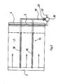
- the filter bed 2 planted with aquatic plants 1 can be seen, which is provided on one end face with an inlet 3 in the form of an inlet trench filled with ballast.
- a drain 4 which is designed as a drainage trench filled with gravel.
- a drain pipe 5, designed as a drainage pipe, runs in the drain 4 transversely to the filter bed 2 and receives the cleaned liquid emerging from the filter bed 2 and leads to a control shaft or to the receiving water.
- a predetermined number of Drain pipes are provided, which are designed in the manner of the drain pipes 40 shown in FIG. 4 a and drain the cleaned liquid from the planted filter bed 2 into the drain 4.
- the sole 7 and the side walls of the filter bed 2 are covered with a water-impermeable film 8.
- a ballast bed 9 of 15 to 20 cm in thickness is arranged between the filter bed 2 and the film 8 used for sealing against the groundwater body.
- a drainage lock 10 in the form of a floor block, for example up to 40 cm high, which the ballast bed 9 by a predetermined amount of e.g. exceeds up to 25 cm and over which the film 8 is guided, blocked.
- the drainage barrier 10 and the film 8 are traversed by one or more discharge pipes 11, only one of which can be seen in the sectional view of FIG.
- the discharge pipes 11 are connected to a common ballast bed drain 12, which leads to a drain shaft.
- the or each discharge pipe 11 is provided with preferably continuously adjustable setting means 13, e.g. Provide valves of any suitable type with which the flow cross-section of the associated discharge pipe 11 can be adjusted to values adapted to the respective operating conditions of the system.
- the setting means 13 can also be arranged on the common ballast bed drain 12.
- the ballast bed 9 has, particularly in the pre-phase of the planted filter bed 2, a considerably higher hydraulic conductivity than the planted filter bed 2 and runs parallel to the planted between the inlet 3 and the outlet 4 Filter bed 2.
- the ballast bed 9 and the discharge pipes 11 form a bypass flow path 15, and the setting means 13 adjust the flow through the bypass flow path 15.
- the secondary flow path 15 and the setting means 13 controlling this secondary flow path 15 thus represent a flow control, by means of which a flow pattern is formed in the system, which is determined by the proportionate flows through the planted filter bed 2 and the secondary flow path 15.
- the bypass flow path 15 or the ballast bed 9 is expediently covered against the effective, overlying soil body by a film 14 that can rot under the influence of the planted filter bed 2, for example a textile fleece, jute or cellulose webs, in order to prevent fine soil from penetrating during the construction work To prevent filter bed 2 in the ballast body of the ballast bed 9.
- a film 14 that can rot under the influence of the planted filter bed 2, for example a textile fleece, jute or cellulose webs, in order to prevent fine soil from penetrating during the construction work
- the plant roots and the fine soil will enter the ballast body of the ballast bed 9 immigrate and then put it in an increased activity state with respect to the cleaning target.
- ballast bed 9 in terms of the process objective, there is a further advantage that, in particular when using rounded ballast, e.g. Coarse gravel and with a packing layer of 20 cm, the underlying waterproof film 8 can be driven on with heavy construction equipment. This simplifies the structural measures when installing the effective floor structure of the system.
- rounded ballast e.g. Coarse gravel and with a packing layer of 20 cm
- the planted filter bed 2 can also be equipped with a longitudinal drainage in the direction of flow of the liquid to be treated. In principle, their arrangement and mode of operation are the same as in the ballast bed 9 explained above.
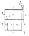
- Such a system is shown as a second exemplary embodiment in "top view in Fig. 2 and in it the same or analogous elements are provided with the same reference numerals as in Fig. 1.
- the planted filter bed 2 with the inlet 3 and the outlet 4 with a drain pipe 5 can be seen , which is connected to a control shaft 16, which leads to the receiving water via a further outlet 17.
- the secondary flow path 15 is formed here by a number predetermined by the flow cross section ⁇ , in the exemplary embodiment shown by 2 longitudinal drain pipes 18.
- the longitudinal drain pipes 18 run between the inlet 3 and the outlet 4 parallel to the planted filter bed 2 and preferably on the sole this filter bed 2 and are connected to a common longitudinal drainage outlet 19, which leads to the inspection shaft 16.
- the common longitudinal drainage outlet 19 is provided with preferably continuously adjustable setting means 20, for example a valve of a suitable type, by means of which the longitudinal drainage outlet can be adjusted in accordance with the respective operating conditions of the system.
- continuously adjustable setting means 20 for example a valve of a suitable type, by means of which the longitudinal drainage outlet can be adjusted in accordance with the respective operating conditions of the system.
- independent and individually adjustable setting means can also be provided on each individual longitudinal drain pipe 18.
- the longitudinal drainage pipes 18 are continued as closed pipes outside the planted filter bed 2.
- the bypass flow path 15 can not only effectively overcome the hydraulic bottlenecks during the development time of the planted filter bed system, but it can also reliably bring about the drying phases required during the development time.
- short-term dry phases are very advantageous. According to current knowledge, these should fall in the main feed times of the underground organs, ie in early and late winter, cf. the publication by L. Rodewald-Rudescu mentioned at the beginning.
- the flow control described here proves to be advantageous, if not essential.
- the flow control has controlled the amount Q of liquid passing through the plant through the flow through the bypass path 15.
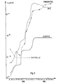
- the flow rate Q is the liquid percolating through the system per unit of time proportional to the permeability coefficient k f of the planted filter bed 2. As already mentioned at the beginning, this does not reach the climax value of around 10 -3 m / sec in the first years of operation, on which the dimensioning of the transport cross section ß is based, but develops during the pre-phase approximately in accordance with FIG. 5 from low initial values.
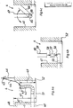
- FIG. 3 which, like the systems described above, contains a planted filter bed 2 with an inlet 3 and an outlet 4 with an outlet pipe 5, permits an increased flow rate Q by increasing the hydraulic gradient dh / ds.
- the planted filter bed 2 is provided with a secondary flow path 30, which consists of a transverse drainage, which divides the planted filter bed 2 into a predetermined number of adjacent zones or segments 31A, 31B ..., which are essentially transverse to the flow direction 32 through the planted filter bed 2 extend.
- the transverse drainage is formed by a predetermined number of transverse drainage pipes, which are preferably laid on the bottom of the planted filter bed 2 and on the downstream side of the associated zone.
- only one transverse drain pipe 33 is provided, which defines two zones or segments 31A and 31B.
- the transverse drain pipe 33 is connected to a transverse drainage outlet 34, which opens into a control shaft 35, into which the outlet pipe 5 also opens and which leads via a further outlet 36 to the receiving water.
- a plurality of transverse drain pipes 33 arranged in parallel and at a distance can also be provided, which are then connected together to the transverse drain outlet 34.
- the or each individual transverse drain pipe 33 is provided with an adjusting means 37, for example a valve of any suitable type, by means of which the flow cross section each individual transverse drain pipe 33 is independent and individually adjustable.
- the setting means 37 can also be provided on the common transverse drainage process.
- the transverse drainage pipes 33 thus form the secondary flow path 30, and the adjusting means 37 set the flow through the secondary flow path 30.
- the secondary flow path 30 and the setting means 37 controlling this secondary flow path 30 thus represent the flow control, by means of which a flow pattern is formed in the system, which is determined by zones or segments 31A, 31B ... of increased hydraulic gradient.
- the advantage of this embodiment is that a high degree of purification of the infiltrated liquid is achieved right from the start, because, in contrast to the exemplary embodiments described above, no partial quantities are short-circuited to the drain but the entire liquid is guided through the active bottom body of the planted filter bed 2. It is also advantageous that corresponding transverse drainage systems also after and after setting up and starting up the planted filter bed 2 even if the system needs to be renovated. Disadvantages compared to the exemplary embodiments described above are the small regulation range and the occurrence of superficial partial liquid streams which cannot be completely excluded and from which odors can emanate and which have an erosive effect.
- FIGS. 4a to 4c relate to a filter bed system of the type described above, of which only the sequence 4 is shown for simplification.
- This outlet 4 is provided with an outlet stroke control, by means of which the hydraulic gradient between the height of the inlet level at the inlet and the height of the outlet level at outlet 4 and thus over the entire flow path can be set as the flow pattern through the planted filter bed 2.
- This sequence stroke control can be provided as the only flow control, but is advantageously used in combination with at least one of the flow controls described in connection with the above exemplary embodiments.
- the area requirement is therein, D is a substance-specific reaction coefficient, Q the bed or flow rate per unit of time, c the feed concentration of a load substance from which the liquid is to be freed, and c T the desired drain concentration.
- the planted filter bed 2 for the dry weather case which makes up the majority of the operating conditions, is considerably oversized.
- this oversizing is by no means indifferent or even favorable for the elimination performance of the planted filter bed system, since the effectiveness of the planted filter bed 2 is largely linked to the permanent and complete hydromorphism of the effective soil matrix of the planted filter bed 2.
- Partially filled planted filter beds 2 are not fully effective, in particular for the removal of nitrogen compounds, phosphates and refractory organic substances.
- each drain pipe 40 emerging from the planted filter bed 2 open into a drain shaft 41 of drain 4.
- Each drain pipe 40 of which only one is visible in FIG. 4 a, has one end of a flexible pipe 42 on the output side connected, the free end 43 of which is arranged via a connecting link 44 like a chain on, for example, a hook-shaped fastening element 45 of a carrier 46 above the planted filter bed 2.
- a connecting link 44 like a chain on, for example, a hook-shaped fastening element 45 of a carrier 46 above the planted filter bed 2.
- the second embodiment according to FIG. 4b contains one or more drain pipes 55 emerging from the planted filter bed 2 with an open end 56 in a drain shaft 41 of drain 4, which leads via a further drain 52 to the receiving water.
- the height 49 of the drain mirror 50 is in this embodiment by the free end 58, 60 of tube shaped plug-in modules 57 and 59 of different lengths are determined, which can be plugged onto the open end 56 of the associated drain pipe 55 in a known manner and the length of which is selected in accordance with the respective operating conditions.
- the third embodiment according to FIG. 4c contains, in a drain shaft 41 of the drain 4, a drain pipe 65 in the longitudinal direction thereof, which is pivotally connected on the output side to a tubular arm 66 which is angled upwards by means of conventional pivot connection means 68.
- the tubular arm 66 has a free end 67.
- the height 49 of the drain mirror 50 is determined by the free end 67 of the tubular arm 66, which can be adjusted to selected swivel angles in accordance with the respective operating conditions.
- the height 49 of the drain mirror 50 can also be adjusted as a function of the hydraulic situation on the inlet 3 side, preferably using automatically controlled valve means.
- sequence stroke controls shown in Figures 4a to 4c are of great benefit in small systems with a small footprint and correspondingly short running distances, and are often indispensable, because with a controllable sequence stroke all length and width ratios of one are planned and constructed can realize such system.
- FIG. 5 shows in a semi-logarithmic representation the change in the permeability coefficient k f (m / s) with time in Para brown earth in the absence and in the presence of phragmites or iris and in a monolithic soil substrate made of loamy sand in the presence of scirpus.
Landscapes
- Life Sciences & Earth Sciences (AREA)
- Engineering & Computer Science (AREA)
- Biotechnology (AREA)
- Botany (AREA)
- Biodiversity & Conservation Biology (AREA)
- Microbiology (AREA)
- Hydrology & Water Resources (AREA)
- Environmental & Geological Engineering (AREA)
- Water Supply & Treatment (AREA)
- Chemical & Material Sciences (AREA)
- Organic Chemistry (AREA)
- Hydroponics (AREA)
- Farming Of Fish And Shellfish (AREA)
- Purification Treatments By Anaerobic Or Anaerobic And Aerobic Bacteria Or Animals (AREA)
- Filtration Of Liquid (AREA)
- Paper (AREA)
- Vehicle Body Suspensions (AREA)
- Flow Control (AREA)
- Developing Agents For Electrophotography (AREA)
Priority Applications (1)
| Application Number | Priority Date | Filing Date | Title |
|---|---|---|---|
| AT87104382T ATE97398T1 (de) | 1986-03-27 | 1987-03-25 | Verfahren und anlage zur fluessigkeitsreinigung mit durchflussgesteuertem bepflanzten filterbett. |
Applications Claiming Priority (2)
| Application Number | Priority Date | Filing Date | Title |
|---|---|---|---|
| GB8607653 | 1986-03-27 | ||
| GB8607653A GB8607653D0 (en) | 1986-03-27 | 1986-03-27 | Flow control system |
Publications (3)
| Publication Number | Publication Date |
|---|---|
| EP0243678A2 true EP0243678A2 (fr) | 1987-11-04 |
| EP0243678A3 EP0243678A3 (en) | 1989-08-30 |
| EP0243678B1 EP0243678B1 (fr) | 1993-11-18 |
Family
ID=10595346
Family Applications (1)
| Application Number | Title | Priority Date | Filing Date |
|---|---|---|---|
| EP19870104382 Expired - Lifetime EP0243678B1 (fr) | 1986-03-27 | 1987-03-25 | Procédé et installation de purification de liquides par un filtre à plantes à écoulement réglé |
Country Status (7)
| Country | Link |
|---|---|
| US (2) | US4855040A (fr) |
| EP (1) | EP0243678B1 (fr) |
| AT (1) | ATE97398T1 (fr) |
| AU (1) | AU594147B2 (fr) |
| DE (1) | DE3788153D1 (fr) |
| ES (1) | ES2046976T3 (fr) |
| GB (1) | GB8607653D0 (fr) |
Cited By (7)
| Publication number | Priority date | Publication date | Assignee | Title |
|---|---|---|---|---|
| DE3941211A1 (de) * | 1989-12-14 | 1991-06-20 | Fred Harf | Verfahren und vorrichtung zur behandlung von fluessigkeiten |
| AT396462B (de) * | 1991-10-28 | 1993-09-27 | Purator Umwelttechnik Gmbh | Verfahren und anlage zum versickern von abwasser |
| DE19630831A1 (de) * | 1996-07-31 | 1998-02-05 | Dernbach Heinrich Gmbh | Horizontal und vertikal druchströmte Pflanzenkläranlage |
| RU2149836C1 (ru) * | 1998-10-21 | 2000-05-27 | Российский научно-исследовательский институт комплексного использования и охраны водных ресурсов | Фитофильтр для очистки сточных вод |
| RU2219138C1 (ru) * | 2002-05-22 | 2003-12-20 | Хмыз Олег Николаевич | Способ очистки сточных вод с использованием элементов естественной экологической системы |
| DE19737690B4 (de) * | 1997-03-29 | 2006-03-02 | Böttcher, Joachim | Biologische Vertikal-Horizontal-Filteranlage zur Reinigung von Abwässern |
| RU2753349C1 (ru) * | 2020-08-18 | 2021-08-13 | Федеральное государственное бюджетное образовательное учреждение высшего образования "Кубанский государственный университет" (ФГБОУ ВО КубГУ") | Биоплато для очистки водоёмов с электронным блоком |
Families Citing this family (50)
| Publication number | Priority date | Publication date | Assignee | Title |
|---|---|---|---|---|
| JP2708454B2 (ja) * | 1988-03-25 | 1998-02-04 | 実男 稲垣 | 蒸発散式排水処理装置 |
| AU651828B2 (en) * | 1990-07-02 | 1994-08-04 | University Of New South Wales, The | Wastewater treatment system |
| US5947041A (en) * | 1991-02-04 | 1999-09-07 | Licht; Louis A. | Method for using tree crops as pollutant control |
| US6250237B1 (en) | 1991-02-04 | 2001-06-26 | Louis A. Licht | Method for using tree crops as pollutant control |
| US5106504A (en) * | 1991-02-12 | 1992-04-21 | Murray David P | Artificial open water structures |
| US5391020A (en) * | 1992-05-06 | 1995-02-21 | Sdvc, Inc. | Method for removing a substance from a medium |
| DE4237220A1 (de) * | 1992-11-04 | 1994-05-05 | Kickuth Reinhold | Verfahren und Anlagen zur Reinigung von Flüssigkeiten in horizontal durchströmten bepflanzten Filterbetten |
| GB9308085D0 (en) * | 1993-04-20 | 1993-06-02 | British Nuclear Fuels Plc | Liquid filtration system |
| US5393426A (en) * | 1993-06-04 | 1995-02-28 | Phytotech, Inc. | Method for removing soluble metals from an aqueous phase |
| IL109654A (en) * | 1993-06-04 | 1999-08-17 | Phytotech Inc | Phytoremediation of metals |
| US5364451A (en) * | 1993-06-04 | 1994-11-15 | Phytotech, Inc. | Phytoremediation of metals |
| GB2296916B (en) * | 1995-01-07 | 1998-11-04 | Reinhold Kickuth | Flow control for evening out waste water inflow in soil-based installations for waste water purification |
| US5809693A (en) * | 1995-04-13 | 1998-09-22 | Rutgers, The State University Of New Jersey | Microbial isolates promote phytoremediation |
| US5876484A (en) * | 1995-05-17 | 1999-03-02 | Phytotech, Inc. | Method for removing soluble metals from an aqueous phase |
| US5993649A (en) * | 1996-01-03 | 1999-11-30 | Debusk; Thomas A. | Sequential biological-chemical water treatment system |
| US5728300A (en) * | 1996-02-15 | 1998-03-17 | Phytotech, Inc. | Phytorecovery of metals using seedlings |
| US5917117A (en) * | 1996-03-21 | 1999-06-29 | Phytotech, Inc. | Inducing hyperaccumulation of metals in plant shoots |
| US5733453A (en) * | 1996-07-15 | 1998-03-31 | Azurea, Inc. | Wastewater treatment system and method |
| US6159371A (en) * | 1997-05-30 | 2000-12-12 | Albuquerque Public Schools District No. 12 | Constructed wetlands remediation system |
| US6200469B1 (en) | 1997-06-23 | 2001-03-13 | North American Wetland Engineering | System for removing pollutants from water |
| US6652743B2 (en) | 1997-06-23 | 2003-11-25 | North American Wetland Engineering, Inc. | System and method for removing pollutants from water |
| US5897777A (en) * | 1997-10-03 | 1999-04-27 | Zoeller Co. | Waste water treatment system |
| US6205708B1 (en) | 1997-11-17 | 2001-03-27 | Edward G. Gatliff | Treatment material pumping system |
| US6189262B1 (en) * | 1997-11-26 | 2001-02-20 | Edward G. Gatliff | Method of treating industrial waste water |
| US6277274B1 (en) | 1999-04-16 | 2001-08-21 | Larry Steven Coffman | Method and apparatus for treating stormwater runoff |
| GB2358858A (en) * | 1999-08-28 | 2001-08-08 | Oceans Environmental Engineeri | Portable wastewater treatment apparatus |
| US6830688B2 (en) * | 2001-11-14 | 2004-12-14 | Dharma Living Systems, Inc. | Integrated hydroponic and wetland wastewater treatment systems and associated methods |
| EP1451112A4 (fr) * | 2001-11-14 | 2006-06-21 | Dharma Living Systems Inc | Systemes de traitement des eaux usees integres, par hydroponie et sur couche fixe et procedes associes |
| US6863816B2 (en) * | 2002-06-17 | 2005-03-08 | Dharma Living Systems, Inc. | Tidal vertical flow wastewater treatment system and method |
| US6881338B2 (en) * | 2002-06-17 | 2005-04-19 | Dharma Living Systems, Inc. | Integrated tidal wastewater treatment system and method |
| US7029586B2 (en) * | 2003-02-28 | 2006-04-18 | Dharma Living Systems, Inc. | Integrated tidal wastewater treatment system and method |
| US7303078B2 (en) | 2003-05-30 | 2007-12-04 | Weatherford/Lamb, Inc. | Screen panel |
| US6896805B2 (en) * | 2003-10-20 | 2005-05-24 | Dharma Living Systems, Inc. | Tidal vertical flow wastewater treatment system and method |
| US20050097871A1 (en) * | 2003-11-12 | 2005-05-12 | Glassman Steven P. | Natural air exchange planter unit |
| US7510649B1 (en) * | 2004-01-09 | 2009-03-31 | Ronald Lavigne | Top loading vertical flow submerged bed wastewater treatment system |
| US7347940B2 (en) * | 2004-06-17 | 2008-03-25 | Worrell Water Technologies, Llc | Nitrogen removal system and method for wastewater treatment lagoons |
| US7101476B2 (en) * | 2004-07-15 | 2006-09-05 | Jung Yong Kim | Soil covered environmentally affirmative household sewage treatment system |
| CN1303017C (zh) * | 2004-08-09 | 2007-03-07 | 浙江大学 | 工厂化水产养殖废水综合处理方法及处理系统 |
| US20090288341A1 (en) * | 2006-07-25 | 2009-11-26 | Fountainhead, Llc | Buoyant plant habitat and process for its manufacture |
| US7941946B2 (en) * | 2007-09-27 | 2011-05-17 | Nike, Inc. | Article of footwear for sailing |
| RU2358916C1 (ru) * | 2007-11-20 | 2009-06-20 | Игорь Иосифович Конторович | Сооружение для очистки и регулирования качества дренажных вод |
| US7790035B2 (en) * | 2008-03-13 | 2010-09-07 | Premier Tech Technologies Ltee | Tertiary system and process for treating a liquid effluent from an onsite domestic secondary treatment unit |
| US8110105B2 (en) * | 2008-04-09 | 2012-02-07 | Contech Stormwater Solutions, Inc. | Stormwater filtration systems |
| US8287728B2 (en) * | 2009-02-10 | 2012-10-16 | Fountainhead L.L.C. | Elevated swale for treatment of contaminated stormwater |
| US9187342B2 (en) | 2010-06-14 | 2015-11-17 | Alcoa Inc. | Method for removing drugs from waste water using neutralized bauxite residue |
| US9085474B2 (en) | 2012-12-28 | 2015-07-21 | Lean Environment Inc. | Modular system for storm water and/or waste water treatment |
| CN105008289B (zh) | 2013-01-11 | 2017-06-06 | 奥科宁克有限公司 | 废水处理系统和方法 |
| US8889006B2 (en) | 2013-01-21 | 2014-11-18 | Leon A. Lassovsky | System for wastewater treatment using aquatic plants |
| US11306012B2 (en) | 2018-01-02 | 2022-04-19 | Reed Scientific Services Ltd. | Soil-based flow-through rhizosphere system for treatment of contaminated water and soil |
| US11148965B2 (en) | 2018-07-16 | 2021-10-19 | Yonathan RECHES | Process for the biological purification of nutrient-contaminated wastewater |
Family Cites Families (18)
| Publication number | Priority date | Publication date | Assignee | Title |
|---|---|---|---|---|
| US3770623A (en) * | 1971-06-15 | 1973-11-06 | Max Planck Gesellschaft | System for purification of polluted water |
| DE2210619A1 (de) * | 1972-03-06 | 1973-09-20 | Kickuth Reinhold | Biologische nachflockung zur abwasserbehandlung |
| AT315762B (de) * | 1972-10-24 | 1974-06-10 | Max Planck Gesellschaft | Verfahren zur Elimination von pathogenen Keimen aus Wasser |
| US3789986A (en) * | 1973-04-16 | 1974-02-05 | Oldham R Inc | Pivotable fluid diverter for recirculation system |
| DE2418979A1 (de) * | 1974-04-19 | 1975-10-30 | Max Planck Gesellschaft | Verfahren zur reinigung von farbstoffhaltigem abwasser |
| HU174397B (hu) * | 1977-08-04 | 1979-12-28 | Varosepitesi Tudomanyos | Sposob raffinirovki vod popadajuhhikh v priemnuju vodu i soderzhahhikh materialov prichinjajuhhikh ee eutrofizaciju, i apparat dlja sposoba |
| US4169050A (en) * | 1977-11-03 | 1979-09-25 | Solar Aquasystems, Inc. | Buoyant contact surfaces in waste treatment pond |
| US4388357A (en) * | 1979-01-23 | 1983-06-14 | True Temper Corporation | Sheet useful as a reservoir liner |
| DE2944421A1 (de) * | 1979-11-03 | 1981-05-14 | Reinhold Prof. Dr. 3436 Hessisch Lichtenau Kickuth | Verfahren zum aufbau definierter phosphatdepots aus abfallphosphaten |
| US4303350A (en) * | 1980-03-20 | 1981-12-01 | Dix Stephen P | Septic leaching system |
| DD202860A1 (de) * | 1981-07-15 | 1983-10-05 | Zbe Landbaugemeinschaft Niesky | Verfahren zum betreiben von algenteichen |
| US4415450A (en) * | 1981-12-28 | 1983-11-15 | The United States Of America As Represented By The Administrator Of The National Aeronautics And Space Administration | Method for treating wastewater using microorganisms and vascular aquatic plants |
| CH644570A5 (en) * | 1982-09-15 | 1984-08-15 | Willi Karl Felix | Phytobiological clarification plant with reversal of flow |
| DE3406004C2 (de) * | 1984-02-20 | 1986-09-25 | Gero Dr. 3300 Braunschweeig Benckiser | Verfahren und Anlage zur Abwasserreinigung mit Hilfe der Wurzelraumentsorgung |
| JPS6263729A (ja) * | 1985-09-12 | 1987-03-20 | 砂研株式会社 | 汚水の浄化方法 |
| US4678582A (en) * | 1986-01-24 | 1987-07-07 | Lavigne Ronald L | Treatment system for landfill leachate |
| DE3618029A1 (de) * | 1986-05-28 | 1987-12-03 | Kickuth Reinhold | Verfahren zur abwasserreinigung |
| US4824572A (en) * | 1988-04-01 | 1989-04-25 | Scott Richard E | Method and apparatus for treating household waste water |
-
1986
- 1986-03-27 GB GB8607653A patent/GB8607653D0/en active Pending
-
1987
- 1987-03-25 DE DE87104382T patent/DE3788153D1/de not_active Expired - Fee Related
- 1987-03-25 ES ES87104382T patent/ES2046976T3/es not_active Expired - Lifetime
- 1987-03-25 AT AT87104382T patent/ATE97398T1/de active
- 1987-03-25 EP EP19870104382 patent/EP0243678B1/fr not_active Expired - Lifetime
- 1987-03-26 US US07/031,339 patent/US4855040A/en not_active Expired - Fee Related
- 1987-04-28 AU AU72155/87A patent/AU594147B2/en not_active Ceased
-
1989
- 1989-03-28 US US07/329,769 patent/US4904386A/en not_active Expired - Fee Related
Cited By (8)
| Publication number | Priority date | Publication date | Assignee | Title |
|---|---|---|---|---|
| DE3941211A1 (de) * | 1989-12-14 | 1991-06-20 | Fred Harf | Verfahren und vorrichtung zur behandlung von fluessigkeiten |
| AT396462B (de) * | 1991-10-28 | 1993-09-27 | Purator Umwelttechnik Gmbh | Verfahren und anlage zum versickern von abwasser |
| DE19630831A1 (de) * | 1996-07-31 | 1998-02-05 | Dernbach Heinrich Gmbh | Horizontal und vertikal druchströmte Pflanzenkläranlage |
| DE19630831C2 (de) * | 1996-07-31 | 2002-04-25 | Heinrich Dernbach Inh Bernhard | Horizontal und vertikal druchströmte Pflanzenkläranlage |
| DE19737690B4 (de) * | 1997-03-29 | 2006-03-02 | Böttcher, Joachim | Biologische Vertikal-Horizontal-Filteranlage zur Reinigung von Abwässern |
| RU2149836C1 (ru) * | 1998-10-21 | 2000-05-27 | Российский научно-исследовательский институт комплексного использования и охраны водных ресурсов | Фитофильтр для очистки сточных вод |
| RU2219138C1 (ru) * | 2002-05-22 | 2003-12-20 | Хмыз Олег Николаевич | Способ очистки сточных вод с использованием элементов естественной экологической системы |
| RU2753349C1 (ru) * | 2020-08-18 | 2021-08-13 | Федеральное государственное бюджетное образовательное учреждение высшего образования "Кубанский государственный университет" (ФГБОУ ВО КубГУ") | Биоплато для очистки водоёмов с электронным блоком |
Also Published As
| Publication number | Publication date |
|---|---|
| US4904386A (en) | 1990-02-27 |
| AU594147B2 (en) | 1990-03-01 |
| EP0243678A3 (en) | 1989-08-30 |
| ES2046976T3 (es) | 1994-02-16 |
| GB8607653D0 (en) | 1986-04-30 |
| US4855040A (en) | 1989-08-08 |
| ATE97398T1 (de) | 1993-12-15 |
| DE3788153D1 (de) | 1993-12-23 |
| EP0243678B1 (fr) | 1993-11-18 |
| AU7215587A (en) | 1988-11-03 |
Similar Documents
| Publication | Publication Date | Title |
|---|---|---|
| EP0243678B1 (fr) | Procédé et installation de purification de liquides par un filtre à plantes à écoulement réglé | |
| DE69428211T2 (de) | Unterirdisches drainagesystem | |
| DE2161310C3 (de) | Verfahren zum wenigstens teilweisen Abscheiden von in einer Flüssigkeit verteilten Feststoffteilchen mit Hilfe der Schwerkraft und Vorrichtung zur Durchführung des Verfahrens | |
| DE4237220A1 (de) | Verfahren und Anlagen zur Reinigung von Flüssigkeiten in horizontal durchströmten bepflanzten Filterbetten | |
| DE2727956A1 (de) | Schichtenaufbau fuer unterirdisch be- und entwaesserbare sport- und spielplaetze sowie vegetationsflaechen aller art | |
| DE3423226C2 (fr) | ||
| AT393116B (de) | Verfahren und anlage zum reinigen von abwasser | |
| DE3712419C2 (fr) | ||
| EP0892764B1 (fr) | Transformation de boues de curage en humus | |
| DE10010109A1 (de) | Kompakt-Bodenfilter-Reaktor | |
| EP1001107A1 (fr) | Système d'écoulement de toit | |
| DE2253906A1 (de) | Gartenanlage | |
| DE69921623T2 (de) | Verfahren zur Behandlung von Entwässerungsflüssigkeit | |
| DE2163283B2 (de) | Verfahren und Anlage zur Reinigung von Abwasser | |
| DE69503080T2 (de) | Filter zur Reinigung von Wasser | |
| DE69308886T3 (de) | Entfernung von verunreinigungen | |
| WO1995000264A1 (fr) | Procede de traitement de sols contamines et dispositif de mise en ×uvre dudit procede | |
| CH671571A5 (en) | Filter bed for waste water treatment - planted with nitrophilic aquatic plants for denitrification and iron scrap for phosphate pptn. | |
| EP0924357A2 (fr) | Structure de déversement pour eaux pluviales | |
| DE102021005970A1 (de) | Mehrstufige Behandlungsanlage für Regenwasser | |
| DE29622246U1 (de) | Abwasserreinigungsanlage mit einem Wurzelraumklärbereich | |
| DE102021122297B4 (de) | Wassertank | |
| DE19859415A1 (de) | Regenwasserentlastungsanlage | |
| AT396228B (de) | Abwasserklaeranlage | |
| DE102021111854B4 (de) | Wasserabflussbremssystem aus Beton |
Legal Events
| Date | Code | Title | Description |
|---|---|---|---|
| PUAI | Public reference made under article 153(3) epc to a published international application that has entered the european phase |
Free format text: ORIGINAL CODE: 0009012 |
|
| AK | Designated contracting states |
Kind code of ref document: A2 Designated state(s): AT BE CH DE ES FR GB GR IT LI LU NL SE |
|
| PUAL | Search report despatched |
Free format text: ORIGINAL CODE: 0009013 |
|
| AK | Designated contracting states |
Kind code of ref document: A3 Designated state(s): AT BE CH DE ES FR GB GR IT LI LU NL SE |
|
| 17P | Request for examination filed |
Effective date: 19900203 |
|
| RBV | Designated contracting states (corrected) |
Designated state(s): AT DE ES FR GB IT |
|
| 17Q | First examination report despatched |
Effective date: 19920127 |
|
| GRAA | (expected) grant |
Free format text: ORIGINAL CODE: 0009210 |
|
| AK | Designated contracting states |
Kind code of ref document: B1 Designated state(s): AT DE ES FR GB IT |
|
| REF | Corresponds to: |
Ref document number: 97398 Country of ref document: AT Date of ref document: 19931215 Kind code of ref document: T |
|
| REF | Corresponds to: |
Ref document number: 3788153 Country of ref document: DE Date of ref document: 19931223 |
|
| REG | Reference to a national code |
Ref country code: ES Ref legal event code: FG2A Ref document number: 2046976 Country of ref document: ES Kind code of ref document: T3 |
|
| ITF | It: translation for a ep patent filed | ||
| GBT | Gb: translation of ep patent filed (gb section 77(6)(a)/1977) |
Effective date: 19940211 |
|
| ET | Fr: translation filed | ||
| PLBE | No opposition filed within time limit |
Free format text: ORIGINAL CODE: 0009261 |
|
| STAA | Information on the status of an ep patent application or granted ep patent |
Free format text: STATUS: NO OPPOSITION FILED WITHIN TIME LIMIT |
|
| 26N | No opposition filed | ||
| PGFP | Annual fee paid to national office [announced via postgrant information from national office to epo] |
Ref country code: FR Payment date: 19960215 Year of fee payment: 10 |
|
| PGFP | Annual fee paid to national office [announced via postgrant information from national office to epo] |
Ref country code: AT Payment date: 19960314 Year of fee payment: 10 |
|
| PG25 | Lapsed in a contracting state [announced via postgrant information from national office to epo] |
Ref country code: AT Effective date: 19970325 |
|
| PG25 | Lapsed in a contracting state [announced via postgrant information from national office to epo] |
Ref country code: FR Free format text: LAPSE BECAUSE OF NON-PAYMENT OF DUE FEES Effective date: 19971128 |
|
| REG | Reference to a national code |
Ref country code: FR Ref legal event code: ST |
|
| PGFP | Annual fee paid to national office [announced via postgrant information from national office to epo] |
Ref country code: GB Payment date: 19980312 Year of fee payment: 12 |
|
| PGFP | Annual fee paid to national office [announced via postgrant information from national office to epo] |
Ref country code: DE Payment date: 19980526 Year of fee payment: 12 |
|
| PG25 | Lapsed in a contracting state [announced via postgrant information from national office to epo] |
Ref country code: GB Free format text: LAPSE BECAUSE OF NON-PAYMENT OF DUE FEES Effective date: 19990325 |
|
| GBPC | Gb: european patent ceased through non-payment of renewal fee |
Effective date: 19990325 |
|
| PG25 | Lapsed in a contracting state [announced via postgrant information from national office to epo] |
Ref country code: DE Free format text: LAPSE BECAUSE OF NON-PAYMENT OF DUE FEES Effective date: 20000101 |
|
| PGFP | Annual fee paid to national office [announced via postgrant information from national office to epo] |
Ref country code: ES Payment date: 20000316 Year of fee payment: 14 |
|
| PG25 | Lapsed in a contracting state [announced via postgrant information from national office to epo] |
Ref country code: ES Free format text: LAPSE BECAUSE OF NON-PAYMENT OF DUE FEES Effective date: 20010326 |
|
| REG | Reference to a national code |
Ref country code: ES Ref legal event code: FD2A Effective date: 20030203 |
|
| PG25 | Lapsed in a contracting state [announced via postgrant information from national office to epo] |
Ref country code: IT Free format text: LAPSE BECAUSE OF NON-PAYMENT OF DUE FEES;WARNING: LAPSES OF ITALIAN PATENTS WITH EFFECTIVE DATE BEFORE 2007 MAY HAVE OCCURRED AT ANY TIME BEFORE 2007. THE CORRECT EFFECTIVE DATE MAY BE DIFFERENT FROM THE ONE RECORDED. Effective date: 20050325 |