EP0243578B1 - Procédé pour la fabrication d'une bague de palier à roulement comprenant un joint éclaté continu en au moins un endroit de sa périphérie - Google Patents
Procédé pour la fabrication d'une bague de palier à roulement comprenant un joint éclaté continu en au moins un endroit de sa périphérie Download PDFInfo
- Publication number
- EP0243578B1 EP0243578B1 EP87100776A EP87100776A EP0243578B1 EP 0243578 B1 EP0243578 B1 EP 0243578B1 EP 87100776 A EP87100776 A EP 87100776A EP 87100776 A EP87100776 A EP 87100776A EP 0243578 B1 EP0243578 B1 EP 0243578B1
- Authority
- EP
- European Patent Office
- Prior art keywords
- bearing ring
- rolling bearing
- manufacturing
- subjected
- seating face
- Prior art date
- Legal status (The legal status is an assumption and is not a legal conclusion. Google has not performed a legal analysis and makes no representation as to the accuracy of the status listed.)
- Expired - Lifetime
Links
- 238000005096 rolling process Methods 0.000 title claims description 13
- 238000004519 manufacturing process Methods 0.000 title claims description 5
- 230000005855 radiation Effects 0.000 claims description 15
- 238000000034 method Methods 0.000 claims description 8
- 238000010894 electron beam technology Methods 0.000 claims description 2
- 239000002360 explosive Substances 0.000 description 12
- 238000005422 blasting Methods 0.000 description 11
- 244000248349 Citrus limon Species 0.000 description 2
- 235000005979 Citrus limon Nutrition 0.000 description 2
- 239000000463 material Substances 0.000 description 2
- 230000015572 biosynthetic process Effects 0.000 description 1
- 238000004901 spalling Methods 0.000 description 1
Images

Classifications
-
- B—PERFORMING OPERATIONS; TRANSPORTING
- B23—MACHINE TOOLS; METAL-WORKING NOT OTHERWISE PROVIDED FOR
- B23D—PLANING; SLOTTING; SHEARING; BROACHING; SAWING; FILING; SCRAPING; LIKE OPERATIONS FOR WORKING METAL BY REMOVING MATERIAL, NOT OTHERWISE PROVIDED FOR
- B23D31/00—Shearing machines or shearing devices covered by none or more than one of the groups B23D15/00 - B23D29/00; Combinations of shearing machines
- B23D31/002—Breaking machines, i.e. pre-cutting and subsequent breaking
- B23D31/003—Breaking machines, i.e. pre-cutting and subsequent breaking for rings
-
- C—CHEMISTRY; METALLURGY
- C21—METALLURGY OF IRON
- C21D—MODIFYING THE PHYSICAL STRUCTURE OF FERROUS METALS; GENERAL DEVICES FOR HEAT TREATMENT OF FERROUS OR NON-FERROUS METALS OR ALLOYS; MAKING METAL MALLEABLE, e.g. BY DECARBURISATION OR TEMPERING
- C21D1/00—General methods or devices for heat treatment, e.g. annealing, hardening, quenching or tempering
- C21D1/06—Surface hardening
- C21D1/09—Surface hardening by direct application of electrical or wave energy; by particle radiation
-
- C—CHEMISTRY; METALLURGY
- C21—METALLURGY OF IRON
- C21D—MODIFYING THE PHYSICAL STRUCTURE OF FERROUS METALS; GENERAL DEVICES FOR HEAT TREATMENT OF FERROUS OR NON-FERROUS METALS OR ALLOYS; MAKING METAL MALLEABLE, e.g. BY DECARBURISATION OR TEMPERING
- C21D9/00—Heat treatment, e.g. annealing, hardening, quenching or tempering, adapted for particular articles; Furnaces therefor
- C21D9/40—Heat treatment, e.g. annealing, hardening, quenching or tempering, adapted for particular articles; Furnaces therefor for rings; for bearing races
-
- F—MECHANICAL ENGINEERING; LIGHTING; HEATING; WEAPONS; BLASTING
- F16—ENGINEERING ELEMENTS AND UNITS; GENERAL MEASURES FOR PRODUCING AND MAINTAINING EFFECTIVE FUNCTIONING OF MACHINES OR INSTALLATIONS; THERMAL INSULATION IN GENERAL
- F16C—SHAFTS; FLEXIBLE SHAFTS; ELEMENTS OR CRANKSHAFT MECHANISMS; ROTARY BODIES OTHER THAN GEARING ELEMENTS; BEARINGS
- F16C33/00—Parts of bearings; Special methods for making bearings or parts thereof
- F16C33/30—Parts of ball or roller bearings
- F16C33/58—Raceways; Race rings
- F16C33/60—Raceways; Race rings divided or split, e.g. comprising two juxtaposed rings
-
- F—MECHANICAL ENGINEERING; LIGHTING; HEATING; WEAPONS; BLASTING
- F16—ENGINEERING ELEMENTS AND UNITS; GENERAL MEASURES FOR PRODUCING AND MAINTAINING EFFECTIVE FUNCTIONING OF MACHINES OR INSTALLATIONS; THERMAL INSULATION IN GENERAL
- F16C—SHAFTS; FLEXIBLE SHAFTS; ELEMENTS OR CRANKSHAFT MECHANISMS; ROTARY BODIES OTHER THAN GEARING ELEMENTS; BEARINGS
- F16C33/00—Parts of bearings; Special methods for making bearings or parts thereof
- F16C33/30—Parts of ball or roller bearings
- F16C33/58—Raceways; Race rings
- F16C33/64—Special methods of manufacture
-
- Y—GENERAL TAGGING OF NEW TECHNOLOGICAL DEVELOPMENTS; GENERAL TAGGING OF CROSS-SECTIONAL TECHNOLOGIES SPANNING OVER SEVERAL SECTIONS OF THE IPC; TECHNICAL SUBJECTS COVERED BY FORMER USPC CROSS-REFERENCE ART COLLECTIONS [XRACs] AND DIGESTS
- Y10—TECHNICAL SUBJECTS COVERED BY FORMER USPC
- Y10T—TECHNICAL SUBJECTS COVERED BY FORMER US CLASSIFICATION
- Y10T29/00—Metal working
- Y10T29/49—Method of mechanical manufacture
- Y10T29/49636—Process for making bearing or component thereof
- Y10T29/49643—Rotary bearing
- Y10T29/49679—Anti-friction bearing or component thereof
- Y10T29/49689—Race making
-
- Y—GENERAL TAGGING OF NEW TECHNOLOGICAL DEVELOPMENTS; GENERAL TAGGING OF CROSS-SECTIONAL TECHNOLOGIES SPANNING OVER SEVERAL SECTIONS OF THE IPC; TECHNICAL SUBJECTS COVERED BY FORMER USPC CROSS-REFERENCE ART COLLECTIONS [XRACs] AND DIGESTS
- Y10—TECHNICAL SUBJECTS COVERED BY FORMER USPC
- Y10T—TECHNICAL SUBJECTS COVERED BY FORMER US CLASSIFICATION
- Y10T29/00—Metal working
- Y10T29/49—Method of mechanical manufacture
- Y10T29/49789—Obtaining plural product pieces from unitary workpiece
- Y10T29/4979—Breaking through weakened portion
Definitions
- the invention relates to a method for producing a rolling bearing bearing ring which has a continuous explosive joint at least at one point on its circumference and which has a seat surface and a running surface for rolling elements, the surface of which, prior to blasting, transversely along at least part of the intended course of the explosive joint and within local boundaries to this is subjected to high-energy radiation and when blasting the area of the surface exposed to the radiation is subjected to tensile stress by an external force.
- Such methods are applied to hardened roller bearing races and are based on the fact that due to the action of high-energy radiation, extreme embrittlement occurs locally in the structure of the roller bearing race, which acts as an "inner notch" along which the roller bearing race can be blasted under the action of an external force. which is particularly low if it acts on the roller bearing race such that it is subjected to tension in the area of its surface which is exposed to the radiation.
- Such a method is known (DE-OS 34 25 829, Figure 1) and has proven itself in practice. However, it was found to be disadvantageous that material occasionally flakes off the tread when blasting at the blasting joint, as a result of which the corresponding race is unusable.
- the invention has for its object to provide a generic method in which the chipping of material from the tread in the area of the explosive joint is avoided when blasting.
- this is achieved in that the seat surface of the race is subjected to the radiation and the external force is introduced as a compressive force into the tread surface in the region directly opposite the region of the seat surface which is exposed to the radiation. It has been shown that with this procedure the spalling described can be avoided with a high degree of certainty, the best results being achieved when the line of action of the pressure force passes exactly through the intended course of the explosive joint.
- the high-energy radiation which is applied to the seat surface is a laser or electron beam.
- a method for producing an outer roller bearing race which is blown up at two diametrically opposite points on its circumference, provides for the radiation to be applied to the seat surface in such a way that the effective depth of the radiation is at least 30 percent of the wall thickness of the race.
- the lemon shape desired in split outer roller bearing races then advantageously results, that is to say that the two halves of the roller bearing races each have a slightly increasing radius of curvature towards the explosive joints.
- the formation of shoulders in the tread in the area of the explosive joint and the associated disrupted running of the rolling elements is avoided.
- Fig. 1 shows an outer rolling bearing race 1 with a seat 2 and a running surface 3, which is to be divided into two half-shells by blasting at two diametrically opposite points on its circumference.
- an external force was applied to the outer rolling bearing race 1, which is mounted in a prism 4 and can be subjected to an external force by means of a plunger 5 for blasting, along the intended course 6 of the explosive joints and to a limited extent locally with a laser beam to create preferred break points.
- the laser beam was applied to the seat surface 2 and the external force is introduced by means of the plunger 5 into the running surface 3 of the outer roller bearing race 1 as a compressive force.
- the outer rolling bearing race 1 is aligned with the plunger 5 in such a way that the compressive force acts in that area of the tread 3 which is directly opposite the area of the seat surface 2 which is exposed to radiation, as a result of which this is subjected to tension during the blasting.
- the outer roller bearing race 1 in the prism 4 is then aligned such that the other region of the seat surface 2, which is exposed to the radiation in FIG. 1, can be blasted in the manner described.
- the laser beam acts on the seat 2 of the outer roller bearing race 1 in such a way that the effective depth of the laser radiation is at least 30 percent of the wall thickness of the roller bearing race 1 and this is blown up in the manner described, slight plastic deformations occur in the area of the explosive joints have the effect that the radius of curvature of the half-shells thus obtained increases slightly towards the explosive joints, so that the blasted outer rolling bearing race 1 has the desired lemon shape.
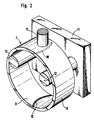
- FIG. 2 shows an inner roller bearing race 7 with a seat surface 8 and a race surface 9, which is to be provided with explosive joints at two diametrically opposite points on its circumference.
- a laser beam was applied to the seat surface 8 along the intended course 10 of the explosive joints.
- the inner rolling bearing race 7 is with its seat 8 on two starting from a frame 11 zen 12 mounted and can be acted upon by a plunger 13 on its tread 9 with a compressive force. 2, the inner roller bearing race 7 is aligned with the plunger 13 in such a way that the line of action of the compressive force runs through the area of the seat surface 8 which is acted upon by the laser beam, so that the latter is subjected to tensile force during the blasting.
- the explosive joint can have any shape. For example, it can run in the direction of the longitudinal axis or also inclined to it. It can also be arched or arrow-shaped.
Landscapes
- Engineering & Computer Science (AREA)
- Chemical & Material Sciences (AREA)
- Mechanical Engineering (AREA)
- General Engineering & Computer Science (AREA)
- Materials Engineering (AREA)
- Crystallography & Structural Chemistry (AREA)
- Physics & Mathematics (AREA)
- Metallurgy (AREA)
- Organic Chemistry (AREA)
- Thermal Sciences (AREA)
- Manufacturing & Machinery (AREA)
- Rolling Contact Bearings (AREA)
- Heat Treatment Of Articles (AREA)
Claims (3)
Applications Claiming Priority (2)
| Application Number | Priority Date | Filing Date | Title |
|---|---|---|---|
| DE3614246 | 1986-04-26 | ||
| DE19863614246 DE3614246A1 (de) | 1986-04-26 | 1986-04-26 | Verfahren zum herstellen eines an wenigstens einer stelle seines umfanges eine durchgehende sprengfuge aufweisenden waelzlagerlaufringes |
Publications (2)
| Publication Number | Publication Date |
|---|---|
| EP0243578A1 EP0243578A1 (fr) | 1987-11-04 |
| EP0243578B1 true EP0243578B1 (fr) | 1990-12-12 |
Family
ID=6299641
Family Applications (1)
| Application Number | Title | Priority Date | Filing Date |
|---|---|---|---|
| EP87100776A Expired - Lifetime EP0243578B1 (fr) | 1986-04-26 | 1987-01-21 | Procédé pour la fabrication d'une bague de palier à roulement comprenant un joint éclaté continu en au moins un endroit de sa périphérie |
Country Status (5)
| Country | Link |
|---|---|
| US (1) | US4821386A (fr) |
| EP (1) | EP0243578B1 (fr) |
| JP (1) | JPS62256919A (fr) |
| DE (2) | DE3614246A1 (fr) |
| ES (1) | ES2019586B3 (fr) |
Families Citing this family (22)
| Publication number | Priority date | Publication date | Assignee | Title |
|---|---|---|---|---|
| US5187345A (en) * | 1991-11-22 | 1993-02-16 | The Torrington Company | Method of welding retainer rings |
| DE19906436A1 (de) * | 1999-02-16 | 2000-08-17 | Bayerische Motoren Werke Ag | Bruchtrennbares Maschinen-Bauteil zur paßgenauen Wiedervereinigung über die Bruchtrennflächen, insbesondere einer lösbaren Wiedervereinigung |
| DE10022884B4 (de) * | 2000-05-10 | 2007-08-16 | Man Nutzfahrzeuge Ag | Verfahren zur Bruchtrennung in Bauteilen oder deren Vormaterial |
| US20050156004A1 (en) * | 2003-12-22 | 2005-07-21 | Edwards Mark S. | Method and apparatus for fracturing seal rings |
| EP2315958B1 (fr) * | 2008-09-04 | 2014-07-30 | Koyo Bearings USA, LLC | Procédé de fabrication d'une bague de palier divisée |
| DE102010062336A1 (de) * | 2010-12-02 | 2012-06-06 | Schaeffler Technologies Gmbh & Co. Kg | Bruchtrennverfahren |
| DE102011075549A1 (de) | 2011-05-10 | 2012-11-15 | Schaeffler Technologies AG & Co. KG | Verfahren zur Herstellung eines Lagerrings |
| USD866408S1 (en) | 2017-08-28 | 2019-11-12 | Qa1 Precision Products, Inc. | Shock absorber |
| USD872837S1 (en) | 2017-08-28 | 2020-01-14 | Qa1 Precision Products, Inc. | Bleed needle |
| US11085502B2 (en) | 2017-08-28 | 2021-08-10 | Qa1 Precision Products, Inc. | Bleed needle for a hydraulic system |
| US11105390B2 (en) | 2017-08-28 | 2021-08-31 | Qa1 Precision Products, Inc. | Shock absorber with dry valving |
| USD869259S1 (en) | 2017-08-28 | 2019-12-10 | Qa1 Precision Products, Inc. | Valve component |
| DE102019201565A1 (de) | 2019-02-07 | 2020-08-13 | Aktiebolaget Skf | Lagerkäfigsegment mit einer Stoßkante im Bereich eines zu bildenden Stegs |
| DE102019201553A1 (de) | 2019-02-07 | 2020-08-13 | Aktiebolaget Skf | Lagerkäfigsegment mit Ausrichtungselement |
| DE102019201554A1 (de) * | 2019-02-07 | 2020-08-13 | Aktiebolaget Skf | Lagerkäfigsegment mit Schweißmaterialstelle |
| DE102019201561A1 (de) | 2019-02-07 | 2020-08-13 | Aktiebolaget Skf | Lagerkäfigsegment eines Metallblechkäfigs |
| DE102019201560A1 (de) | 2019-02-07 | 2020-08-13 | Aktiebolaget Skf | Lagerkäfigsegment mit Stoßkante zum Verschweißen |
| DE102021206284A1 (de) | 2021-06-18 | 2022-12-22 | Aktiebolaget Skf | Käfigsegment für einen Wälzlagerkäfig |
| DE102021206282A1 (de) | 2021-06-18 | 2022-12-22 | Aktiebolaget Skf | Käfigsegment für einen Wälzlagerkäfig |
| DE102021206285A1 (de) | 2021-06-18 | 2022-12-22 | Aktiebolaget Skf | Käfigsegment für einen Wälzlagerkäfig |
| DE102022200327A1 (de) | 2022-01-13 | 2023-07-13 | Aktiebolaget Skf | Lagerkäfig |
| DE102022200326A1 (de) | 2022-01-13 | 2023-07-13 | Aktiebolaget Skf | Käfigsegment für einen Segmentkäfig |
Family Cites Families (8)
| Publication number | Priority date | Publication date | Assignee | Title |
|---|---|---|---|---|
| US2648578A (en) * | 1949-04-02 | 1953-08-11 | Split Ballbearing Corp | Bearing and method of making same |
| US2624105A (en) * | 1951-05-15 | 1953-01-06 | Torrington Co | Method of preparing and assembling antifriction bearings |
| US3884406A (en) * | 1972-06-08 | 1975-05-20 | Torrington Co | Fractured bearing race |
| FR2438686A1 (fr) * | 1978-10-13 | 1980-05-09 | France Etat | Procede de fragilisation par bombardement electronique |
| DE2947091C2 (de) * | 1979-11-22 | 1984-05-24 | Skf Kugellagerfabriken Gmbh, 8720 Schweinfurt | Verfahren zur Herstellung von längs einer pfeilförmigen Trennfuge gesprengten Lagerringen für Wälzlager o.dgl. |
| DE3120655C2 (de) * | 1981-05-23 | 1983-12-29 | INA Wälzlager Schaeffler KG, 8522 Herzogenaurach | Geschlitzter Kolbenring und Verfahren zu seiner Herstellung |
| DE3425829C2 (de) * | 1983-07-21 | 1987-01-22 | INA Wälzlager Schaeffler KG, 8522 Herzogenaurach | Verfahren zum Herstellen eines mit einer Sprengfuge versehenen Bauteils, insbesondere Wälzlagerlaufringes |
| JPS6039128A (ja) * | 1983-07-21 | 1985-02-28 | イナ・ベルツラーゲル・シエツフレル・コマンデイートゲゼルシヤフト | 拡開継目を備えた構成部材を製作する方法 |
-
1986
- 1986-04-26 DE DE19863614246 patent/DE3614246A1/de not_active Withdrawn
-
1987
- 1987-01-21 DE DE8787100776T patent/DE3766645D1/de not_active Expired - Lifetime
- 1987-01-21 ES ES87100776T patent/ES2019586B3/es not_active Expired - Lifetime
- 1987-01-21 EP EP87100776A patent/EP0243578B1/fr not_active Expired - Lifetime
- 1987-03-25 US US07/030,695 patent/US4821386A/en not_active Expired - Fee Related
- 1987-04-23 JP JP62098781A patent/JPS62256919A/ja active Pending
Also Published As
| Publication number | Publication date |
|---|---|
| EP0243578A1 (fr) | 1987-11-04 |
| DE3614246A1 (de) | 1987-10-29 |
| US4821386A (en) | 1989-04-18 |
| JPS62256919A (ja) | 1987-11-09 |
| ES2019586B3 (es) | 1991-07-01 |
| DE3766645D1 (de) | 1991-01-24 |
Similar Documents
| Publication | Publication Date | Title |
|---|---|---|
| EP0243578B1 (fr) | Procédé pour la fabrication d'une bague de palier à roulement comprenant un joint éclaté continu en au moins un endroit de sa périphérie | |
| DE2723928C2 (de) | Verfahren zur Herstellung eines an einer Stelle seines Umfangs gespaltenen Lagerrings | |
| DE4228237A1 (de) | Verfahren zum Herstellen eines Lagerringes | |
| DE8321186U1 (de) | Vorrichtung zum Befestigen von Maschinenteilen | |
| DE4042390C2 (de) | Gleichlauffestgelenk | |
| DE19740435A1 (de) | Verfahren zum Herstellen eines Käfigs | |
| EP0483660A2 (fr) | Rivet calibré pour assemblages rivés fortement sollicités | |
| DE3347503C2 (de) | Selbstsichernder Sperrbolzen | |
| DE19537209A1 (de) | Verfahren zum Herstellen von Synchronringen | |
| DE2609045A1 (de) | Mahltrommel | |
| DE2654439A1 (de) | Verfahren zur herstellung einer loesbaren steckverbindung und steckverbindung hergestellt nach dem verfahren | |
| DE1286497B (de) | Walzwerk zum Profilieren ringfoermiger Werkstuecke | |
| DE3425829C2 (de) | Verfahren zum Herstellen eines mit einer Sprengfuge versehenen Bauteils, insbesondere Wälzlagerlaufringes | |
| DE102005031335B4 (de) | Verfahren zum Herstellen von Bruchtrennkerben und Werkstück | |
| DE1934338A1 (de) | Vorrichtung zum Einbringen von Nuten in Metallteile | |
| DE102019116125A1 (de) | Projektil, insbesondere Deformations- und/oder Teilzerlegungsgeschoss, und Verfahren zum Herstellen eines Projektils | |
| EP0924442B1 (fr) | Coussinet et procédé de sa fabrication | |
| DE3120655A1 (de) | Geschlitzter kolbenring und verfahren zu seiner herstellung | |
| EP0340340B1 (fr) | Procédé pour la fabrication d'un trépan carottier diamanté | |
| DE3222116C1 (de) | Direkt gesteuertes Druckbegrenzungsventil | |
| DE3722913C2 (fr) | ||
| DE1810295A1 (de) | Spreizduebel | |
| DE1082087B (de) | Massiv-Fensterkaefig fuer Nadellager | |
| WO2006000463A1 (fr) | Procede pour separer par rupture une piece et piece separee selon le procede | |
| DE2252392A1 (de) | Schalthebel |
Legal Events
| Date | Code | Title | Description |
|---|---|---|---|
| PUAI | Public reference made under article 153(3) epc to a published international application that has entered the european phase |
Free format text: ORIGINAL CODE: 0009012 |
|
| 17P | Request for examination filed |
Effective date: 19870121 |
|
| AK | Designated contracting states |
Kind code of ref document: A1 Designated state(s): DE ES FR GB IT SE |
|
| 17Q | First examination report despatched |
Effective date: 19890911 |
|
| ITF | It: translation for a ep patent filed | ||
| GRAA | (expected) grant |
Free format text: ORIGINAL CODE: 0009210 |
|
| AK | Designated contracting states |
Kind code of ref document: B1 Designated state(s): DE ES FR GB IT SE |
|
| GBT | Gb: translation of ep patent filed (gb section 77(6)(a)/1977) | ||
| ET | Fr: translation filed | ||
| REF | Corresponds to: |
Ref document number: 3766645 Country of ref document: DE Date of ref document: 19910124 |
|
| ITTA | It: last paid annual fee | ||
| PLBE | No opposition filed within time limit |
Free format text: ORIGINAL CODE: 0009261 |
|
| STAA | Information on the status of an ep patent application or granted ep patent |
Free format text: STATUS: NO OPPOSITION FILED WITHIN TIME LIMIT |
|
| 26N | No opposition filed | ||
| PGFP | Annual fee paid to national office [announced via postgrant information from national office to epo] |
Ref country code: GB Payment date: 19921223 Year of fee payment: 7 |
|
| PGFP | Annual fee paid to national office [announced via postgrant information from national office to epo] |
Ref country code: FR Payment date: 19930113 Year of fee payment: 7 |
|
| PGFP | Annual fee paid to national office [announced via postgrant information from national office to epo] |
Ref country code: DE Payment date: 19930116 Year of fee payment: 7 |
|
| PGFP | Annual fee paid to national office [announced via postgrant information from national office to epo] |
Ref country code: SE Payment date: 19930118 Year of fee payment: 7 |
|
| PGFP | Annual fee paid to national office [announced via postgrant information from national office to epo] |
Ref country code: ES Payment date: 19930125 Year of fee payment: 7 |
|
| PG25 | Lapsed in a contracting state [announced via postgrant information from national office to epo] |
Ref country code: GB Effective date: 19940121 |
|
| PG25 | Lapsed in a contracting state [announced via postgrant information from national office to epo] |
Ref country code: SE Effective date: 19940122 Ref country code: ES Free format text: LAPSE BECAUSE OF NON-PAYMENT OF DUE FEES Effective date: 19940122 |
|
| GBPC | Gb: european patent ceased through non-payment of renewal fee |
Effective date: 19940121 |
|
| PG25 | Lapsed in a contracting state [announced via postgrant information from national office to epo] |
Ref country code: FR Effective date: 19940930 |
|
| PG25 | Lapsed in a contracting state [announced via postgrant information from national office to epo] |
Ref country code: DE Effective date: 19941001 |
|
| REG | Reference to a national code |
Ref country code: FR Ref legal event code: ST |
|
| EUG | Se: european patent has lapsed |
Ref document number: 87100776.1 Effective date: 19940810 |
|
| REG | Reference to a national code |
Ref country code: ES Ref legal event code: FD2A Effective date: 19990201 |
|
| PG25 | Lapsed in a contracting state [announced via postgrant information from national office to epo] |
Ref country code: IT Free format text: LAPSE BECAUSE OF NON-PAYMENT OF DUE FEES;WARNING: LAPSES OF ITALIAN PATENTS WITH EFFECTIVE DATE BEFORE 2007 MAY HAVE OCCURRED AT ANY TIME BEFORE 2007. THE CORRECT EFFECTIVE DATE MAY BE DIFFERENT FROM THE ONE RECORDED. Effective date: 20050121 |