EP0243415B1 - Zentrifuge - Google Patents
Zentrifuge Download PDFInfo
- Publication number
- EP0243415B1 EP0243415B1 EP86906267A EP86906267A EP0243415B1 EP 0243415 B1 EP0243415 B1 EP 0243415B1 EP 86906267 A EP86906267 A EP 86906267A EP 86906267 A EP86906267 A EP 86906267A EP 0243415 B1 EP0243415 B1 EP 0243415B1
- Authority
- EP
- European Patent Office
- Prior art keywords
- drum
- drum sleeve
- centrifuge according
- centrifuge
- solids
- Prior art date
- Legal status (The legal status is an assumption and is not a legal conclusion. Google has not performed a legal analysis and makes no representation as to the accuracy of the status listed.)
- Expired - Lifetime
Links
- 239000007787 solid Substances 0.000 claims abstract description 22
- 239000007788 liquid Substances 0.000 claims abstract description 13
- 239000000463 material Substances 0.000 claims description 16
- 239000000203 mixture Substances 0.000 claims description 9
- 239000013013 elastic material Substances 0.000 claims description 3
- 230000002093 peripheral effect Effects 0.000 claims 1
- 239000011343 solid material Substances 0.000 abstract description 5
- 238000000605 extraction Methods 0.000 abstract 1
- 238000007373 indentation Methods 0.000 description 3
- 230000007246 mechanism Effects 0.000 description 3
- 238000000926 separation method Methods 0.000 description 3
- 239000000126 substance Substances 0.000 description 3
- 239000010802 sludge Substances 0.000 description 2
- 238000005406 washing Methods 0.000 description 2
- 230000001133 acceleration Effects 0.000 description 1
- 230000006978 adaptation Effects 0.000 description 1
- 239000004744 fabric Substances 0.000 description 1
- 238000005243 fluidization Methods 0.000 description 1
- 239000006194 liquid suspension Substances 0.000 description 1
- 230000000737 periodic effect Effects 0.000 description 1
- 238000010334 sieve classification Methods 0.000 description 1
- 238000007873 sieving Methods 0.000 description 1
- 239000002759 woven fabric Substances 0.000 description 1
Images
Classifications
-
- B—PERFORMING OPERATIONS; TRANSPORTING
- B04—CENTRIFUGAL APPARATUS OR MACHINES FOR CARRYING-OUT PHYSICAL OR CHEMICAL PROCESSES
- B04B—CENTRIFUGES
- B04B7/00—Elements of centrifuges
- B04B7/08—Rotary bowls
- B04B7/18—Rotary bowls formed or coated with sieving or filtering elements
-
- B—PERFORMING OPERATIONS; TRANSPORTING
- B04—CENTRIFUGAL APPARATUS OR MACHINES FOR CARRYING-OUT PHYSICAL OR CHEMICAL PROCESSES
- B04B—CENTRIFUGES
- B04B3/00—Centrifuges with rotary bowls in which solid particles or bodies become separated by centrifugal force and simultaneous sifting or filtering
Definitions
- the invention relates to a centrifuge for separating solid-liquid mixtures, with a drum shell permeable to liquid and with a device for the axial transport of the solid from the mixture feed to the solid discharge.
- the invention has for its object to provide a simple centrifuge that is suitable for solid-liquid mixtures, such as. B. sludge, with high separation efficiency to drain continuously without having to apply the above-mentioned auxiliary measures for the axial transport of the solid.
- the drum jacket is flexible.
- One or more rollers, which do not co-rotate with the drum shell, are permanently pressed into the flexible drum shell from the outside, as a result of which each batch of the rotating drum shell is pressed in uniformly and the entire solid deposited is fluidized uniformly everywhere.
- the necessary axial transport movement of the solid in the drum shell is effected as in the case of a moving fluidized bed by fluidizing the solid while overcoming Coulomb's friction, which at the same time causes wear or damage
- Both on the drum casing and on the solid material to be treated are considerably reduced compared to previously known centrifuges, which had to work with screw conveyors, oscillating or pushing mechanisms.
- the transport speed of the goods through the drum jacket and thus the residence time of the goods in the centrifuge can also be controlled very well, e.g. B. by the indentation and / or the number of pressure rollers;
- the optimal dwell time or residence time of the material in the centrifuge can be optimally set and the scatter can be kept small by the set dwell time.
- a filter centrifuge is used for the pre-dewatering of moist and comparatively coarse-grained ore known (SU-A-1 002 028), which consists of a vehicle tire-like flexible and perforated rotating filter element into which pressure rollers can be pressed from the outside; however, in this known filter centrifuge, axial material transport in the rotating drum is not effected.
- the dwell time of the material to be dewatered in the rotating filter element is only about half the time of a complete revolution of the filter element, and it is therefore much too short to be able to dewater in particular sludges that are difficult to dewater.
- a relative movement between the sieve drum and the rotating pivoting levers for local denting of the sieve drum does not take place, nor is there a uniform fluidization of the entire solid material deposited on the inner wall of the sieve drum, so that the axial solids transport through this known centrifuge only in connection with the vertically hanging downward conically enlarged sieve drum is accessible.
- the feature of claim 2 of the invention can favor the axial transport of solids through the drum shell.
- the features of claim 3 allow a special type of axial material transport through the drum jacket.
- the features of claim 4 serve the possible adaptation of the material separation to the state of the substances at various points in the axial direction of the drum shell. Due to the features of claims 5 and 6, flexibility of the drum shell is achieved in the radial direction, in particular in the area of the two end disks. With the feature of claim 7, the transport speed of the goods can be controlled by the drum jacket. With the feature of claim 8, slippage between the drum shell and the pressure rollers can be prevented. With the features of claim 9, an overflow of liquid goods can be prevented in the drum jacket and the flow path of liquid goods can be extended and a liquid backlog can nevertheless be avoided.
- the feature of claim 10 allows easy access to the centrifuge according to the invention, for. B. for changing the drum shell.
- the flexible drum jacket of the centrifuge according to the invention can consist of a flexible grid, woven fabric, knitted fabric, perforated tube or the like. Blockages in the perforated drum jacket are avoided.
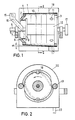
- Fig. 1 shows the drum shell (1), the feed-side face plate (2), the discharge-side face plate (3), the ring (4) made of elastic material, the shaft (5), shaft bearing (6), the frame (7) , a disc (8), stud bolts (9), flexible discs (10), openings (11) in the drum shell, intermediate rings (12), the drive disc (17) and the cone angle ⁇ .
- Fig. 2 shows the roller (13) in section, recesses (18) of the flexible discs (10), the hood (20) and the liquid drain (22).
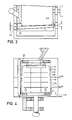
- Fig. 3 shows a roller (13), roller bearing (14) and the indentation s.
- Fig. 4 shows the embodiment of the invention with a floating shaft and inflatable rings (21).
- the material is moved continuously and controllably along the drum casing axially to the material discharge (11) from the material feed (15, 16).
- This invention finds application in the dewatering of solid / liquid suspensions, for the washing of disperse solids and for the sieving of disperse substances.
Landscapes
- Centrifugal Separators (AREA)
Description
- Die Erfindung betrifft eine Zentrifuge zum Trennen von Feststoff-Flüssigkeitsgemischen, mit einem für Flüssigkeit durchlässigen Trommelmantel und mit einer Einrichtung zum Axialtransport des Feststoffes von der Gemischaufgabe zum Feststoffaustrag.
- Bei kontinuierlich arbeitenden Zentrifugen zum Trennen von Feststoff-Flüssigkeitsgemischen, auch bei Siebmantelzentrifugen, bereitet der axial zum Zentrifugen-Trommelmantel verlaufende Axialtransport des Feststoffes von der Gemischaufgabe zum Feststoffaustrag Schwierigkeiten. Als bisher in der Praxis eingesetzte Einrichtungen zum Axialtransport des Feststoffes von der Gemischaufgabe zum Feststoffaustrag sind Förderschnecken bei Schneckenzentrifugen, Schwingantriebe bei Schwingzentrifugen oder Schubmechanismen bei Schubzentrifugen bekannt (Aufsatz "Kontinuierliche Zentrifugen zur Trennung fest/flüssig in der chemischen Industrie" in Zeitschrift Verfahrenstechnik 6 (1972), Seiten 7 bis 15). Alle diese zur axialen Transportbewegung des Feststoffes durch die Trommel einer kontinuierlich arbeitenden Zentrifuge notwendigen Hilfseinrichtungen sind aufwendig.
- Der Erfindung liegt die Aufgabe zugrunde, eine einfach gebaute Zentrifuge zu schaffen, die geeignet ist, Feststoff-Flüssigkeitsgemische, wie z. B. Schlämme, mit hoher Trennleistung kontinuierlich zu entwässern, ohne die obengenannten Hilfsmaßnahmen zum Axialtransport des Feststoffes anwenden zu müssen.
- Diese Aufgabe wird erfindungsgemäß gelöst mit den Maßnahmen des Kennzeichnungsteils des Anspruchs 1.
- Bei der erfindungsgemäßen Zentrifuge ist der Trommelmantel flexibel. In den flexiblen Trommelmantel sind von außen eine oder mehrere, mit dem Trommelmantel nicht mitrotierende Rollen permanent eingedrückt, wodurch jede Partie des rotierenden Trommelmantels gleichmäßig eingedrückt und der gesamte abgelagerte Feststoff gleichmäßig überall fluidisiert wird. Es hat sich nämlich überraschenderweise gezeigt, daß durch das Eindrücken des flexiblen Trommelmantels mittels der mindestens einen Andrückrolle der an der Innenwandung des Trommelmantels abgelagerte Feststoff im Bereich der Andrückrolle zunächst etwas angestaut und dann quasi losgelöst von der Mantelinnenwandung im Schwebezustand gehalten bzw. fluidisiert wird, so daß das Feststoffmaterial in diesem fluidisierten Zustand im Trommelmantel ideal eine translatorische Axialbewegung mitmachen kann, und zwar infolge des Fließdruckes, der durch den über die Gutaufgabe in den Trommelmantel einfließenden Gutstrom entsteht. Dies gilt auch für Zentrifugen mit zylindrischem Trommelmantel mit horizontaler Rotationsachse.
- Bei der erfindungsgemäßen Zentrifuge zum Trennen von Feststoff-Flüssigkeitsgemischen wird also die notwendige axiale Transportbewegung des Feststoffes im Trommelmantel wie bei einem bewegten Fließbett durch eine Fluidisierung des Feststoffs unter Überwindung der Coulomb'schen Reibung bewirkt, wodurch gleichzeitig bewirkt wird, daß der Verschleiß bzw. Beschädigungen sowohl am Trommelmantel als auch am zu behandelnden Feststoffmaterial gegenüber bisher bekannten Zentrifugen, die mit Förderschnecken, Schwing- oder Schubmechanismen arbeiten mußten, erheblich reduziert sind.
- Bei der erfindungsgemäßen Zentrifuge ist außerdem die Transportgeschwindigkeit des Gutes durch den Trommelmantel und damit die Verweilzeit des Gutes in der Zentrifuge sehr gut steuerbar, z. B. durch die Eindrücktiefe und/oder die Anzahl der Andrückrollen; je nach Schlammtyp läßt sich die optimale Verweilzeit bzw. Aufenthaltszeit des Gutes in der Zentrifuge optimal einstellen und die Streuung um die eingestellte Verweilzeit klein halten. Dies alles war bisher nur möglich durch den Einsatz der oben bereits erwähnten Förderschnecken bzw. Schwing- oder Schubmechanismen, wohingegen bei der Erfindung solche Hilfseinrichtungen gänzlich wegfallen.
- Zwar ist eine zur Vorentwässerung von feuchtem und vergleichsweise grobkörnigem Erz dienende Filterzentrifuge bekannt (SU-A-1 002 028), die aus einem fahrzeugreifenähnlichen flexiblen und perforierten rotierenden Filterelement besteht, in welches von außen Andrückrollen eindrückt werden können; jedoch wird bei dieser bekannten Filterzentrifuge ein axialer Guttransport in der rotierenden Trommel nicht bewirkt. Bei der bekannten Filterzentrifuge beträgt die Verweilzeit des zu entwässernden Gutes im rotierenden Filterelement nur etwa die Hälfte der Zeit einer ganzen Umdrehung des Filterelementes, und sie ist daher viel zu kurz, um insbesondere schwierig zu entwässernde Schlämme entwässern zu können. Bei einer ferner bekannten Siebzentrifuge (DE-A-12 88 989) sind an mehreren Umfangsstelle bzw. Mantellinien der Siebtrommel mit dieser mitrotierende Schwenkhebel befestigt, durch deren periodisches Verschwenken das elastische Material der Siebtrommel periodisch örtlich verformbar ist. Bei dieser bekannten Zentrifuge werden nur bestimmte Zonen der Siebtrommel elastisch verformt, nämlich die Zonen, an denen die Siebtrommel an den Schwenkhebeln befestigt ist, und auch diese Zonen werden nicht permanent, sondern nur periodisch verformt. Das heißt, bei der bekannten Zentrifuge erfolgt die Ablösung des Feststoffes von der Innenwandung der Siebtrommel primär nur an den Umfangsstellen, an denen die mitrotierenden Schwenkhebel an der Siebtrommel befestigt sind. Eine Relativbewegung zwischen der Siebtrommel und den mitrotierenden Schwenkhebeln zum örtlichen Einbeulen der Siebtrommel findet nicht statt, ebenso nicht eine gleichmäßige Fluidisierung des gesamten an der Siebtrommelinnenwandung abgelagerten Feststoffmateriales, so daß der axiale Feststofftransport durch diese bekannte Zentrifuge nur in Verbindung mit der vertikal hängenden, nach unten konisch erweiterten Siebtrommel erreichbar ist.
- Das Merkmal des Anspruchs 2 der Erfindung kann den axialen Feststofftransport durch den Trommelmantel begünstigen. Die Merkmale des Anspruchs 3 lassen eine besondere Art des axialen Guttransportes durch den Trommelmantel zu. Die Merkmale des Anspruchs 4 dienen der möglichen Anpassung der Stofftrennung an den Zustand der Stoffe an verschiedenen Stellen in axialer Richtung des Trommelmantels. Durch die Merkmale der Ansprüche 5 und 6 wird eine Nachgiebigkeit des Trommelmantels in radialer Richtung insbesondere im Bereich der beiden Stirnscheiben erreicht. Mit dem Merkmal des Anspruchs 7 kann die Transportgeschwindigkeit des Gutes durch den Trommelmantel gesteuert werden. Mit dem Merkmal des Anspruchs 8 kann ein Schlupf zwischen dem Trommelmantel und den Andrückrollen verhindert werden. Mit den Merkmalen des Anspruchs 9 kann im Trommelmantel ein Überströmen flüssigen Gutes verhindert und der Fließweg von flüssigem Gut verlängert und dennoch ein Flüssigkeitsstau vermieden werden. Das Merkmal des Anspruchs 10 ermöglicht eine gute Zugänglichkeit zur erfindungsgemäßen Zentrifuge, z. B. zwecks Wechsels des Trommelmantels.
- Der flexible Trommelmantel der erfindungsgemäßen Zentrifuge kann aus einem flexiblen Gitter, Gewebe, Gewirke, perforiertem Schlauch oder dergleichen bestehen. Verstopfungen des perforierten Trommelmantels sind vermieden.
- Die Erfindung und deren weitere Merkmale und Vorteile werden anhand der in den Figuren schematisch dargestellten Ausführungsbeispiele näher erläutert.
- Fig. 1 zeigt den Trommelmantel (1), die aufgabeseitige Stirnscheibe (2), die austragsseitige Stirnscheibe (3), den aus elastischem Werkstoff bestehenden Ring (4), die Welle (5), Wellenlager (6), den Rahmen (7), eine Scheibe (8), Stehbolzen (9), flexible Scheiben (10), Öffnungen (11) im Trommelmantel, Zwischenringe (12), die Antriebsscheibe (17) und den Kegelwinkel α.
- Fig. 2 zeigt die Rolle (13) im Schnitt, Ausnehmungen (18) der flexiblen Scheiben (10), die Haube (20) und den Flüssigkeitsablauf (22).
- Fig. 3 zeigt eine Rolle (13), Rollenlager (14) und die Eindrücktiefe s.
- Fig. 4 zeigt die Ausführung der Erfindung mit fliegend gelagerter Welle und aufblasbaren Ringen (21).
- Durch das permanente Eindrücken des Trommelmantels (1) wird das Gut von der Gutaufgabe (15, 16) stetig und steuerbar entlang des Trommelmantels axial zu dessen Gutaustrag (11) bewegt.
- Diese Erfindung findet Anwendung für das Entwässern von Fest/Flüssig-Suspensionen, zum Waschen von dispersen Feststoffen und zum Siebklassieren disperser Stoffe.
- Eine typische Ausführung der Erfindung zeigt etwa folgende Daten:
Trommeldurchmesser D = 0,2 - 1,5 m, Trommellänge L = 1 bis 3 D, Zentrifugalbeschleunigung z = 10 bis 1.000 g entspricht 100 bis 100.000 m/s², Anzahl der Rollen n = 1 bis 8, Rollendurchmesser d ≈ D/5, Kegelwinkel α = 2 bis 10°, Eindrücktiefe s der Rollen bei Anwendung als Entwässerungs- bzw. Wasch-Zentrifuge: s = 0,05 bis 0,1 d, für Siebklassieren: s = 0,1 bis 0,5 d.
Claims (10)
- Zentrifuge zum Trennen von Feststoff-Flüssigkeitsgemischen, mit einem für Flüssigkeit durchlässigen Trommelmantel und mit einer Einrichtung zum Axialtransport des Feststoffes von der Gemischaufgabe zum Feststoffaustrag, dadurch gekennzeichnet, daß der Trommelmantel (1) flexibel ist und daß die Einrichtung zum Axialtransport des Feststoffes aus einer oder mehreren von außen in den Trommelmantel (1) eingedrückten Rollen (13) besteht.
- Zentrifuge nach Anspruch 1, dadurch gekennzeichnet, daß der Trommelmantel (1) von der Gutaufgabe zum Gutaustrag kegelstumpfförmig erweitert ist.
- Zentrifuge nach Anspruch 1, dadurch gekennzeichnet, daß die Gutaufgabe (15, 16) in den Trommelmantel (1) durch dessen gutaufgabeseitige Stirnscheibe (2) angeordnet ist und daß zum Gutaustrag der Trommelmantel (1) Öffnungen (11) aufweist, die in Nähe der gutaustragsseitigen Stirnscheibe (3) angeordnet sind.
- Zentrifuge nach einem der Ansprüche 1 bis 3, dadurch gekennzeichnet, daß der Trommelmantel (1) in verschiedenen axialen Zonen verschieden große Maschen oder Öffnungen aufweist.
- Zentrifuge nach einem der Ansprüche 1 bis 4, dadurch gekennzeichnet, daß der Trommelmantel (1) auf Stirnscheiben (2 und 3) über zwischengeschaltete, in radialer Richtung nachgiebige Ringe (4) befestigt ist.
- Zentrifuge nach Anspruch 5, dadurch gekennzeichnet, daß die Ringe (4) aus elastischem Werkstoff bestehen und aufblasbar sind.
- Zentrifuge nach Anspruch 1, dadurch gekennzeichnet, daß die Rollen (13) verschieden tief in den Trommelmantel (1) eindrückbar sind bzw. eingedrückt werden.
- Zentrifuge nach den Ansprüchen 1 oder 7, dadurch gekennzeichnet, daß die Rollen (13) eine kegelstumpfförmige Form aufweisen.
- Zentrifuge nach einem oder mehreren der Ansprüche 1 bis 8, dadurch gekennzeichnet, daß im Innern des Trommelmantels (1) Scheiben (10) aus flexiblem Werkstoff vorhanden sind, die am Umfang Ausnehmungen (18) aufweisen können, wobei die Ausnehmungen (18) benachbarten Scheiben (10) in Umfangsrichtung versetzt sind.
- Zentrifuge nach einem oder mehreren der Ansprüche 1 bis 9, dadurch gekennzeichnet, daß die Welle (5) der Trommel (1) fliegend gelagert sind.
Priority Applications (1)
| Application Number | Priority Date | Filing Date | Title |
|---|---|---|---|
| AT86906267T ATE70741T1 (de) | 1985-10-23 | 1986-10-22 | Zentrifuge. |
Applications Claiming Priority (2)
| Application Number | Priority Date | Filing Date | Title |
|---|---|---|---|
| DE19853537662 DE3537662A1 (de) | 1985-10-23 | 1985-10-23 | Zentrifuge |
| DE3537662 | 1985-10-23 |
Publications (2)
| Publication Number | Publication Date |
|---|---|
| EP0243415A1 EP0243415A1 (de) | 1987-11-04 |
| EP0243415B1 true EP0243415B1 (de) | 1991-12-27 |
Family
ID=6284241
Family Applications (1)
| Application Number | Title | Priority Date | Filing Date |
|---|---|---|---|
| EP86906267A Expired - Lifetime EP0243415B1 (de) | 1985-10-23 | 1986-10-22 | Zentrifuge |
Country Status (4)
| Country | Link |
|---|---|
| EP (1) | EP0243415B1 (de) |
| AT (1) | ATE70741T1 (de) |
| DE (2) | DE3537662A1 (de) |
| WO (1) | WO1987002599A1 (de) |
Families Citing this family (2)
| Publication number | Priority date | Publication date | Assignee | Title |
|---|---|---|---|---|
| DE3905341A1 (de) * | 1988-03-30 | 1989-10-19 | Kloeckner Humboldt Deutz Ag | Zentrifugalapparat |
| NO3052245T3 (de) * | 2013-10-02 | 2018-05-12 |
Family Cites Families (2)
| Publication number | Priority date | Publication date | Assignee | Title |
|---|---|---|---|---|
| DE104829C (de) * | ||||
| DE1288989B (de) * | 1964-12-05 | 1969-02-06 | Rheta Rheinische Transportanla | Siebzentrifuge zur mechanischen Trennung der Komponenten eines aus Fluessigkeit und Feststoffen bestehenden Gemisches |
-
1985
- 1985-10-23 DE DE19853537662 patent/DE3537662A1/de not_active Withdrawn
-
1986
- 1986-10-22 AT AT86906267T patent/ATE70741T1/de not_active IP Right Cessation
- 1986-10-22 WO PCT/DE1986/000422 patent/WO1987002599A1/de not_active Ceased
- 1986-10-22 DE DE8686906267T patent/DE3683152D1/de not_active Expired - Fee Related
- 1986-10-22 EP EP86906267A patent/EP0243415B1/de not_active Expired - Lifetime
Non-Patent Citations (1)
| Title |
|---|
| Zeitschrift "Verfahrenstechnik" Nr. 6 (1972), Seiten 7 bis 15 * |
Also Published As
| Publication number | Publication date |
|---|---|
| WO1987002599A1 (fr) | 1987-05-07 |
| ATE70741T1 (de) | 1992-01-15 |
| DE3683152D1 (de) | 1992-02-06 |
| DE3537662A1 (de) | 1987-04-23 |
| EP0243415A1 (de) | 1987-11-04 |
Similar Documents
| Publication | Publication Date | Title |
|---|---|---|
| DE3248384C2 (de) | Einrichtung zur Entwässerung von Feststoffen | |
| DE2063516C3 (de) | Trommelsiebvorrichtung fur Faserstoff suspen sionen | |
| DE2343324A1 (de) | Filterpresse, insbesondere zur entwaesserung von schlamm in abwasserklaeranlagen | |
| EP0264899B1 (de) | Vorrichtung zum Entwässern von Schlamm und ähnlichen Substanzen | |
| DE2225231C3 (de) | Schneckenpresse | |
| EP0243415B1 (de) | Zentrifuge | |
| EP1194383A1 (de) | Vorrichtung zum entwässern von schlamm | |
| EP0435096B1 (de) | Flüssigkeits-Feststoff-Separator, insbesondere Gülleseparator | |
| CH660695A5 (de) | Doppel-schubzentrifuge. | |
| DE69011132T2 (de) | Schwingungserzeuger für zentrifugalsetzkasten. | |
| EP0331924B1 (de) | Schubzentrifuge | |
| DE2630639C3 (de) | Setzverfahren und -maschine zur Sortierung von Mineralkörnermischungen unterschiedlichen spezifischen Gewichts | |
| DE2208549B2 (de) | Verfahren und Vorrichtung zum Reinigen und Fraktionieren von Materialsuspensionen | |
| DE69014621T2 (de) | Kontinuierlich arbeitende filterzentrifuge. | |
| DE3546133C2 (de) | ||
| DE2150799C3 (de) | Siebvorrichtung für Saatgut u.dgl | |
| DE2651099A1 (de) | Schwingzentrifuge zum entwaessern von feinkoernigem gut | |
| DE3329648C2 (de) | Siebzentrifuge für kontinuierlichen Betrieb, insbesondere Zuckerzentrifuge | |
| EP0114296B1 (de) | Vorrichtung zum Abscheiden von Feststoffen aus einer Flüssigkeit, insbesondere Abwässern | |
| EP1468742A1 (de) | Mehrstufige Schubzentrifuge | |
| EP1468743A1 (de) | Schubzentrifuge | |
| EP0149151A1 (de) | Vorrichtung zum Beschleunigen der Stoffumsetzung zwischen zwei in einem Fliessbett reagierenden Medien | |
| DE2543289A1 (de) | Siebmaschine | |
| DE3622655A1 (de) | Dekantierzentrifuge | |
| DE1094191B (de) | Konische Siebtrommel und Verfahren zu ihrer Herstellung |
Legal Events
| Date | Code | Title | Description |
|---|---|---|---|
| PUAI | Public reference made under article 153(3) epc to a published international application that has entered the european phase |
Free format text: ORIGINAL CODE: 0009012 |
|
| AK | Designated contracting states |
Kind code of ref document: A1 Designated state(s): AT BE CH DE FR GB IT LI LU NL SE |
|
| 17P | Request for examination filed |
Effective date: 19871019 |
|
| 17Q | First examination report despatched |
Effective date: 19881207 |
|
| RAP1 | Party data changed (applicant data changed or rights of an application transferred) |
Owner name: KLOECKNER-HUMBOLDT-DEUTZ AKTIENGESELLSCHAFT |
|
| RIN1 | Information on inventor provided before grant (corrected) |
Inventor name: SCHMIDT, PAUL, PROF., DR. |
|
| GRAA | (expected) grant |
Free format text: ORIGINAL CODE: 0009210 |
|
| AK | Designated contracting states |
Kind code of ref document: B1 Designated state(s): AT BE CH DE FR GB IT LI LU NL SE |
|
| PG25 | Lapsed in a contracting state [announced via postgrant information from national office to epo] |
Ref country code: IT Free format text: LAPSE BECAUSE OF FAILURE TO SUBMIT A TRANSLATION OF THE DESCRIPTION OR TO PAY THE FEE WITHIN THE PRE;WARNING: LAPSES OF ITALIAN PATENTS WITH EFFECTIVE DATE BEFORE 2007 MAY HAVE OCCURRED AT ANY TIME BEFORE 2007. THE CORRECT EFFECTIVE DATE MAY BE DIFFERENT FROM THE ONE RECORDED.SCRIBED TIME-LIMIT Effective date: 19911227 Ref country code: FR Effective date: 19911227 Ref country code: GB Effective date: 19911227 Ref country code: SE Effective date: 19911227 |
|
| REF | Corresponds to: |
Ref document number: 70741 Country of ref document: AT Date of ref document: 19920115 Kind code of ref document: T |
|
| BECN | Be: change of holder's name |
Effective date: 19911227 |
|
| RAP2 | Party data changed (patent owner data changed or rights of a patent transferred) |
Owner name: KLOECKNER-HUMBOLDT-DEUTZ AG |
|
| REF | Corresponds to: |
Ref document number: 3683152 Country of ref document: DE Date of ref document: 19920206 |
|
| EN | Fr: translation not filed | ||
| GBV | Gb: ep patent (uk) treated as always having been void in accordance with gb section 77(7)/1977 [no translation filed] | ||
| PGFP | Annual fee paid to national office [announced via postgrant information from national office to epo] |
Ref country code: BE Payment date: 19921028 Year of fee payment: 7 Ref country code: DE Payment date: 19921028 Year of fee payment: 7 |
|
| PLBE | No opposition filed within time limit |
Free format text: ORIGINAL CODE: 0009261 |
|
| STAA | Information on the status of an ep patent application or granted ep patent |
Free format text: STATUS: NO OPPOSITION FILED WITHIN TIME LIMIT |
|
| PG25 | Lapsed in a contracting state [announced via postgrant information from national office to epo] |
Ref country code: LU Free format text: LAPSE BECAUSE OF NON-PAYMENT OF DUE FEES Effective date: 19921031 |
|
| PGFP | Annual fee paid to national office [announced via postgrant information from national office to epo] |
Ref country code: NL Payment date: 19921031 Year of fee payment: 7 |
|
| 26N | No opposition filed | ||
| PGFP | Annual fee paid to national office [announced via postgrant information from national office to epo] |
Ref country code: AT Payment date: 19930114 Year of fee payment: 7 |
|
| PGFP | Annual fee paid to national office [announced via postgrant information from national office to epo] |
Ref country code: CH Payment date: 19930119 Year of fee payment: 7 |
|
| PG25 | Lapsed in a contracting state [announced via postgrant information from national office to epo] |
Ref country code: AT Effective date: 19931022 |
|
| PG25 | Lapsed in a contracting state [announced via postgrant information from national office to epo] |
Ref country code: LI Effective date: 19931031 Ref country code: BE Effective date: 19931031 Ref country code: CH Effective date: 19931031 |
|
| BERE | Be: lapsed |
Owner name: KLOCKNER-HUMBOLDT-DEUTZ A.G. Effective date: 19931031 |
|
| PG25 | Lapsed in a contracting state [announced via postgrant information from national office to epo] |
Ref country code: NL Effective date: 19940501 |
|
| NLV4 | Nl: lapsed or anulled due to non-payment of the annual fee | ||
| REG | Reference to a national code |
Ref country code: CH Ref legal event code: PL |
|
| PG25 | Lapsed in a contracting state [announced via postgrant information from national office to epo] |
Ref country code: DE Effective date: 19940701 |