EP0243341A2 - Biopsieeinrichtung zur Gewinnung von Gewebeproben und Applikation von Substanzen in einem Arbeitsgang - Google Patents
Biopsieeinrichtung zur Gewinnung von Gewebeproben und Applikation von Substanzen in einem Arbeitsgang Download PDFInfo
- Publication number
- EP0243341A2 EP0243341A2 EP87890076A EP87890076A EP0243341A2 EP 0243341 A2 EP0243341 A2 EP 0243341A2 EP 87890076 A EP87890076 A EP 87890076A EP 87890076 A EP87890076 A EP 87890076A EP 0243341 A2 EP0243341 A2 EP 0243341A2
- Authority
- EP
- European Patent Office
- Prior art keywords
- biopsy
- channel
- application
- cannula
- wall
- Prior art date
- Legal status (The legal status is an assumption and is not a legal conclusion. Google has not performed a legal analysis and makes no representation as to the accuracy of the status listed.)
- Granted
Links
Images
Classifications
-
- A—HUMAN NECESSITIES
- A61—MEDICAL OR VETERINARY SCIENCE; HYGIENE
- A61B—DIAGNOSIS; SURGERY; IDENTIFICATION
- A61B10/00—Instruments for taking body samples for diagnostic purposes; Other methods or instruments for diagnosis, e.g. for vaccination diagnosis, sex determination or ovulation-period determination; Throat striking implements
- A61B10/02—Instruments for taking cell samples or for biopsy
- A61B10/0233—Pointed or sharp biopsy instruments
- A61B10/0283—Pointed or sharp biopsy instruments with vacuum aspiration, e.g. caused by retractable plunger or by connected syringe
-
- A—HUMAN NECESSITIES
- A61—MEDICAL OR VETERINARY SCIENCE; HYGIENE
- A61M—DEVICES FOR INTRODUCING MEDIA INTO, OR ONTO, THE BODY; DEVICES FOR TRANSDUCING BODY MEDIA OR FOR TAKING MEDIA FROM THE BODY; DEVICES FOR PRODUCING OR ENDING SLEEP OR STUPOR
- A61M5/00—Devices for bringing media into the body in a subcutaneous, intra-vascular or intramuscular way; Accessories therefor, e.g. filling or cleaning devices, arm-rests
- A61M5/14—Infusion devices, e.g. infusing by gravity; Blood infusion; Accessories therefor
- A61M5/158—Needles for infusions; Accessories therefor, e.g. for inserting infusion needles, or for holding them on the body
- A61M5/1582—Double lumen needles
-
- A—HUMAN NECESSITIES
- A61—MEDICAL OR VETERINARY SCIENCE; HYGIENE
- A61M—DEVICES FOR INTRODUCING MEDIA INTO, OR ONTO, THE BODY; DEVICES FOR TRANSDUCING BODY MEDIA OR FOR TAKING MEDIA FROM THE BODY; DEVICES FOR PRODUCING OR ENDING SLEEP OR STUPOR
- A61M25/00—Catheters; Hollow probes
- A61M25/0021—Catheters; Hollow probes characterised by the form of the tubing
- A61M25/0023—Catheters; Hollow probes characterised by the form of the tubing by the form of the lumen, e.g. cross-section, variable diameter
- A61M25/0026—Multi-lumen catheters with stationary elements
- A61M25/0032—Multi-lumen catheters with stationary elements characterized by at least one unconventionally shaped lumen, e.g. polygons, ellipsoids, wedges or shapes comprising concave and convex parts
Definitions
- the invention relates to a biopsy device for obtaining tissue samples and applying substances in one operation. It is known that there are various bioptical techniques for taking tissue samples from animal and human organs based on the principle of a single-channel needle with suction device and / or cutting device, with and without a trocar. Multi-lumen cannulas and needles are also known (DE-PS No. 818 246 and DE-OS 2643594), which, however, are not suitable for biopsy removal and substance application in one operation.
- suction biopsy is based on the principle given by Menghini (Menghini, G. 1957: Un effettivo progresso nella tecnica della puntura biopsia del fegato. Rass. Fisiopat. Clin. Ter. 29, 756).
- This is a hollow needle with an average diameter of 1.4 mm with a possible attachment for a syringe with which a negative pressure (suction) is applied after piercing the skin and before the actual organ puncture.
- the organ puncture liver then takes place in a fraction of a second with continued suction.
- the cutting biopsy is in principle carried out with a cannula ground at the front end.
- the cutting device and the lumen of the cannula are protected during the puncture process by a stylet inserted into the cannula lumen, which is removed after the puncture. Only then is a cylindrical piece of tissue cut out of the punctured organ under suction with a rotating, forward-directed movement (for example: Tru-Cut needle, Travenol company).
- Lung tissue cutting biopsies have a relatively high complication rate due to bleeding events and pneumothorax (McEvoy, RD, Begley, MD, Antic, R. 1983: Percutaneous Biopsy of Intrapulmonary Mass Lesions. Cancer 51, 2321).
- mesevoy, RD, Begley, MD, Antic, R. 1983 Percutaneous Biopsy of Intrapulmonary Mass Lesions. Cancer 51, 2321).
- the subsequent sealing of the puncture channel with resorbable material was recommended, in particular to prevent bleeding complications (Riley, SA, Irving, HC, Axon, ATR, Ellis, WR, Lintott, DJ, Losowsky MS 1984: Percutaneous liver biopsy with plugging the needle track: a safe method for use in patients with impaired coagulation. Lancet, Aug.
- the biopsy device is characterized in that a biopsy cannula is provided which extends over its longitudinal extent to form a biopsy channel and one or more
- the application channels are designed with two or more lumens, with at least the transverse diameter of the biopsy channel being retained over the entire length of the cannula and furthermore a cross section with respect to a longitudinal plane having the full cannula diameter, the inner limitation of the cannula lumens being provided by a partition wall which continuously merges into the outer cannula wall takes place so that the biopsy channel does not have any corners or edges that impair the quality of the tissue sample, and furthermore biopsy and application channels or application channels communicate with one another in the area of the cannula tip, and furthermore there are connection options for suction and application devices at the proximal end of the cann
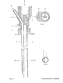
- FIG. 1 shows a longitudinal section through a two-channel needle
- FIG. 3 shows a cross section in the area of the two-channel needle along line B in FIG. 1
- FIG. 2 shows a cross section of the two-channel needle in the area of the attachment devices for generating a positive and / or negative pressure
- FIG. 4 shows a front view of the two-channel version
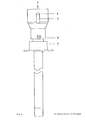
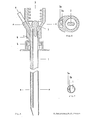
- FIG. 5 shows a longitudinal section of a three-channel needle
- FIG. 7 shows a cross section in the region of the three-channel needle along line B of FIG. 5
- FIG. 6 shows a cross section the three-channel needle in the area of the attachment devices along the line A of FIG. 5
- FIG. 8 is a front view of the three-channel version.
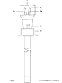
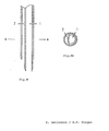
- Fig. 9 shows the longitudinal section
- Fig. 10 shows the cross section in line B-B of the cutting end of a two-channel needle.
- the puncture needle consists of a biopsy channel -1-, which also records the largest cross-sectional diameter of the needle.
- the separation from the application channel -2- or from the application channels -2a, 2b- is carried out by a partition -9- in such a way that there are no corners and edges in the biopsy channel -1- which could impair the quality of the tissue samples.
- a smaller space of the puncture needle, which is separated from the main channel, functions as the application channel.
- the channels can also be separated, for example, by two thin-walled tubes (Fig. 9, Fig. 10) that are adapted to one another and eccentrically pushed into one another. In the examples shown in FIG. 1 to FIG.
- the partition wall -9- between the biopsy channel -1- and the application channel -2- or application channels - 2 a, 2 b- does not reach as far as the cutting end of the cannula, so that the biopsy channel -1- and application channel (channels) -2, 2 a, 2 b- are connected to each other in the area of the needle tip.
- the outer wall of the application channel -2- or the application channels -2 a, 2 b- is directed inward in the area of the tip, so that the cutting end extends to the course of the biopsy channel -1-.
- the needle is ground according to the usual guidelines for suction or cutting biopsies.
- FIG. 10 The embodiment of the biopsy apparatus corresponding to the longitudinal section, and 9 shown in the Figure in -.
- Cross-section shown in Fig 10 on the line BB of F ig.. 9 shows that the cutting end is formed solely by the biopsy channel -1- ending at right angles to the longitudinal axis, the wall of which is ground at an acute angle, and that the application channel -2- formed by an eccentrically pushed tube over the wall of the biopsy needle does not reach the cutting end and the latter Wall is ground at an obtuse angle, so that a smooth transition of the outer wall of the biopsy channel -1- into the outer wall of the application channel -2- is effected in the section in which both channels touch.
- a bolt -7- which does not completely close the lumen of the needle and which is used to aspirate the tissue sample into the vacuum system which can be connected at -3- (for example syringe with locking) prevented.
- -4- represents the starting point for an application system whose arrangement and design (for example cone, thread etc.) can be adapted to the respective requirements (for example a system under pressure).
- the puncture depth is limited and the application system is controlled by a mechanism mounted on the needle, consisting of a part -6- attached to the cannula and having one or more contact points and a movable part - 5- having one or more contact points, which is operated by a spring -8- is held in the starting position.
- part -5- After reaching a certain puncture depth, part -5- is moved towards part -6- after contact with the body surface until the stop is reached and the contact is closed.
- the number of arrangement of contact points can be adapted to the requirements for controlling the application system.
- a mechanical system is also conceivable without changing the essence of the invention.
- the puncture is carried out according to the Menghini technique, in which, after piercing the skin, a negative pressure is created with the aid of a lockable syringe attached to the -3- position.
- the needle is then further inserted into the tissue (organ) to be punctured. After reaching the stop -5-, the needle is withdrawn immediately.
- substances for example blood coagulation substances, vasoactive pharmaceuticals, cytostatics, antibiotics etc.
- the design enables tissue removal and application of substances coordinated with the puncture procedure in one operation. As a result, the duration of the intervention is greatly reduced compared to previously known methods cuts.
- the arrangement of the channels ensures, despite the presence of additional channels, a minimum overall cannula diameter with a constant quality of the tissue sample taken for the histological diagnosis.
- this needle enables the puncture channel to be easily sealed with coagulation-active substances.
- the indications for punctures can be significantly expanded, which means improved diagnostics and therapy.
Landscapes
- Health & Medical Sciences (AREA)
- Life Sciences & Earth Sciences (AREA)
- Animal Behavior & Ethology (AREA)
- General Health & Medical Sciences (AREA)
- Biomedical Technology (AREA)
- Heart & Thoracic Surgery (AREA)
- Veterinary Medicine (AREA)
- Engineering & Computer Science (AREA)
- Public Health (AREA)
- Hematology (AREA)
- Vascular Medicine (AREA)
- Anesthesiology (AREA)
- Pathology (AREA)
- Medical Informatics (AREA)
- Molecular Biology (AREA)
- Surgery (AREA)
- Surgical Instruments (AREA)
Abstract
Description
- Die Erfindung betrifft eine Biopsieeinrichtung zur Gewinnung von Gewebsproben und Applikation von Substanzen in einem Arbeitsgang. Es ist bekannt, daß zur Entnahme von Gewebsproben aus tierischen und menschlichen Organen verschiedene bioptische Techniken auf dem Prinzip einer Einkanalnadel mit Saugvorrichtung und/oder Schneidvorrichtung, mit und ohne Trokar existieren. Bekannt sind weiters mehrlumige Kanülen und Nadeln (DE-PS Nr. 818 246 und DE-OS 2643594), die für eine Biopsieentnahme und Substanzapplikation in einem Arbeitsgang allerdings nicht geeignet sind.
- Zur Saugbiopsie ist zu bemerken: Die bekannteste Saugbiopsietechnik basiert auf dem von Menghini angegebenen Prinzip (Menghini, G. 1957: Un effettivo progresso nella tecnica della puntura biopsia del fegato. Rass. Fisiopat. clin. Ter. 29, 756). Dabei handelt es sich um eine im Durchschnitt 1,4 mm im Durchmesser haltende Hohlnadel mit einer Ansatzmöglichkeit für eine Spritze, mit der nach Durchstechen der Haut und vor der eigentlichen Organpunktion ein negativer Druck (Sog) angelegt wird. Die Organpunktion (Leber) erfolgt dann bei anhaltendem Sog im Bruchteil einer Sekunde.
- Zur Schneidbiopsie ist zu bemerken: Die Schneidbiopsie erfolgt im Prinzip mit einer am vorderen Ende zugeschliffenen Kanüle. Schneidvorrichtung und Lumen der Kanüle sind während des Punktionsvorganges durch ein in das Kanülenlumen eingelegtes Stilet geschützt, das nach der Punktion entfernt wird. Erst dann wird aus dem punktierten Organ unter Sogwirkung bei drehender, vorwärts gerichteter Bewegung ein zylindrisches Gewebsstück herausgeschnitten (zum Beispiel: Tru-Cut Nadel, Firma Travenol).
- Bei allen derzeit üblichen bioptischen Techniken muß mit Komplikationen gerechnet werden, die von der Art der Punktion (wie dem zu punktierenden Organ und der angewandten Technik) und vom Allgemeinzustand des Patienten abhängen. Die Hauptkomplikationen bei der Saugbiopsie der Leber stellen in erster Linie starke Blutungen, gallige Bauchfellentzündungen und der Pneumothorax dar (Lindner, H. 1967: Grenzen und Gefahren der perkutanen Leberbiopsie mit der Menghini-Nadel. Dtsch.med.Wschr. 39, 1751; Piccinino, F., Sagnelli E., Pasguale, G., Giusti G. 1986: Complications following percutaneous liver biopsy. J. Hepatology 2, 165). Schneidbiopsien vom Lungengewebe weisen eine relativ hohe Komplikationsrate durch Blutungsereignisse und Pneumothorax auf (McEvoy, R.D., Begley, M.D., Antic, R. 1983: Percutaneous Biopsy of Intrapulmonary Mass Lesions. Cancer 51, 2321). Auch für Nierenbiopsien und Biopsien anderer Organe gilt in erster Linie eine schwere Blutung als bedeutendste Komplikation. Um diesen Komplikationen zu begegnen, wurde die anschließende Plombierung des Stichkanales mit resorbierbarem Material empfohlen, um insbesondere Blutungskomplikationen hintanzuhalten (Riley, S.A., Irving, H.C., Axon, A.T.R., Ellis, W.R., Lintott, D.J., Losowsky M.S. 1984: Percutaneous liver biopsy with plugging the needle track: a safe method for use in patients with impaired coagulation. Lancet, Aug. 25 1984, 436). Derartige Techniken setzen aber eine lange Verweildauer der Punktionsnadel im Organ voraus, was insbesondere bei Leberpunktionen eine neuerliche Ursache für Komplikationen darstellt (Thaler, H. 1982: Leberbiopsie. Springer-Verlag. Heidelberg-New York).
- Zur Vermeidung der oben angeführten Komplikationen wurde gefunden, daß mit einer mehrkanäligen Biopsieeinrichtung sowohl die Entnahme von Gewebsproben als auch die Applikation von Substanzen in einem Arbeitsgang in kürzester Zeit (unter einer Sekunde) möglich ist. Die Biopsieeinrichtung ist erfindungsgemäß dadurch gekennzeichnet, daß eine Biopsiekanüle vorgesehen ist, die über ihre Längserstreckung zur Ausbildung eines Biopsiekanales und eines oder mehrerer Applikationskanäle zwei- oder mehrlumig ausgeführt ist, wobei zumindest der Querdurchmesser des Biopsiekanales über die gesamte Länge der Kanüle erhalten bleibt und weiters ein Querschnitt bezogen auf eine Längsebene den vollen Kanülendurchmesser aufweist, wobei die innere Begrenzung der Kanülenlumina durch eine kontinuierlich in die Kanülenaußenwand übergehende Trennwand erfolgt, sodaß der Biopsiekanal keine die Qualität der Gewebsprobe beeinträchtigenden Ecken oder Kanten aufweist, und weiters Biopsie- und Applikationskanal beziehungsweise Applikationskanäle im Bereich der Kanülenspitze miteinander kommunizieren, und ferner am proximalen Ende der Kanüle Anschlußmöglichkeiten für Saug- und Applikationsvorrichtungen bestehen.
- Drei Ausführungsbeispiele der Biopsieeinrichtung sind in den folgenden Zeichnungen dargestellt. Es zeigen Fig. 1 einen Längsschnitt durch eine Zweikanalpunktionsnadel, Fig. 3 einen Querschnitt im Bereich der Zweikanalnadel entlang der Linie B in Fig. 1, und Fig. 2 einen Querschnitt der Zweikanalnadel im Bereich der Ansatzvorrichtungen zur Erzeugung eines positiven und/oder negativen Druckes entlang der Linie A der Fig. 1 , Fig. 4 eine Vorderansicht der Zweikanal-Ausführung, Fig. 5 einen Längsschnitt einer Dreikanalpunktionsnadel, Fig. 7 einen Querschnitt im Bereich der Dreikanalnadel entlang der Linie B der Fig. 5, Fig. 6 einen Querschnitt der Dreikanalnadel im Bereich der Ansatzvorrichtungen entlang der Linie A der Fig. 5, Fig. 8 eine Vorderansicht der Dreikanalversion. Fig. 9 stellt den Längsschnitt, Fig. 10 den Querschnitt in der Linie B-B des schneidenden Endes einer Zweikanalnadel dar.
- Die Punktionsnadel besteht aus einem Biopsiekanal -1-, der den größten Nadelquerdurchmesser miterfaßt. Wie aus den Figuren 3 und 7 hervorgeht, erfolgt die Trennung gegenüber dem Applikationskanal -2- beziehungsweise gegenüber den Applikationskanälen -2 a, 2 b- durch -eine Trennwand -9- derart, daß im Biopsiekanal -1- keine Ecken und Kanten entstehen, die eine Qualitätsbeeinträchtigung der Gewebsproben bewirken könnten. Als Applikationskanal fungiert ein vom Hauptkanal abgetrennter kleinerer Raum der Punktionsnadel. Die Trennung der Kanäle kann zum Beispiel auch durch zwei aneinander angepaßte, exzentrisch ineinander geschobene dünnwandige Rohre ( Fig.9, Fig.10 ) bewirkt werden. In den in Fig.1 bis Fig.8 dargestellten Beispielen reicht die Trennwand -9- zwischen Biopsiekanal -1- und Applikationskanal -2- beziehungsweise Applikationskanäle - 2 a, 2 b- nicht bis unmittelbar an das schneidende Ende der Kanüle heran, sodaß Biopsiekanal -1- und Applikationskanal (-kanäle) -2, 2 a, 2 b- im Bereich der Nadelspitze miteinander in Verbindung stehen. Die Außenwand des Applikationskanales -2- beziehungsweise der Applikationskanäle -2 a, 2 b- ist im Bereich der Spitze nach innen gerichtet, sodaß das schneidende Ende bis an den Verlauf des Biopsiekanales -1- reicht. Der Schliff der Nadel erfolgt nach den für Saug- oder Schneidbiopsien üblichen Richtlinien.
- Das Ausführungsbeispiel der Biopsieeinrichtung entsprechend dem in Fig. 9 dargestellten Längsschnitt und dem in - Fig. 10 dargestellten Querschnitt in der Linie B-B von Fig. 9 zeigt, daß das schneidende Ende vom rechtwinkelig zur Längsachse endenden Biopsiekanal -1- alleine gebildet wird, dessen Wand spitzwinkelig geschliffen ist, und daß der durch ein exzentrisch über die Biopsienadelwand geschobenes Rohr entstandene Applikationskanal -2- nicht bis zum schneidenden Ende reicht und dessen Wand am Ende stumpfwinkelig geschliffen ist, sodaß ein fließender Übergang der Außenwand des Biopsiekanals -1- in die Außenwand des Applikationskanals -2- in dem Abschnitt, in dem sich beide Kanäle berühren, bewirkt wird.
- Am Ansatzende der Nadel ( Fig. 1,2,4,5,6,8 ) befindet sich ein das Lumen der Nadel nicht vollständig verschließender Bolzen -7-, der ein Absaugen der Gewebsprobe in das bei - 3- anschließbare Unterdrucksystem (zum Beispiel Spritze mit Arretierung) verhindert. -4- stellt die Ansatzmöglichkeit für ein Applikationssystem dar, dessen Anordnung und Gestaltung (zum Beispiel Konus, Gewinde etc.) an die jeweiligen Erfordernisse (zum Beispiel unter Druck stehendes System) angepaßt werden kann. Die Begrenzung der Punktionstiefe und die Steuerung des Applikationssystems erfolgt durch einen der Nadel aufsitzenden Mechanismus, bestehend aus einem an der Kanüle befestigten und einen oder mehrere Kontaktpunkte aufweisenden Teil -6- und einem oder mehrere Kontaktpunkte aufweisenden beweglichen Teil - 5-, der durch eine Feder -8- in Ausgangsstellung gehalten wird. Nach Erreichen einer bestimmten Punktionstiefe wird Teil -5- nach Berührung mit der Körperoberfläche in Richtung Teil -6- bewegt, bis der Anschlag erreicht ist und der Kontakt geschlossen wird. Die Zahl der Anordnung von Kontaktpunkten kann den Erfordernissen zur Steuerung des Applikationssystems angepaßt werden. Anstelle des skizzierten elektrischen Steuerungssystems ist auch ein mechanisches System vorstellbar, ohne daß dadurch das Wesen der Erfindung eine Änderung erfährt.
- Die Punktion erfolgt nach der Menghini-Technik, bei der nach Durchstechen der Haut ein Unterdruck mit Hilfe einer an der Stelle -3- angesetzten, arretierbaren Spritze erzeugt wird. Anschließend wird die Nadel weiter in das zu punktierende Gewebe (Organ) eingestochen. Nach Erreichen des Anschlages -5- wird die Nadel sofort zurückgezogen. Die Injektion von Substanzen (zum Beispiel Blutgerinnungssubstanzen, vasoaktive Pharmaka, Zytostatika, Antibiotika etc.) wird automatisch durch den Auslösemechanismus nach Erreichen einer vorbestimmbaren Einstichtiefe ausgelöst.
- Die Konstruktion ermöglicht eine Gewebsentnahme und eine mit dem Punktionsvorgang koordinierte Applikation von Substanzen in einem Arbeitsgang. Dadurch wird im Vergleich zu bisher bekannten Methoden die Eingriffsdauer stark verkürzt. Die Anordnung der Kanäle gewährleistet trotz des Vorhandenseins zusätzlicher Kanäle einen minimalen Kanülengesamtdurchmesser bei gleichbleibender Qualität der für die histologische Befundung entnommenen Gewebsprobe. Diese Nadel ermöglicht unter anderem die unkomplizierte Plombierung des Punktionskanales mit gerinnungsaktiven Substanzen. Die Indikationen für Punktionen können dadurch wesentlich erweitert werden, was eine verbesserte Diagnostik und Therapie bedeutet.
Claims (4)
Applications Claiming Priority (4)
| Application Number | Priority Date | Filing Date | Title |
|---|---|---|---|
| AT1041/86 | 1986-04-21 | ||
| AT104186A AT384165B (de) | 1986-04-21 | 1986-04-21 | Biopsieeinrichtung zur gewinnung von gewebeproben und applikation von substanzen in einem arbeitsgang |
| AT0091487A AT385890B (de) | 1987-04-13 | 1987-04-13 | Biopsieeinrichtung zur gewinnung von gewebsproben und applikation von substanzen in einem arbeitsgang |
| AT914/87 | 1987-04-13 |
Publications (3)
| Publication Number | Publication Date |
|---|---|
| EP0243341A2 true EP0243341A2 (de) | 1987-10-28 |
| EP0243341A3 EP0243341A3 (en) | 1990-01-17 |
| EP0243341B1 EP0243341B1 (de) | 1992-11-19 |
Family
ID=25594298
Family Applications (1)
| Application Number | Title | Priority Date | Filing Date |
|---|---|---|---|
| EP19870890076 Expired - Lifetime EP0243341B1 (de) | 1986-04-21 | 1987-04-15 | Biopsieeinrichtung zur Gewinnung von Gewebeproben und Applikation von Substanzen in einem Arbeitsgang |
Country Status (3)
| Country | Link |
|---|---|
| EP (1) | EP0243341B1 (de) |
| DE (1) | DE3782679D1 (de) |
| ES (1) | ES2036222T3 (de) |
Cited By (14)
| Publication number | Priority date | Publication date | Assignee | Title |
|---|---|---|---|---|
| EP0455626A1 (de) * | 1990-05-03 | 1991-11-06 | IMMUNO Aktiengesellschaft | Biopsieeinrichtung |
| EP0465458A1 (de) * | 1990-07-04 | 1992-01-08 | AVL Medical Instruments AG | Zweilumige Entnahmenadel für Körperflüssigkeiten |
| FR2703909A1 (fr) * | 1991-12-03 | 1994-10-21 | Hokama Yasuo | Aiguille d'injection intraveineuse à demeure, avec deux voies de passage pour le reflux du sang. |
| EP0632996A1 (de) * | 1993-07-09 | 1995-01-11 | Hossein Nabai | Hautbiopsievorrichtung und Methode |
| EP0829232A3 (de) * | 1996-08-29 | 1998-03-25 | City Of Hope | Minimal-invasive Biopsieeinrichtung |
| DE10026303A1 (de) * | 2000-05-26 | 2002-02-07 | Pajunk Gmbh | Biopsienadel |
| EP2095773A1 (de) * | 2008-02-27 | 2009-09-02 | Ethicon Endo-Surgery, Inc. | Biopsiesonde mit Injektionslumen |
| US20150305721A1 (en) * | 2012-11-30 | 2015-10-29 | National Cancer Center | Biotissue sampling apparatus |
| US9636082B2 (en) | 2001-08-24 | 2017-05-02 | The Cooper Companies Global Holdings Lp | Medical-surgical devices |
| US10045756B2 (en) | 2003-03-29 | 2018-08-14 | The Cooper Companies Global Holdings Lp | Medical devices |
| CN109171827A (zh) * | 2018-10-24 | 2019-01-11 | 杭州丽康医学科技股份有限公司 | 一种双通道同轴套管针 |
| CN109330635A (zh) * | 2018-07-27 | 2019-02-15 | 尚华 | 一种多功能的血管内组织穿刺针头及其应用方法 |
| CN113082369A (zh) * | 2015-10-28 | 2021-07-09 | 贝克顿·迪金森公司 | Iv导管系统 |
| US20220079672A1 (en) * | 2008-12-16 | 2022-03-17 | Nico Corporation | Tissue removal device with adjustable delivery sleeve for neurosurgical and spinal surgery applications |
Family Cites Families (3)
| Publication number | Priority date | Publication date | Assignee | Title |
|---|---|---|---|---|
| DE2643594A1 (de) * | 1975-10-06 | 1977-04-14 | Roger Beelen | Haemodialyse-nadel |
| DE3364080D1 (en) * | 1982-10-29 | 1986-07-17 | Miles Lab | Long indwelling double bore catheter |
| DE3522782A1 (de) * | 1985-06-26 | 1987-01-15 | Peter Brehm Chir Mechanik Werk | Doppellumige follikelpunktionskanuele |
-
1987
- 1987-04-15 ES ES87890076T patent/ES2036222T3/es not_active Expired - Lifetime
- 1987-04-15 DE DE8787890076T patent/DE3782679D1/de not_active Expired - Lifetime
- 1987-04-15 EP EP19870890076 patent/EP0243341B1/de not_active Expired - Lifetime
Cited By (25)
| Publication number | Priority date | Publication date | Assignee | Title |
|---|---|---|---|---|
| AT396548B (de) * | 1990-05-03 | 1993-10-25 | Immuno Ag | Biopsieeinrichtung |
| EP0455626A1 (de) * | 1990-05-03 | 1991-11-06 | IMMUNO Aktiengesellschaft | Biopsieeinrichtung |
| EP0623356B1 (de) * | 1990-07-04 | 1996-10-02 | AVL Medical Instruments AG | Zweilumige Entnahmenadel für Körperflüssigkeiten |
| EP0465458A1 (de) * | 1990-07-04 | 1992-01-08 | AVL Medical Instruments AG | Zweilumige Entnahmenadel für Körperflüssigkeiten |
| AT397911B (de) * | 1990-07-04 | 1994-08-25 | Avl Verbrennungskraft Messtech | Zweilumige entnahmenadel für körperflüssigkeiten |
| FR2703909A1 (fr) * | 1991-12-03 | 1994-10-21 | Hokama Yasuo | Aiguille d'injection intraveineuse à demeure, avec deux voies de passage pour le reflux du sang. |
| EP0632996A1 (de) * | 1993-07-09 | 1995-01-11 | Hossein Nabai | Hautbiopsievorrichtung und Methode |
| EP0829232A3 (de) * | 1996-08-29 | 1998-03-25 | City Of Hope | Minimal-invasive Biopsieeinrichtung |
| DE10026303A1 (de) * | 2000-05-26 | 2002-02-07 | Pajunk Gmbh | Biopsienadel |
| US9743904B2 (en) | 2001-08-24 | 2017-08-29 | The Cooper Companies Global Holdings Lp | Medico-surgical devices |
| US10478150B2 (en) | 2001-08-24 | 2019-11-19 | The Cooper Companies Global Holdings Lp | Medico—surgical devices |
| US9636082B2 (en) | 2001-08-24 | 2017-05-02 | The Cooper Companies Global Holdings Lp | Medical-surgical devices |
| US9642591B2 (en) | 2001-08-24 | 2017-05-09 | The Cooper Companies Global Holdings Lp | Medical-surgical devices |
| US10045756B2 (en) | 2003-03-29 | 2018-08-14 | The Cooper Companies Global Holdings Lp | Medical devices |
| US10639002B2 (en) | 2003-03-29 | 2020-05-05 | The Cooper Companies Global Holdings Lp | Medical devices |
| CN102973297A (zh) * | 2008-02-27 | 2013-03-20 | 德威科医疗产品公司 | 具有皮下腔的活检探头 |
| CN102973297B (zh) * | 2008-02-27 | 2015-09-02 | 德威科医疗产品公司 | 具有皮下腔的活检探头 |
| EP2095773A1 (de) * | 2008-02-27 | 2009-09-02 | Ethicon Endo-Surgery, Inc. | Biopsiesonde mit Injektionslumen |
| US20220079672A1 (en) * | 2008-12-16 | 2022-03-17 | Nico Corporation | Tissue removal device with adjustable delivery sleeve for neurosurgical and spinal surgery applications |
| US20150305721A1 (en) * | 2012-11-30 | 2015-10-29 | National Cancer Center | Biotissue sampling apparatus |
| US10695039B2 (en) * | 2012-11-30 | 2020-06-30 | National Cancer Center | Biotissue sampling apparatus |
| CN113082369A (zh) * | 2015-10-28 | 2021-07-09 | 贝克顿·迪金森公司 | Iv导管系统 |
| CN109330635A (zh) * | 2018-07-27 | 2019-02-15 | 尚华 | 一种多功能的血管内组织穿刺针头及其应用方法 |
| CN109330635B (zh) * | 2018-07-27 | 2024-02-06 | 尚华 | 一种多功能的血管内组织穿刺针头及其应用方法 |
| CN109171827A (zh) * | 2018-10-24 | 2019-01-11 | 杭州丽康医学科技股份有限公司 | 一种双通道同轴套管针 |
Also Published As
| Publication number | Publication date |
|---|---|
| EP0243341B1 (de) | 1992-11-19 |
| DE3782679D1 (de) | 1992-12-24 |
| EP0243341A3 (en) | 1990-01-17 |
| ES2036222T3 (es) | 1993-05-16 |
Similar Documents
| Publication | Publication Date | Title |
|---|---|---|
| US4850373A (en) | Biopsy device | |
| EP0263096B1 (de) | Vorrichtung und Verfahren zur Entnahme von Flüssigkeiten, Gewebe | |
| DE3917051C2 (de) | ||
| DE19909567B4 (de) | Vorrichtung und Verfahren zum Einschneiden | |
| DE69013367T2 (de) | Biopsiespritze. | |
| EP0243341B1 (de) | Biopsieeinrichtung zur Gewinnung von Gewebeproben und Applikation von Substanzen in einem Arbeitsgang | |
| DE69313510T2 (de) | Abgabekatheter | |
| DE69733836T2 (de) | Vorrichtung zur körperflüssigkeitsentnahme und -analyse | |
| DE69932612T2 (de) | Gerät zur erleichterten hemostase eines biopsietraktes | |
| DE2616533C3 (de) | Vorrichtung zur arteriellen Blutprobenentnahme | |
| DE19510455B4 (de) | Chirurgisches Instrument zum stoßartigen Einführen einer intraossären Trokarnadel | |
| DE2703087C2 (de) | Doppellumenkatheter | |
| EP1651114A1 (de) | Gerät für nadelbiopsie | |
| EP0221007B1 (de) | Feinnadel-Biopsiekanüle mit Mandrin | |
| DE112016000756T5 (de) | Vorrichtung zum Erzeugen eines lokalen Vakuums an einem distalen Ende einer Probennahmevorrichtunng | |
| DE19601214A1 (de) | Vorrichtung zur Abnahme von Blut | |
| DE3326648C2 (de) | Ballonkatheter | |
| DE3020926A1 (de) | Kanuele, insbesondere fuer die lumbalpunktion und -injektion | |
| DE3933373C2 (de) | ||
| DE19703921C1 (de) | Blutentnahmevorrichtung | |
| DE3417182A1 (de) | Spritzen-set | |
| AT384165B (de) | Biopsieeinrichtung zur gewinnung von gewebeproben und applikation von substanzen in einem arbeitsgang | |
| DE8623592U1 (de) | Vorrichtung zur Entnahme von Flüssigkeiten, Gewebe o.dgl. | |
| DE4020442C2 (de) | Vorrichtung zur Blutentnahme | |
| DE4320008A1 (de) | Biopsiekanüle |
Legal Events
| Date | Code | Title | Description |
|---|---|---|---|
| PUAI | Public reference made under article 153(3) epc to a published international application that has entered the european phase |
Free format text: ORIGINAL CODE: 0009012 |
|
| 17P | Request for examination filed |
Effective date: 19870507 |
|
| AK | Designated contracting states |
Kind code of ref document: A2 Designated state(s): BE CH DE ES FR GB GR IT LI LU NL SE |
|
| RAP1 | Party data changed (applicant data changed or rights of an application transferred) |
Owner name: DINGES, HANS PETER, DR. Owner name: IMMUNO AKTIENGESELLSCHAFT FUER CHEMISCH-MEDIZINISC |
|
| RIN1 | Information on inventor provided before grant (corrected) |
Inventor name: DINGES, HANS PETER, DR. Inventor name: ZATLOUKAL, KURT, DR. |
|
| RAP1 | Party data changed (applicant data changed or rights of an application transferred) |
Owner name: IMMUNO AKTIENGESELLSCHAFT FUER CHEMISCH-MEDIZINISC |
|
| PUAL | Search report despatched |
Free format text: ORIGINAL CODE: 0009013 |
|
| AK | Designated contracting states |
Kind code of ref document: A3 Designated state(s): BE CH DE ES FR GB GR IT LI LU NL SE |
|
| RAP1 | Party data changed (applicant data changed or rights of an application transferred) |
Owner name: IMMUNO AKTIENGESELLSCHAFT |
|
| 17Q | First examination report despatched |
Effective date: 19910515 |
|
| GRAA | (expected) grant |
Free format text: ORIGINAL CODE: 0009210 |
|
| AK | Designated contracting states |
Kind code of ref document: B1 Designated state(s): BE CH DE ES FR GB GR IT LI LU NL SE |
|
| PG25 | Lapsed in a contracting state [announced via postgrant information from national office to epo] |
Ref country code: GR Free format text: LAPSE BECAUSE OF FAILURE TO SUBMIT A TRANSLATION OF THE DESCRIPTION OR TO PAY THE FEE WITHIN THE PRESCRIBED TIME-LIMIT Effective date: 19921119 |
|
| REF | Corresponds to: |
Ref document number: 3782679 Country of ref document: DE Date of ref document: 19921224 |
|
| ITF | It: translation for a ep patent filed | ||
| ET | Fr: translation filed | ||
| GBT | Gb: translation of ep patent filed (gb section 77(6)(a)/1977) |
Effective date: 19930216 |
|
| PG25 | Lapsed in a contracting state [announced via postgrant information from national office to epo] |
Ref country code: LU Free format text: LAPSE BECAUSE OF NON-PAYMENT OF DUE FEES Effective date: 19930430 |
|
| REG | Reference to a national code |
Ref country code: ES Ref legal event code: FG2A Ref document number: 2036222 Country of ref document: ES Kind code of ref document: T3 |
|
| PLBE | No opposition filed within time limit |
Free format text: ORIGINAL CODE: 0009261 |
|
| STAA | Information on the status of an ep patent application or granted ep patent |
Free format text: STATUS: NO OPPOSITION FILED WITHIN TIME LIMIT |
|
| 26N | No opposition filed | ||
| EAL | Se: european patent in force in sweden |
Ref document number: 87890076.0 |
|
| REG | Reference to a national code |
Ref country code: GB Ref legal event code: IF02 |
|
| PGFP | Annual fee paid to national office [announced via postgrant information from national office to epo] |
Ref country code: FR Payment date: 20060417 Year of fee payment: 20 |
|
| PGFP | Annual fee paid to national office [announced via postgrant information from national office to epo] |
Ref country code: GB Payment date: 20060424 Year of fee payment: 20 |
|
| PGFP | Annual fee paid to national office [announced via postgrant information from national office to epo] |
Ref country code: SE Payment date: 20060426 Year of fee payment: 20 Ref country code: CH Payment date: 20060426 Year of fee payment: 20 |
|
| PGFP | Annual fee paid to national office [announced via postgrant information from national office to epo] |
Ref country code: IT Payment date: 20060430 Year of fee payment: 20 |
|
| PGFP | Annual fee paid to national office [announced via postgrant information from national office to epo] |
Ref country code: BE Payment date: 20060516 Year of fee payment: 20 |
|
| PGFP | Annual fee paid to national office [announced via postgrant information from national office to epo] |
Ref country code: NL Payment date: 20060524 Year of fee payment: 20 |
|
| PGFP | Annual fee paid to national office [announced via postgrant information from national office to epo] |
Ref country code: ES Payment date: 20060526 Year of fee payment: 20 |
|
| PGFP | Annual fee paid to national office [announced via postgrant information from national office to epo] |
Ref country code: DE Payment date: 20060531 Year of fee payment: 20 |
|
| PG25 | Lapsed in a contracting state [announced via postgrant information from national office to epo] |
Ref country code: NL Free format text: LAPSE BECAUSE OF EXPIRATION OF PROTECTION Effective date: 20070415 |
|
| PG25 | Lapsed in a contracting state [announced via postgrant information from national office to epo] |
Ref country code: ES Free format text: LAPSE BECAUSE OF EXPIRATION OF PROTECTION Effective date: 20070416 |
|
| REG | Reference to a national code |
Ref country code: GB Ref legal event code: PE20 |
|
| REG | Reference to a national code |
Ref country code: CH Ref legal event code: PL |
|
| NLV7 | Nl: ceased due to reaching the maximum lifetime of a patent |
Effective date: 20070415 |
|
| EUG | Se: european patent has lapsed | ||
| REG | Reference to a national code |
Ref country code: ES Ref legal event code: FD2A Effective date: 20070416 |
|
| PG25 | Lapsed in a contracting state [announced via postgrant information from national office to epo] |
Ref country code: GB Free format text: LAPSE BECAUSE OF EXPIRATION OF PROTECTION Effective date: 20070414 |
|
| BE20 | Be: patent expired |
Owner name: *IMMUNO A.G. Effective date: 20070415 |