EP0242648A2 - Inking unit for a planographic rotary printing machine - Google Patents
Inking unit for a planographic rotary printing machine Download PDFInfo
- Publication number
- EP0242648A2 EP0242648A2 EP87104792A EP87104792A EP0242648A2 EP 0242648 A2 EP0242648 A2 EP 0242648A2 EP 87104792 A EP87104792 A EP 87104792A EP 87104792 A EP87104792 A EP 87104792A EP 0242648 A2 EP0242648 A2 EP 0242648A2
- Authority
- EP
- European Patent Office
- Prior art keywords
- roller
- inking unit
- stamp
- unit according
- holder
- Prior art date
- Legal status (The legal status is an assumption and is not a legal conclusion. Google has not performed a legal analysis and makes no representation as to the accuracy of the status listed.)
- Withdrawn
Links
Images
Classifications
-
- B—PERFORMING OPERATIONS; TRANSPORTING
- B41—PRINTING; LINING MACHINES; TYPEWRITERS; STAMPS
- B41F—PRINTING MACHINES OR PRESSES
- B41F31/00—Inking arrangements or devices
- B41F31/15—Devices for moving vibrator-rollers
-
- B—PERFORMING OPERATIONS; TRANSPORTING
- B41—PRINTING; LINING MACHINES; TYPEWRITERS; STAMPS
- B41F—PRINTING MACHINES OR PRESSES
- B41F31/00—Inking arrangements or devices
Definitions
- the invention relates to an inking unit for a rotary flat printing machine with an ink fountain roller, a plurality of transfer and friction rollers and at least one application roller, and a device for uniformizing the color relief on the application roller.
- Such an inking unit is known from DE-OS 20 52 806.
- a doctor blade from which the doctored ink is fed to a collecting container, is assigned to several friction rollers interacting with an application roller.
- Much more ink is supplied from the ink fountain than the plate needs for printing.
- a considerably thicker layer of ink than required is applied to the application roller. This ink layer is split on the downstream rubbing rollers. The ink removed from the application roller by the friction rollers is scraped off and returned to the collecting container.
- a disadvantage of this inking unit is, on the one hand, that the metering of the amount of ink actually required for printing cannot be carried out by the ink knife suitable for precise metering or the cycle times of the lifting roller on the ink fountain roller. Rather, this must be done by multiple color splitting between the applicator roller and the friction rollers.
- the ink splitting does not completely eliminate a relief present on the applicator roller, since the ink layer on the applicator roller splits into two equally strong sub-layers on each friction roller, so that in principle a relief is retained.
- the invention has for its object to develop an inking unit of the type mentioned in such a way that with precise meterability of those to be applied to the plate cylinder Any amount of color relief that occurs.
- the inking unit shown in FIG. 1 comprises an ink fountain 1 with an ink fountain roller 2 and an ink knife 3.
- a lifting roller 4 interacts with the ink fountain roller 3, which transfers the ink to a rubbing roller 5.
- the inking unit also has a number of transfer rollers 6, friction rollers 7 and applicator rollers 8, 9.
- the arrangement of the rollers of the inking unit is of no importance for the invention; for example, a differently designed lifter inking unit or a film inking unit could also be equipped according to the invention.
- the application rollers 8, 9 transfer the ink to a plate cylinder 10 rotating in the direction of arrow a.
- a stamp 11 can be set tangentially in the direction of arrow b to the application roller 9, which supplies ink to the plate cylinder as the last one of the application rollers 8, 9.
- the stamp 11 extends over the entire length of the application roller 9 and has a T-shaped cross section with a flat contact surface 12 facing the application roller 9.
- a carrier 14 is fastened at its two ends to a side wall 13 in which the rollers of the inking unit are mounted. Between two side parts 15 of the carrier 14, a holder 16 is mounted so as to be movable radially to the application roller 9. One end of a pressure spring 17, the other end of which rests on an abutment 18, is supported on the holder 16. The abutment 18 is screwed into a continuous thread of the carrier 14. By further screwing in or out the abutment 18, the force exerted by the pressure spring 17 on the holder 16 can be changed.
- the holder 16 has two side parts 19.
- a roller 20 is mounted on each of the two side parts 19.
- the two rollers 20 are thus under the action of the pressure spring 17 on the stamp 11 and press it against the applicator roller 9.
- the holder 16 carries two further rollers 21 indicated by dashed lines, which abut on both sides of the T-shaped middle piece of the holder 11 and thus its lateral Prevent displacement.
- a further roller 22 is mounted on the underside of the stamp 11, which engages in a curved groove guide 23 of a flange 24 fixedly connected to the applicator roller 9.
- On the holder 14 there are also a bottom part 25, which prevents the stamp 11 from falling out of the holder 15, and a front plate 26, which secures the holder 16 against displacements parallel to the axis of the application roller 9.
- the applicator roller 9 supplies the plate cylinder 10 with the most color, it is sufficient to assign the stamp to this roller. In principle, however, there is the possibility of also assigning a stamp 11 to further application rollers.
- the cam-groove guide 23 together with the roller 22 ensures a back and forth movement of the stamp 11 which runs parallel to the axis of the roller 9.
- this is not absolutely necessary, since in some cases it is the only one Pressure of the stamp 11 against an applicator roller 9 can produce a sufficiently uniform ink layer on this roller.
- the ink knife 3 and the ink fountain roller 2 can be adjusted very simply and precisely via the cycle times of the lifting roller 4 or in film inking units.
Landscapes
- Inking, Control Or Cleaning Of Printing Machines (AREA)
- Screen Printers (AREA)
Abstract
Ein Farbwerk für Rotationsflachdruckmaschinen weist zur Vergleichmäßigung des Farbreliefs auf einer Auftragwalze (9) einen tangential an diese Walze (9) andrückbaren Stempel (11) auf, der über deren gesamte Länge durchläuft und eine ebene Anlagefläche aufweist.An inking unit for rotary flat printing machines has a stamp (11) which can be pressed tangentially onto this roller (9) and which runs across its entire length and has a flat contact surface in order to equalize the color relief on an application roller (9).
Description
Die Erfindung betrifft ein Farbwerk für eine Rotationsflachdruckmaschine mit einer Farbkastenwalze, mehreren Übertragungs- und Reibwalzen und mindestens einer Auftragwalze, sowie einer Einrichtung zur Vergleichmässigung des Farbreliefs auf der Auftragwalze.The invention relates to an inking unit for a rotary flat printing machine with an ink fountain roller, a plurality of transfer and friction rollers and at least one application roller, and a device for uniformizing the color relief on the application roller.
Ein derartiges Farbwerk ist aus der DE-OS 20 52 806 bekannt. Dabei ist mehreren mit einer Auftragwalze zusammenwirkenden Reibwalzen je ein Rakel zugeordnet, von dem die abgerakelte Farbe einem Sammelbehälter zugeführt wird. Im Betrieb wird vom Farbkasten her wesentlich mehr Farbe zugeführt als die Platte für den Druck benötigt. Dabei wird auf die Auftragwalze zunächst eine erheblich dickere Farbschicht als erforderlich aufgetragen. Diese Farbschicht wird an den nachgeschalteten Reibwalzen gespalten. Die dabei von den Reibwalzen von der Auftragwalze abgenommene Farbe wird abgerakelt und zu dem Sammelbehälter zurückgeführt.Such an inking unit is known from DE-OS 20 52 806. A doctor blade, from which the doctored ink is fed to a collecting container, is assigned to several friction rollers interacting with an application roller. In operation, much more ink is supplied from the ink fountain than the plate needs for printing. First, a considerably thicker layer of ink than required is applied to the application roller. This ink layer is split on the downstream rubbing rollers. The ink removed from the application roller by the friction rollers is scraped off and returned to the collecting container.
Nachteilig ist bei diesem Farbwerk zum einen, daß die Dosierung der zum Druck tatsächlich benötigten Farbmenge nicht durch das zu einer genauen Dosierung geeignete Farbmesser bzw. die Taktzeiten der Heberwalze an der Farbkastenwalze erfolgen kann. Vielmehr muß dies durch mehrfache Farbspaltung zwischen der Auftragwalze und den Reibwalzen erfolgen. Zum anderen wird durch die Farbspaltung ein auf der Auftragwalze vorhandenes Relief nicht vollständig beseitigt, da sich die auf der Auftragwalze vorhandene Farbschicht an jeder Reibwalze etwa in zwei gleichstarke Teilschichten aufspaltet, sodaß im Prinzip ein Relief erhalten bleibt.A disadvantage of this inking unit is, on the one hand, that the metering of the amount of ink actually required for printing cannot be carried out by the ink knife suitable for precise metering or the cycle times of the lifting roller on the ink fountain roller. Rather, this must be done by multiple color splitting between the applicator roller and the friction rollers. On the other hand, the ink splitting does not completely eliminate a relief present on the applicator roller, since the ink layer on the applicator roller splits into two equally strong sub-layers on each friction roller, so that in principle a relief is retained.
Der Erfindung liegt die Aufgabe zugrunde ein Farbwerk der eingangs genannten Gattung so weiterzubilden, daß bei genauer Dosierbarkeit der auf den Plattenzylinder aufzutragenden Farbmenge ein etwa auftretendes Farbrelief beseitigt wird.The invention has for its object to develop an inking unit of the type mentioned in such a way that with precise meterability of those to be applied to the plate cylinder Any amount of color relief that occurs.
Diese Aufgabe wird durch Anwendung der im Kennzeichen des im Anspruchs 1 angegebenen Merkmale gelöst.This object is achieved by applying the features specified in the characterizing part of
Weiter Merkmale und Vorteile der Erfindung ergeben sich aus den Unteransprüchen und der nachfolgenden Beschreibung eines Ausführungsbeispieles anhand der Zeichnung. Auf dieser zeigt
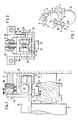
Figur 1 ein erfindungsgemäßes Farbwerk in einer schematischen DarstellungFigur 2 die Lagerung des Stempels in einer teilweise aufgebrochenen Seitenansicht und- Figur 3 einen Schnitt durch die Anordnung gemäß Fig. 2 entlang der Linie III.
- Figure 1 shows an inventive inking unit in a schematic representation
- Figure 2 shows the storage of the stamp in a partially broken side view
- 3 shows a section through the arrangement of FIG. 2 along the line III.
Das in Fig. 1 dargestellte Farbwerk umfaßt einen Farbkasten 1 mit einer Farbkastenwalze 2 und einem Farbmesser 3. Mit der Farbkastenwalze 3 wirkt eine Heberwalze 4 zusammen, die die Farbe an eine Reibwalze 5 weiterleitet. Das Farbwerk weist weiterhin eine Reihe von Übertragungswalzen 6, Reibwalzen 7 und Auftragwalzen 8, 9 auf. Die Anordnung der Walzen des Farbwerks ist für die Erfindung ohne Bedeutung, beispielsweise könnte auch ein anders aufgebautes Heberfarbwerk oder ein Filmfarbwerk erfindungsgemäß ausgestattet werden.The inking unit shown in FIG. 1 comprises an
Die Auftragwalzen 8, 9 übergeben die Farbe an einen in Richtung des Pfeiles a umlaufenden Plattenzylinder 10. An die Auftragwalze 9, die als letzte der Auftragwalzen 8, 9 dem Plattenzylinder Farbe zuführt, ist tangential in Richtung des Pfeiles b ein Stempel 11 anstellbar. Der Stempel 11 erstreckt sich über die gesamte Länge der Auftragwalze 9 und weist einen T-förmigen Querschnitt mit einer der Auftragwalze 9 zugewandten ebenen Anlagefläche 12 auf.The
Zur Halterung des Stempels 11 ist an dessen beiden Enden jeweils an einer Seitenwand 13, in der die Walzen des Farbwerks gelagert sind, ein Träger 14 befestigt. Zwischen zwei Seitenteilen 15 des Trägers 14 ist radial zur Auftragwalze 9 bewegbar ein Halter 16 gelagert. Am Halter 16 stützt sich das eine Ende einer Andruckfeder 17 ab, deren anderes Ende an einem Widerlager 18 anliegt. Das Widerlager 18 ist in ein durchgehendes Gewinde des Trägers 14 eingeschraubt. Durch weiteres Herein- oder Herausschrauben des Widerlagers 18 kann die von der Andruckfeder 17 auf den Halter 16 ausgeübte Kraft verändert werden.To hold the
Der Halter 16 weist zwei Seitenteile 19 auf. An jedem der beiden Seitenteile 19 ist eine Rolle 20 gelagert. Die beiden Rollen 20 liegen somit unter der Wirkung der Andruckfeder 17 am Stempel 11 an und drücken diesen gegen die Auftragwalze 9. Der Halter 16 trägt zwei weitere gestrichelt angedeute Rollen 21, die beiderseits am T-förmigen Mittelstück des Halters 11 anliegen und damit dessen seitliche Verschiebung verhindern. Letztlich ist an der Unterseite des Stempels 11 eine weitere Rolle 22 gelagert, die in eine Kurven-Nut-Führung 23 eines fest mit der Auftragwalze 9 verbundenen Flansches 24 eingreift. Am Halter 14 sind weiterhin ein Bodenteil 25, der ein Herausfallen des des Stempels 11 aus dem Halter 15 verhindert, und eine Frontplatte 26 befestigt, die den Halter 16 gegen Verschiebungen parallel zur Achse der Auftragwalze 9 sichert.The
Bildet sich im Betrieb der Druckmaschine ein Farbrelief auf der Auftragwalze 9 aus, so wird dieses durch die ebene Anlagefläche 12 des Stempels 11, der unter einstellbarem Druck gegen die Auftragwalze 9 geführt ist und changiert, zu einer Farbschicht gleichmässiger Dicke verrieben. Der Andruck des Stempels 11 wird dabei so eingestellt, daß der Stempel keine Farbe von der Auftragwalze 9 abquetscht. Damit wird dem Plattenzylinder 10 eine Farbschicht gleichmäßiger Dicke zugeführt.If a color relief is formed on the
Da beim dargestellten Ausführungsbeispiel die Auftragwalze 9 dem Plattenzylinder 10 die meiste Farbe zuführt, reicht es, den Stempel dieser Walze zuzuordnen. Grundsätzlich besteht jedoch die Möglichkeit, einen Stempel 11 auch noch weiteren Auftragwalzen zuzuordnen.Since in the illustrated embodiment the
Bei der Rotation der Farbauftragwalze 9 sorgt die Kurven-Nut-Führung 23 zusammen mit der Rolle 22 für eine parallel zur Achse der Auftragwalze 9 verlaufende Hin- und Herbewegung des Stempels 11. Dies ist jedoch nicht zwingend notwendig, da in manchen Fällen auch allein der Andruck des Stempels 11 gegen eine Auftragwalze 9 eine ausreichend gleichmäßige Farbschicht auf dieser Walze erzeugen kann.When the inking
Da der Stempel 11 von der Farbauftragwalze 9 keine Farbe abnimmt, kann über die Taktzeiten der Heberwalze 4 bzw. bei Filmfarbwerken das Farbmesser 3 und die Farbkastenwalze 2 eine sehr einfache und genaue Einstellung der vom Plattenzylinder 10 benötigten Farbmenge erfolgen.Since the
Claims (7)
dadurch gekennzeichnet,
daß tangential an mindestens eine Auftragwalze (9) ein über deren gesamte Länge durchlaufender Stempel (11) mit einer ebenen Anlagefläche (12) andrückbar ist.1. inking unit for rotary flat printing machines with an ink fountain roller, several transfer and friction rollers and at least one application roller as well as a device for uniformizing the color relief on the application roller,
characterized,
that a stamp (11) with a flat contact surface (12) can be pressed tangentially onto at least one applicator roller (9) over its entire length.
dadurch gekennzeichnet,
daß der Stempel (11) an die letzte dem Plattenzylinder (10) Farbe zuführende Auftragwalze (9) anstellbar ist.2. inking unit according to claim 1,
characterized,
that the stamp (11) on the last of the plate cylinder (10) ink supply roller (9) is adjustable.
dadurch gekennzeichnet,
daß der Stempel (11) unter der Wirkung von Andruckfedern (17) an der Auftragwalze (9) anliegt.3. inking unit according to claim 1 or 2,
characterized,
that the stamp (11) bears against the application roller (9) under the action of pressure springs (17).
dadurch gekennzeichnet,
daß der Stempel (11) in Achsrichtung der Auftragwalze (9) taktend hin- und hergehend angetrieben ist.4. Inking unit according to one of the preceding claims,
characterized,
that the stamp (11) in the axial direction of the applicator roller (9) is driven clockwise back and forth.
dadurch gekennzeichnet,
daß der Stempel (11) an beiden Enden parallel zur Achse der Auftragwalze (9) beweglich in je einem Halter (16) geführt und jeder Halter (16) in einem festen Träger (14) senkrecht zur Achse der Auftragwalze (9) beweglich gelagert ist und daß zwischen dem Halter (16) und dem Träger (14) eine Andruckfeder (17) angeordnet ist.5. Inking unit according to one of the preceding claims,
characterized,
that the stamp (11) at both ends parallel to the axis of the applicator roller (9) movably guided in a holder (16) and each holder (16) is movably mounted in a fixed support (14) perpendicular to the axis of the applicator roller (9) and that a pressure spring (17) is arranged between the holder (16) and the carrier (14).
dadurch gekennzeichnet,
daß der Stempel (11) eine Rolle (22) trägt, die in eine fest mit der der Auftragwalze (9) verbundene Kurven-Nut-Führung (23) eingreift.7. inking unit according to claim 4,
characterized,
that the stamp (11) carries a roller (22) which engages in a fixed with the applicator roller (9) curved groove guide (23).
Applications Claiming Priority (2)
| Application Number | Priority Date | Filing Date | Title |
|---|---|---|---|
| DE19863613877 DE3613877A1 (en) | 1986-04-24 | 1986-04-24 | INK FOR A ROTATIONAL FLAT PRINTING MACHINE |
| DE3613877 | 1986-04-24 |
Publications (2)
| Publication Number | Publication Date |
|---|---|
| EP0242648A2 true EP0242648A2 (en) | 1987-10-28 |
| EP0242648A3 EP0242648A3 (en) | 1989-04-26 |
Family
ID=6299439
Family Applications (1)
| Application Number | Title | Priority Date | Filing Date |
|---|---|---|---|
| EP87104792A Withdrawn EP0242648A3 (en) | 1986-04-24 | 1987-04-01 | Inking unit for a planographic rotary printing machine |
Country Status (4)
| Country | Link |
|---|---|
| US (1) | US4753166A (en) |
| EP (1) | EP0242648A3 (en) |
| JP (1) | JPS62257850A (en) |
| DE (1) | DE3613877A1 (en) |
Families Citing this family (5)
| Publication number | Priority date | Publication date | Assignee | Title |
|---|---|---|---|---|
| US4796530A (en) * | 1987-06-01 | 1989-01-10 | Pathfinder Graphic Associates Inc. | Oscillating roll for printing presses |
| US5178678A (en) * | 1989-06-13 | 1993-01-12 | Dahlgren International, Inc. | Retractable coater assembly including a coating blanket cylinder |
| US4934305A (en) * | 1989-06-13 | 1990-06-19 | Dahlgren International, Inc. | Retractable coater assembly including a coating blanket cylinder |
| US5630363A (en) | 1995-08-14 | 1997-05-20 | Williamson Printing Corporation | Combined lithographic/flexographic printing apparatus and process |
| CN100575082C (en) * | 2004-08-04 | 2009-12-30 | 海德堡印刷机械股份公司 | Printing machine |
Family Cites Families (21)
| Publication number | Priority date | Publication date | Assignee | Title |
|---|---|---|---|---|
| DE238850C (en) * | ||||
| DE346247C (en) * | 1920-04-23 | 1921-12-28 | Albert & Cie A G | Inking unit for printing machines |
| GB256703A (en) * | 1925-05-14 | 1926-08-16 | Isaac Charles Squier | Improvements in inking mechanism for printing presses |
| US1942490A (en) * | 1932-09-23 | 1934-01-09 | Hugh T Quigley | Ink double-rolling control |
| US2076203A (en) * | 1934-12-21 | 1937-04-06 | Mailander Willy | Photogravure plate printing press |
| US2318504A (en) * | 1938-12-09 | 1943-05-04 | Frederick W Lodding | Doctor operating mechanism for rolls and cylinders |
| DE2052806A1 (en) * | 1970-10-28 | 1972-05-04 | Koenig & Bauer Schnellpressfab | Inking unit for printing machines |
| DE2243248A1 (en) * | 1972-09-02 | 1974-03-21 | Roland Offsetmaschf | INK WORK ON SHEET MACHINES, IN PARTICULAR OFFSET MACHINES |
| DE2509837A1 (en) * | 1974-04-24 | 1975-11-06 | Xerox Corp | PROCESS FOR INKING A SURFACE |
| CH583097A5 (en) * | 1975-05-05 | 1976-12-31 | Wifag Maschf | |
| US4126091A (en) * | 1976-12-21 | 1978-11-21 | Cohen Abraham N | Fountain blade and apparatus for calibrating the same |
| DE2658362C3 (en) * | 1976-12-23 | 1984-08-09 | Hinterkopf, Kurt G., Dipl.-Ing. (FH), 7332 Eislingen | Inking unit for a printing machine, especially for printing tubes, sleeves and the like. |
| US4151797A (en) * | 1977-05-04 | 1979-05-01 | Mid America Tag And Label Company, Inc. | Doctor blade apparatus |
| US4354449A (en) * | 1978-07-03 | 1982-10-19 | The Black Clawson Company | Two sided coater |
| DE2902230A1 (en) * | 1979-01-20 | 1980-07-24 | Maschf Augsburg Nuernberg Ag | INK |
| DE3028406C2 (en) * | 1980-07-26 | 1983-09-15 | Heidelberger Druckmaschinen Ag, 6900 Heidelberg | Device for the axial back and forth movement of distribution rollers in the inking unit of printing machines |
| DD154530A5 (en) * | 1980-11-05 | 1982-03-31 | Dahlgren Mfg Co | METHOD AND DEVICE FOR DOSING PRINTING COLOR |
| US4398463A (en) * | 1981-08-19 | 1983-08-16 | Motter Printing Press Co. | Non-repeat doctor blade drive |
| DE3225378A1 (en) * | 1982-07-07 | 1984-01-12 | Koenig & Bauer AG, 8700 Würzburg | INK |
| DE3324893C1 (en) * | 1983-07-09 | 1985-03-14 | Heidelberger Druckmaschinen Ag, 6900 Heidelberg | Device for dosing the color in offset printing machines |
| DE3344778C1 (en) * | 1983-12-10 | 1985-04-11 | M.A.N.- Roland Druckmaschinen AG, 6050 Offenbach | Ink metering device for the inking unit of a printing machine |
-
1986
- 1986-04-24 DE DE19863613877 patent/DE3613877A1/en active Granted
-
1987
- 1987-03-27 US US07/031,699 patent/US4753166A/en not_active Expired - Fee Related
- 1987-04-01 EP EP87104792A patent/EP0242648A3/en not_active Withdrawn
- 1987-04-16 JP JP62092141A patent/JPS62257850A/en active Pending
Also Published As
| Publication number | Publication date |
|---|---|
| DE3613877C2 (en) | 1988-09-01 |
| DE3613877A1 (en) | 1987-10-29 |
| US4753166A (en) | 1988-06-28 |
| JPS62257850A (en) | 1987-11-10 |
| EP0242648A3 (en) | 1989-04-26 |
Similar Documents
| Publication | Publication Date | Title |
|---|---|---|
| CH620864A5 (en) | ||
| EP0453910B1 (en) | Ink rail device | |
| CH672096A5 (en) | ||
| DE1923475B2 (en) | DEVICE FOR THE ON AND OFF OF THE MOISTURIZING ROLLERS OF AN OFFSET ROTARY PRINTING MACHINE WITH ONE OF A DIP ROLLER, A SIZING ROLLER, AN INTERMEDIATE ROLLER AND ONE OR MORE FORM ROLLERS, WHICH HAS BEEN RESTORED ON THE MOISTURIZING ROLLER | |
| EP0751256A2 (en) | Doctoring assembly | |
| DE4213660C2 (en) | Short inking unit for a web-fed rotary printing press | |
| DE1243695B (en) | Inking unit for printing machines | |
| DE102012201378A1 (en) | Device for setting squeegee to outer surface of rotatable roller, has control unit which controls engagement force against outer surface of roller and/or position of squeegees, so that squeegees comprise value exhibited before change | |
| EP0512267B1 (en) | Laminator | |
| EP0242648A2 (en) | Inking unit for a planographic rotary printing machine | |
| DE4400563C2 (en) | Roller in an inking unit or dampening unit of a rotary printing press | |
| EP0210671B1 (en) | Damping device for a printing press | |
| DE4004963A1 (en) | DEVICE FOR APPLYING ADHESIVE TO CUTTING PACKAGING MATERIAL | |
| DE4213663C2 (en) | Doctor bar for a short inking unit of a web-fed rotary printing press | |
| CH652347A5 (en) | DEVICE FOR APPLYING A LIQUID OR SEMI-FLUID MEDIUM ON THE PRINT PLATE OF A PRINTING MACHINE, IN PARTICULAR OFFSET PRINTING MACHINE. | |
| DE3302872A1 (en) | SHORT COLOR PLANT | |
| EP0845354B1 (en) | Ink fountain for rotary presses | |
| EP0741018A2 (en) | Device for bearing an applicator roll | |
| DE3630491A1 (en) | Device for the selective axial movement of ink applicator rollers | |
| CH687185A5 (en) | Blade beam. | |
| DD148607A1 (en) | COLOR FACTORY | |
| DE3336919C2 (en) | Device for zone-wise adjustment of an ink knife | |
| DE1915280B2 (en) | Device for adjusting the applicator roller of an inking unit of a printing machine | |
| DE4340079C2 (en) | Offset printing machine with a numbering unit | |
| EP0984860A1 (en) | Cylinder with a rubber liner and device for applying said liner |
Legal Events
| Date | Code | Title | Description |
|---|---|---|---|
| PUAI | Public reference made under article 153(3) epc to a published international application that has entered the european phase |
Free format text: ORIGINAL CODE: 0009012 |
|
| AK | Designated contracting states |
Kind code of ref document: A2 Designated state(s): CH DE FR IT LI SE |
|
| PUAL | Search report despatched |
Free format text: ORIGINAL CODE: 0009013 |
|
| AK | Designated contracting states |
Kind code of ref document: A3 Designated state(s): CH DE FR IT LI SE |
|
| 17P | Request for examination filed |
Effective date: 19890310 |
|
| STAA | Information on the status of an ep patent application or granted ep patent |
Free format text: STATUS: THE APPLICATION IS DEEMED TO BE WITHDRAWN |
|
| 18D | Application deemed to be withdrawn |
Effective date: 19901003 |
|
| RIN1 | Information on inventor provided before grant (corrected) |
Inventor name: FISCHER, HERMANN |