EP0242500B1 - Dispositif pour l'accélération de projectiles par un plasma chauffé électriquement - Google Patents
Dispositif pour l'accélération de projectiles par un plasma chauffé électriquement Download PDFInfo
- Publication number
- EP0242500B1 EP0242500B1 EP87100186A EP87100186A EP0242500B1 EP 0242500 B1 EP0242500 B1 EP 0242500B1 EP 87100186 A EP87100186 A EP 87100186A EP 87100186 A EP87100186 A EP 87100186A EP 0242500 B1 EP0242500 B1 EP 0242500B1
- Authority
- EP
- European Patent Office
- Prior art keywords
- projectile
- electrode
- plasma
- electrodes
- fact
- Prior art date
- Legal status (The legal status is an assumption and is not a legal conclusion. Google has not performed a legal analysis and makes no representation as to the accuracy of the status listed.)
- Expired - Lifetime
Links
- 239000000126 substance Substances 0.000 claims description 6
- 239000004698 Polyethylene Substances 0.000 claims description 3
- -1 polyethylene Polymers 0.000 claims description 3
- 229920000573 polyethylene Polymers 0.000 claims description 3
- 238000003475 lamination Methods 0.000 claims 1
- 238000004519 manufacturing process Methods 0.000 claims 1
- 210000002381 plasma Anatomy 0.000 description 27
- 239000000463 material Substances 0.000 description 9
- 239000004020 conductor Substances 0.000 description 8
- 239000007789 gas Substances 0.000 description 6
- 241000446313 Lamella Species 0.000 description 5
- 230000001133 acceleration Effects 0.000 description 5
- 238000010586 diagram Methods 0.000 description 4
- 238000010438 heat treatment Methods 0.000 description 4
- 230000008020 evaporation Effects 0.000 description 3
- 238000001704 evaporation Methods 0.000 description 3
- 238000000034 method Methods 0.000 description 3
- 238000007789 sealing Methods 0.000 description 3
- 238000004795 WEFT sequence Methods 0.000 description 1
- 238000002679 ablation Methods 0.000 description 1
- XAGFODPZIPBFFR-UHFFFAOYSA-N aluminium Chemical compound [Al] XAGFODPZIPBFFR-UHFFFAOYSA-N 0.000 description 1
- 229910052782 aluminium Inorganic materials 0.000 description 1
- 238000002485 combustion reaction Methods 0.000 description 1
- 230000003247 decreasing effect Effects 0.000 description 1
- 230000000694 effects Effects 0.000 description 1
- 238000010891 electric arc Methods 0.000 description 1
- 239000000446 fuel Substances 0.000 description 1
- 230000004927 fusion Effects 0.000 description 1
- 230000000977 initiatory effect Effects 0.000 description 1
- 239000011810 insulating material Substances 0.000 description 1
- 239000007788 liquid Substances 0.000 description 1
- 239000004033 plastic Substances 0.000 description 1
- 229920003023 plastic Polymers 0.000 description 1
- 239000004417 polycarbonate Substances 0.000 description 1
- 229920000515 polycarbonate Polymers 0.000 description 1
- 238000012827 research and development Methods 0.000 description 1
- 229920002379 silicone rubber Polymers 0.000 description 1
- 239000004945 silicone rubber Substances 0.000 description 1
Images


Classifications
-
- F—MECHANICAL ENGINEERING; LIGHTING; HEATING; WEAPONS; BLASTING
- F41—WEAPONS
- F41B—WEAPONS FOR PROJECTING MISSILES WITHOUT USE OF EXPLOSIVE OR COMBUSTIBLE PROPELLANT CHARGE; WEAPONS NOT OTHERWISE PROVIDED FOR
- F41B6/00—Electromagnetic launchers ; Plasma-actuated launchers
Definitions
- the present invention relates to a device for accelerating projectiles located in a tube closed on one side by an electrically heated plasma with the features of the preamble of claim 1.
- the present invention was therefore based on the object of further developing a device of the type mentioned at the outset in such a way that the corresponding tube parts are subject to only slight wear, even with a high weft sequence.
- the invention is therefore essentially based on the fact that the spread of the plasma is no longer initiated by parts of the accelerator itself, as in the known devices, but rather that both the initiation of the gas discharge and the subsequent heating processes in easily replaceable separate units in which the projectile is also located. Therefore, not only the projectiles but rather the entire cartridge are preferably fed to the tube.
- a known acceleration device is shown again, such as that in the report by Goldstein et. al. is described in more detail.
- Fig. 1 denotes a tube which is closed on one side and on the tube bottom of which the closure is located a first electrode 2 is arranged.
- a second electrode (ring electrode) 3 is connected to the first electrode 2 via a voltage source 4 and a switch.
- the two electrodes 2 and 3 define a plasma chamber designated 6 in the tube 1, which is initially closed in the area of the ring electrode 3 by a projectile 7 to be accelerated.
- this device has the disadvantage that the part of the tube forming the plasma space is subject to extremely high wear due to the material evaporation and heating processes.
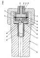
- FIG. 2 The cartridge 8 shown in FIG. 2 and then its function in connection with a gun (FIG. 3) will be described in more detail below.
- the cartridge 8 essentially consists of the projectile 80, a sleeve 81 surrounding the projectile, a second electrode 82 designed as a contact ring and a first electrode 83 designed as a contact piece.
- the first electrode 83 and the second electrode 82 are separated by an insulating piece 84.
- the second electrode 82 has a contact plate ring 85 on its front side and a contact plate ring 86 on its rear side.
- the first electrode 83 has a contact lamella 87 on its side facing away from the projectile 80.
- a splat-shaped discharge space 88 is located between the projectile 80 and the first electrode 83.
- the sleeve 81 can preferably consist of a combustible, light-gas material, for example polyethylene, and the insulating body 84 can be made of polycarbonate.
- light-gassing materials are substances that break down into molecules (gases) with a low molecular weight (molecular weight ⁇ 30) under the effect of the arc discharge.
- aluminum was used as the material for the electrodes 82 and 83.
- Fig. 3 shows how the cartridge 8 is arranged in a plasma gun.
- Lichen parts, such as the closure were only shown schematically.
- a base piece 91 is screwed onto the tube 90, for example.
- Both an inner conductor 92 and an outer conductor 93, which is electrically separated from the inner conductor 92 by insulating means 94, are guided through an opening 95 of the base piece 91 into the sealing space of the tube 90, which is not specifically designated.
- the inner conductor 92 is then contacted in the sealing space via the contact lamella disk 87 with the first electrode 83.
- the outer conductor 93 is correspondingly connected to the ring electrode 82 via the contact lamella ring 86.
- the contacts 85, 86 and 87 of the cartridge are pressed firmly against the tube 90 and against the coaxial first electrode by the pressure of the base piece 91.
- An elastic silicone rubber seal 97 is arranged between the insulating means 94 and the insulating piece 84 for electrical sealing.
- a voltage is applied between the inner conductor 92 and the outer conductor 93.
- the acceleration process is then initiated by a gas discharge which forms between the first electrode 83 and the coaxial electrode 82 in the narrow gap 88 and which is indicated by 96 in FIG. 3.
- a gas discharge which forms between the first electrode 83 and the coaxial electrode 82 in the narrow gap 88 and which is indicated by 96 in FIG. 3.
- material is vaporized and predominantly in the base areas of the hot arc heated up.
- further material is evaporated by the close contact of the arc with the walls of the gap 88. The resulting pressure drives the projectile 80 towards the pipe end.
- a plasma forms behind the projectile 80 in the increasing combustion chamber.
- the plasma consists of a current-carrying stem in the axis of the accelerator and (if a sleeve 81 made of plastic is used) a current-carrying sleeve which is pressed against the sleeve 81 by the current forces that occur. Due to the close contact of the plasma shell with the sleeve 81, the latter is vaporized on the surface and thus further material is supplied to the plasma.
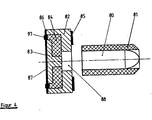
- FIG. 4 shows a further exemplary embodiment according to the invention.
- the same parts as in Fig. 2 have been given the same reference numerals.
- the projectile 80 with the sleeve 81 on the one hand and on the other hand the electrodes 82, 83 provided with the contact blades 85, 86, 87 with the insulating piece 84 are each combined to form a unit.
- Such a division into separate structural units makes it possible first to introduce the projectile 80 with the sleeve 81 and in a subsequent period of time the unit consisting of electrodes 82, 83 and insulating piece 84 into the gun barrel. Such a division and loading into two time periods is often necessary, especially for large-caliber weapons.
- FIG. 5 shows a simplified circuit diagram for operating the plasma cannon according to the invention.
- the schematically illustrated plasma cannon was designated by 10 and the simplified circuit diagram by 11. Only a projectile 100 was shown in the plasma gun 10 instead of a cartridge. 101 denotes the first electrode and 102 denotes the second electrode, which is connected to the tube.
- a drive for. B. a motor powered by a liquid fuel
- 111 denotes a DC generator.
- the voltage generated by the direct current generator is fed via switch 112 to a capacitance 113, which acts as a capacitive energy store.
- the capacitance 113 is connected on the one hand to the first electrode 101 via a switch 114 and on the other hand to the second electrode 102 via an inductance 116.
- the capacitance 113 can be short-circuited via a switch 115.
- the capacitive energy store 113 is charged to the voltage Uo.
- the gap-shaped space 88 can also be filled with a slightly gassing substance (e.g. polyethylene). Because the additional material evaporation of this substance increases the plasma pressure, so that the projectile leaves the tube 90 at a higher speed.
- a slightly gassing substance e.g. polyethylene
Landscapes
- Engineering & Computer Science (AREA)
- Physics & Mathematics (AREA)
- Electromagnetism (AREA)
- Plasma & Fusion (AREA)
- General Engineering & Computer Science (AREA)
- Plasma Technology (AREA)
- Generation Of Surge Voltage And Current (AREA)
- Magnetic Treatment Devices (AREA)
- Vending Machines For Individual Products (AREA)
- Buildings Adapted To Withstand Abnormal External Influences (AREA)
Claims (5)
Applications Claiming Priority (2)
| Application Number | Priority Date | Filing Date | Title |
|---|---|---|---|
| DE19863613259 DE3613259A1 (de) | 1986-04-19 | 1986-04-19 | Vorrichtung zur beschleunigung von projektilen durch ein elektrisch aufgeheiztes plasma |
| DE3613259 | 1986-04-19 |
Publications (2)
| Publication Number | Publication Date |
|---|---|
| EP0242500A1 EP0242500A1 (fr) | 1987-10-28 |
| EP0242500B1 true EP0242500B1 (fr) | 1990-04-04 |
Family
ID=6299057
Family Applications (1)
| Application Number | Title | Priority Date | Filing Date |
|---|---|---|---|
| EP87100186A Expired - Lifetime EP0242500B1 (fr) | 1986-04-19 | 1987-01-09 | Dispositif pour l'accélération de projectiles par un plasma chauffé électriquement |
Country Status (5)
| Country | Link |
|---|---|
| EP (1) | EP0242500B1 (fr) |
| JP (1) | JPS62248999A (fr) |
| DE (2) | DE3613259A1 (fr) |
| ES (1) | ES2013729B3 (fr) |
| NO (1) | NO870473L (fr) |
Families Citing this family (14)
| Publication number | Priority date | Publication date | Assignee | Title |
|---|---|---|---|---|
| JPH067040B2 (ja) * | 1988-03-29 | 1994-01-26 | 防衛庁技術研究本部長 | 電磁加速装置 |
| US5042359A (en) * | 1988-04-28 | 1991-08-27 | Rheinmetall Gmbh | Projectile accelerating device |
| DE3814332C2 (de) * | 1988-04-28 | 1997-05-15 | Rheinmetall Ind Ag | Vorrichtung zur Beschleunigung von Projektilen |
| DE3814330C2 (de) * | 1988-04-28 | 1997-05-15 | Rheinmetall Ind Ag | Elektrothermische Beschleunigungsvorrichtung |
| DE3814331A1 (de) * | 1988-04-28 | 1989-11-09 | Rheinmetall Gmbh | Vorrichtung zur beschleunigung von projektilen |
| DE3816300A1 (de) * | 1988-05-13 | 1989-11-23 | Tzn Forschung & Entwicklung | Kartusche fuer elektrothermische abschussvorrichtungen |
| DE3830902C1 (fr) * | 1988-09-10 | 1992-04-09 | Diehl Gmbh & Co, 8500 Nuernberg, De | |
| DE3910566A1 (de) * | 1989-04-01 | 1990-10-04 | Diehl Gmbh & Co | Vorrichtung zum beschleunigen eines projektils mittels eines plasmas |
| DE3921400C2 (de) * | 1989-06-29 | 1997-03-27 | Deutsch Franz Forsch Inst | Kanonenanordnung |
| DE3924056A1 (de) * | 1989-07-21 | 1991-01-24 | Diehl Gmbh & Co | Vorrichtung zur beschleunigung von projektilen durch ein elektrisch aufgeheiztes plasma |
| DE4028874A1 (de) * | 1990-09-12 | 1992-03-19 | Diehl Gmbh & Co | Elektrothermische kanone |
| DE4132657C2 (de) * | 1991-10-01 | 1996-02-08 | Tzn Forschung & Entwicklung | Elektrothermische Abschußvorrichtung und Kartusche zur Verwendung in derartigen Vorrichtungen |
| DE19617895C2 (de) * | 1996-05-04 | 1998-02-26 | Rheinmetall Ind Ag | Plasmainjektionsvorrichtung |
| CN113916050B (zh) * | 2021-10-19 | 2023-06-20 | 西南科技大学 | 一种电弧放电赋能气体驱动的二级轻气炮 |
Family Cites Families (4)
| Publication number | Priority date | Publication date | Assignee | Title |
|---|---|---|---|---|
| US3431816A (en) * | 1967-07-21 | 1969-03-11 | John R Dale | Mobile gas-operated electrically-actuated projectile firing system |
| US4170922A (en) * | 1977-09-16 | 1979-10-16 | The United States Of America As Represented By The Secretary Of The Navy | Ignitor |
| US4534263A (en) * | 1982-07-19 | 1985-08-13 | Westinghouse Electric Corp. | Electromagnetic launcher with high repetition rate switch |
| DE3321034A1 (de) * | 1983-06-10 | 1984-12-13 | Messerschmitt-Bölkow-Blohm GmbH, 8012 Ottobrunn | Elektromagnetische kanone |
-
1986
- 1986-04-19 DE DE19863613259 patent/DE3613259A1/de active Granted
-
1987
- 1987-01-09 ES ES87100186T patent/ES2013729B3/es not_active Expired - Lifetime
- 1987-01-09 EP EP87100186A patent/EP0242500B1/fr not_active Expired - Lifetime
- 1987-01-09 DE DE8787100186T patent/DE3762165D1/de not_active Expired - Fee Related
- 1987-02-02 JP JP62020605A patent/JPS62248999A/ja active Pending
- 1987-02-06 NO NO870473A patent/NO870473L/no unknown
Also Published As
| Publication number | Publication date |
|---|---|
| NO870473D0 (no) | 1987-02-06 |
| DE3613259C2 (fr) | 1989-12-21 |
| ES2013729B3 (es) | 1990-06-01 |
| EP0242500A1 (fr) | 1987-10-28 |
| DE3613259A1 (de) | 1987-10-29 |
| JPS62248999A (ja) | 1987-10-29 |
| DE3762165D1 (de) | 1990-05-10 |
| NO870473L (no) | 1987-10-20 |
Similar Documents
| Publication | Publication Date | Title |
|---|---|---|
| EP0242500B1 (fr) | Dispositif pour l'accélération de projectiles par un plasma chauffé électriquement | |
| EP1348929B1 (fr) | Cartouche de munition ayant une charge propulsive à allumage électrique | |
| DE68909659T2 (de) | Plasma-Waffe mit einem Verbrennungsverstärker. | |
| DE3413728C3 (fr) | ||
| DE3814331C2 (fr) | ||
| EP0242501B1 (fr) | Dispositif pour l'accélération de projectiles par un plasma chauffé électriquement | |
| DE3814330C2 (de) | Elektrothermische Beschleunigungsvorrichtung | |
| DE1514402A1 (de) | Beruehrungssichere Ionisierungs-Luftduese | |
| DE4410325C2 (de) | Waffenrohr mit einer erosionsmindernden Einlage und Verwendung des Waffenrohres in elektrischen Kanonen | |
| DE19617895C2 (de) | Plasmainjektionsvorrichtung | |
| DE4132657C2 (de) | Elektrothermische Abschußvorrichtung und Kartusche zur Verwendung in derartigen Vorrichtungen | |
| DE3615585C1 (de) | Projektil zum Verschiessen aus einer elektromagnetischen Geschossbeschleunigungsvorrichtung | |
| DE3012497A1 (de) | Verfahren zum herstellen einer zuendelektrode | |
| DE19757443C2 (de) | Plasmabrennervorrichtung für elektrothermische und elektrothermisch-chemische Kanonensysteme | |
| DE2209388A1 (de) | Verfahren zur unterbrechung eines lichtbogens und anordnung zur durchfuehrung des verfahrens | |
| EP0899356B1 (fr) | Méthode et dispositif pour la formation d'un revêtenment sur la paroi interne d'un tube métallique | |
| DE3814332C2 (de) | Vorrichtung zur Beschleunigung von Projektilen | |
| DE4003320C2 (de) | Geschoß für elektrothermische Beschleunigungsvorrichtungen | |
| EP1148313B1 (fr) | Dispositif d'allumage électrothermique pour cartouche de munition et son procédé de fabrication | |
| DE3910566C2 (fr) | ||
| DE3716078A1 (de) | Lauf zur beschleunigung von geschossen | |
| DE4039089A1 (de) | Vorrichtung zum beschleunigen eines projektils mittels eines plasmas | |
| DE4337964C2 (de) | Elektrischer Hybridbeschleuniger für eine Spezialmuntion | |
| DE1777441A1 (de) | Elektrodenanordnung fuer eine vorrichtung zum plastischen verformen eines werkstueckes | |
| EP0080690B1 (fr) | Procédé pour éteindre l'arc dans des disjoncteurs haute tension de puissance élevée |
Legal Events
| Date | Code | Title | Description |
|---|---|---|---|
| PUAI | Public reference made under article 153(3) epc to a published international application that has entered the european phase |
Free format text: ORIGINAL CODE: 0009012 |
|
| 17P | Request for examination filed |
Effective date: 19870424 |
|
| AK | Designated contracting states |
Kind code of ref document: A1 Designated state(s): CH DE ES FR GB IT LI NL SE |
|
| 17Q | First examination report despatched |
Effective date: 19880705 |
|
| ITF | It: translation for a ep patent filed | ||
| GRAA | (expected) grant |
Free format text: ORIGINAL CODE: 0009210 |
|
| AK | Designated contracting states |
Kind code of ref document: B1 Designated state(s): CH DE ES FR GB IT LI NL SE |
|
| GBT | Gb: translation of ep patent filed (gb section 77(6)(a)/1977) | ||
| REF | Corresponds to: |
Ref document number: 3762165 Country of ref document: DE Date of ref document: 19900510 |
|
| ET | Fr: translation filed | ||
| PG25 | Lapsed in a contracting state [announced via postgrant information from national office to epo] |
Ref country code: SE Effective date: 19910110 Ref country code: ES Free format text: LAPSE BECAUSE OF NON-PAYMENT OF DUE FEES Effective date: 19910110 |
|
| PLBE | No opposition filed within time limit |
Free format text: ORIGINAL CODE: 0009261 |
|
| STAA | Information on the status of an ep patent application or granted ep patent |
Free format text: STATUS: NO OPPOSITION FILED WITHIN TIME LIMIT |
|
| PG25 | Lapsed in a contracting state [announced via postgrant information from national office to epo] |
Ref country code: LI Effective date: 19910131 Ref country code: CH Effective date: 19910131 |
|
| 26N | No opposition filed | ||
| PG25 | Lapsed in a contracting state [announced via postgrant information from national office to epo] |
Ref country code: NL Effective date: 19910801 |
|
| NLV4 | Nl: lapsed or anulled due to non-payment of the annual fee | ||
| REG | Reference to a national code |
Ref country code: CH Ref legal event code: PL |
|
| EUG | Se: european patent has lapsed |
Ref document number: 87100186.3 Effective date: 19910910 |
|
| PGFP | Annual fee paid to national office [announced via postgrant information from national office to epo] |
Ref country code: GB Payment date: 19971211 Year of fee payment: 12 |
|
| PGFP | Annual fee paid to national office [announced via postgrant information from national office to epo] |
Ref country code: FR Payment date: 19971231 Year of fee payment: 12 |
|
| PGFP | Annual fee paid to national office [announced via postgrant information from national office to epo] |
Ref country code: DE Payment date: 19980107 Year of fee payment: 12 |
|
| PG25 | Lapsed in a contracting state [announced via postgrant information from national office to epo] |
Ref country code: GB Free format text: LAPSE BECAUSE OF NON-PAYMENT OF DUE FEES Effective date: 19990109 |
|
| REG | Reference to a national code |
Ref country code: ES Ref legal event code: FD2A Effective date: 19990201 |
|
| GBPC | Gb: european patent ceased through non-payment of renewal fee |
Effective date: 19990109 |
|
| PG25 | Lapsed in a contracting state [announced via postgrant information from national office to epo] |
Ref country code: FR Free format text: LAPSE BECAUSE OF NON-PAYMENT OF DUE FEES Effective date: 19990930 |
|
| PG25 | Lapsed in a contracting state [announced via postgrant information from national office to epo] |
Ref country code: DE Free format text: LAPSE BECAUSE OF NON-PAYMENT OF DUE FEES Effective date: 19991103 |
|
| REG | Reference to a national code |
Ref country code: FR Ref legal event code: ST |
|
| PG25 | Lapsed in a contracting state [announced via postgrant information from national office to epo] |
Ref country code: IT Free format text: LAPSE BECAUSE OF NON-PAYMENT OF DUE FEES;WARNING: LAPSES OF ITALIAN PATENTS WITH EFFECTIVE DATE BEFORE 2007 MAY HAVE OCCURRED AT ANY TIME BEFORE 2007. THE CORRECT EFFECTIVE DATE MAY BE DIFFERENT FROM THE ONE RECORDED. Effective date: 20050109 |