EP0241969B1 - Fauteuil pour véhicule, notamment automobile - Google Patents
Fauteuil pour véhicule, notamment automobile Download PDFInfo
- Publication number
- EP0241969B1 EP0241969B1 EP87200555A EP87200555A EP0241969B1 EP 0241969 B1 EP0241969 B1 EP 0241969B1 EP 87200555 A EP87200555 A EP 87200555A EP 87200555 A EP87200555 A EP 87200555A EP 0241969 B1 EP0241969 B1 EP 0241969B1
- Authority
- EP
- European Patent Office
- Prior art keywords
- seat
- seatback
- vehicle
- backrest
- relation
- Prior art date
- Legal status (The legal status is an assumption and is not a legal conclusion. Google has not performed a legal analysis and makes no representation as to the accuracy of the status listed.)
- Expired - Lifetime
Links
- 230000001174 ascending effect Effects 0.000 claims description 5
- 230000005540 biological transmission Effects 0.000 claims 1
- 239000000725 suspension Substances 0.000 description 3
- 238000010276 construction Methods 0.000 description 2
- 230000009931 harmful effect Effects 0.000 description 2
- 230000010355 oscillation Effects 0.000 description 2
- 208000008035 Back Pain Diseases 0.000 description 1
- 208000002193 Pain Diseases 0.000 description 1
- 239000006096 absorbing agent Substances 0.000 description 1
- 230000009286 beneficial effect Effects 0.000 description 1
- 239000000470 constituent Substances 0.000 description 1
- 230000000694 effects Effects 0.000 description 1
- 230000002349 favourable effect Effects 0.000 description 1
- 239000006260 foam Substances 0.000 description 1
- 238000004519 manufacturing process Methods 0.000 description 1
- 239000000463 material Substances 0.000 description 1
- 238000005259 measurement Methods 0.000 description 1
- 239000002184 metal Substances 0.000 description 1
- 230000003534 oscillatory effect Effects 0.000 description 1
- 230000035939 shock Effects 0.000 description 1
- 238000005303 weighing Methods 0.000 description 1
Images
Classifications
-
- B—PERFORMING OPERATIONS; TRANSPORTING
- B60—VEHICLES IN GENERAL
- B60N—SEATS SPECIALLY ADAPTED FOR VEHICLES; VEHICLE PASSENGER ACCOMMODATION NOT OTHERWISE PROVIDED FOR
- B60N2/00—Seats specially adapted for vehicles; Arrangement or mounting of seats in vehicles
- B60N2/64—Back-rests or cushions
- B60N2/643—Back-rests or cushions shape of the back-rests
-
- B—PERFORMING OPERATIONS; TRANSPORTING
- B60—VEHICLES IN GENERAL
- B60N—SEATS SPECIALLY ADAPTED FOR VEHICLES; VEHICLE PASSENGER ACCOMMODATION NOT OTHERWISE PROVIDED FOR
- B60N2/00—Seats specially adapted for vehicles; Arrangement or mounting of seats in vehicles
- B60N2/02—Seats specially adapted for vehicles; Arrangement or mounting of seats in vehicles the seat or part thereof being movable, e.g. adjustable
- B60N2/028—Elastically mounted back-rests
-
- B—PERFORMING OPERATIONS; TRANSPORTING
- B60—VEHICLES IN GENERAL
- B60N—SEATS SPECIALLY ADAPTED FOR VEHICLES; VEHICLE PASSENGER ACCOMMODATION NOT OTHERWISE PROVIDED FOR
- B60N2/00—Seats specially adapted for vehicles; Arrangement or mounting of seats in vehicles
- B60N2/02—Seats specially adapted for vehicles; Arrangement or mounting of seats in vehicles the seat or part thereof being movable, e.g. adjustable
- B60N2/22—Seats specially adapted for vehicles; Arrangement or mounting of seats in vehicles the seat or part thereof being movable, e.g. adjustable the back-rest being adjustable
- B60N2/2222—Seats specially adapted for vehicles; Arrangement or mounting of seats in vehicles the seat or part thereof being movable, e.g. adjustable the back-rest being adjustable the back-rest having two or more parts
-
- B—PERFORMING OPERATIONS; TRANSPORTING
- B60—VEHICLES IN GENERAL
- B60N—SEATS SPECIALLY ADAPTED FOR VEHICLES; VEHICLE PASSENGER ACCOMMODATION NOT OTHERWISE PROVIDED FOR
- B60N2/00—Seats specially adapted for vehicles; Arrangement or mounting of seats in vehicles
- B60N2/50—Seat suspension devices
- B60N2/509—Seat guided by slides or the like
-
- B—PERFORMING OPERATIONS; TRANSPORTING
- B60—VEHICLES IN GENERAL
- B60N—SEATS SPECIALLY ADAPTED FOR VEHICLES; VEHICLE PASSENGER ACCOMMODATION NOT OTHERWISE PROVIDED FOR
- B60N2/00—Seats specially adapted for vehicles; Arrangement or mounting of seats in vehicles
- B60N2/02—Seats specially adapted for vehicles; Arrangement or mounting of seats in vehicles the seat or part thereof being movable, e.g. adjustable
- B60N2/22—Seats specially adapted for vehicles; Arrangement or mounting of seats in vehicles the seat or part thereof being movable, e.g. adjustable the back-rest being adjustable
- B60N2002/2204—Adjustable back-rest height or length
Definitions
- the present invention relates to an armchair for a vehicle, in particular a motor vehicle, as defined in the preamble of claim 1.
- a vehicle in particular a motor vehicle
- Such an armchair is known from BE-A-900 876.
- One of the essential aims of the present invention is to present an armchair of the aforementioned type making it possible to eliminate or at least attenuate in a very effective manner the pain in the back of the passenger of the vehicle, caused by the vertical oscillations of the armchair, induced by example by the unevenness of the road in the case of a motor vehicle.
- the natural frequencies of the loaded passenger seat and the movable part of the backrest are approximately equal, a phenomenon of resonance occurs, so that the oscillation of the movable part of the backrest can have a much greater amplitude than that of the passenger seat.
- One of the essential aims of the present invention is to propose an armchair of the aforementioned type of a very simple construction which makes it possible, without requiring special precautions, from the point of view of choice of materials and arrangement of the constituent parts of the backrest, to delete or to less significantly reduce the passenger's back pain.
- the part of the backrest, against which the back rests is arranged so as to rest on the elastic members, which comprise at least one helical spring threaded on a guide rod extending along the direction of the above-mentioned upward and downward movement, this rod being fixed relative to a part of the backrest and sliding relative to the other part in said direction.
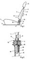
- Figure 1 is a schematic side view of an armchair according to this particular embodiment of the invention.
- Figure 2 is, on a larger scale, a longitudinal section of an essential part of the chair according to this embodiment particular.
- the essential object of the present invention is to present a vehicle chair in which the relative importance of the inertia effect has been modified compared to that of other factors.
- the vibrations to which the vertebral column of a passenger of a vehicle, in particular an automobile, is subjected, are due to the vibrations of the floor on which the wheelchair in which the passenger is seated is fixed.
- the main quality which the whole of the armchair must have is that the construction must be such that the vibrations of the floor of the vehicle, having a frequency greater than 10 Hz, do not reach the passenger's spine.
- the seat of a vehicle chair has a flexible enough suspension to ensure the comfort of the passenger.
- this suspension has a stiffness or stiffness of 15 to 30 kg / cm.
- Such a suspension loaded with a passenger weighing approximately 75 kg, strongly absorbs vibrations having a frequency greater than 10 Hz.
- the morphology of the human body is such that the fleshy parts of the passenger seat constitute a good shock absorber for frequencies above 10 Hz. In total, vibrations of frequency greater than 10 Hz from the floor of a vehicle, especially a motor vehicle, will practically not be transmitted to the spine of the passenger via the seat. the chair in which the passenger is seated.
- the invention relates to an armchair intended to be used in any type of vehicle, in particular a motor car, bus, truck, tractor, etc.
- This chair comprises a seat 1 and a backrest 2, which is preferably articulated on the rear part of this seat.
- the seat 1 In the case of a motor car, bus or truck, the seat 1 is fixed, possibly horizontally sliding, on the floor 3 of the vehicle. Since these are traditional fastening means, they have not been shown in FIG. 1.
- This chair is characterized in that the elastic members 5 have a low rigidity whose value is less than 1 kg / cm and is preferably between 0.01 kg / cm and 1 kg / cm.
- the part 4 of the backrest 2, against which the back rests is arranged so as to rest on the elastic members 5 and to be guided in the direction 6 of the upward and downward movement.
- the entire backrest is mounted so as to be able to undergo this upward and downward movement relative to the seat 1.
- the lower part of the backrest 2 cooperates, via the elastic members 5, with a support 8 which is preferably mounted on the rear part of the seat 1 by means of a hinge 9, thus making it possible to adjust the inclination of the backrest relative to the seat.
- the elastic members 5 are constituted by a helical spring threaded on a guide rod 10 extending in the direction of the upward and downward movement of the backrest 2, indicated by arrow 6.
- This rod 10 is fixed relative to the movable part of the backrest 2, the other end being slidably mounted in the support 8 in the direction of the arrows 6.
- the backrest 2 may include a metal frame constituted for example by an inverted U-shaped tube 11, in each of the two free ends 12 of which is fixed a rod 10.
- the support 8 may consist of two ends of tube 16, the lower end of which is integral with the articulation 9, so that it can be locked in an adjustable angular position relative to the seat, and the upper end of which is provided a tubular slide 17 with balls 18 in which the rod 10 can slide with a minimum of friction.
- a flexible rubber sleeve 19 connects the opposite ends of the frame 11 and the ends of the tube 16, thus covering the spring 5 and the rod 10.
- the spring 5 allows the movable part 4 of the backrest to oscillate around a fixed point relative to the seat 1, this fixed point corresponding to the position occupied by the backrest when the vehicle stops.
- the lumbar support 7 of the movable part 4 of the backrest 2 will correctly follow the oscillating movements of the passenger's back. This is for example not the case if this movable part is constituted by a simple endless band mounted around rollers with free rotation.
- the frame 11 can be furnished with a shaped cushion 13 in foam, for example, against which the back can rest, as well as with a headrest 15 arranged on the upper part of the frame 11.
- the backrest is not articulated on the seat.
Landscapes
- Engineering & Computer Science (AREA)
- Aviation & Aerospace Engineering (AREA)
- Transportation (AREA)
- Mechanical Engineering (AREA)
- Seats For Vehicles (AREA)
- Chair Legs, Seat Parts, And Backrests (AREA)
- Cooling, Air Intake And Gas Exhaust, And Fuel Tank Arrangements In Propulsion Units (AREA)
- Vibration Prevention Devices (AREA)
- Passenger Equipment (AREA)
Description
- La présente invention est relative à un fauteuil pour véhicule, notamment automobile, tel que défini dans le préambule de la revendication 1. Un tel fauteuil est connu par le BE-A-900 876.
- Un des buts essentiels de la présente invention est de présenter un fauteuil du type précité permettant de supprimer ou au moins d'atténuer d'une manière très efficace le mal au dos du passager du véhicule, provoqué par les oscillations verticales du fauteuil, induites par exemple par les inégalités de la route dans le cas d'un véhicule automobile.
- Il a été constaté qu'un mauvais choix des caractéristiques de la partie mobile du dossier avait un effet néfaste sur le dos du passager au lieu de l'effet bénéfique recherché.
- Si par exemple les fréquences propres du siège chargé du passager et de la partie mobile du dossier sont approximativement égales il se produit un phénomène de résonance, de telle sorte que l'oscillation de la partie mobile du dossier peut avoir une amplitude largement supérieure à celle du siège chargé du passager.
- Pour résoudre ce problème il a ainsi été proposé de réaliser un fauteuil dont l'inertie de la partie mobile du dossier était aussi faible que possible.
- Quoique des résultats favorables ont été obtenus par cette solution, il a été constaté que la réalisation pratique, surtout à l'échelle industrielle d'un fauteuil répondant à cette exigence, risque d'être assez complexe.
- Un des buts essentiels de la présente invention est de proposer un fauteuil du type précité d'une construction très simple qui permet, sans nécessiter des précautions particulières, du point de vue choix de matériaux et agencement des parties constitutives du dossier, de supprimer ou au moins de réduire considérablement le mal au dos du passager.
- A cet effet, suivant l'invention, la partie du dossier, contre laquelle s'appuie le dos, est agencée de manière à reposer sur les organes élastiques, qui comprennent au moins un ressort hélicoïdal enfilé sur une tige de guidage s'étendant suivant la direction du mouvement ascendant et descendant précité, cette tige étant fixe par rapport à une partie du dossier et coulissant par rapport à l'autre partie suivant ladite direction.
- D'autres détails et particularités de l'invention ressortiront de la description, donnée ci-après, à titre d'exemple non limitatif, d'une forme de réalisation particulière d'un fauteuil suivant l'invention.
- La figure 1 est une vue schématique latérale d'un fauteuil suivant cette forme de réalisation particulière de l'invention.
- La figure 2 est, à plus grande échelle, une coupe longitudinale d'une partie essentielle du fauteuil suivant cette forme de réalisation particulière.
- Dans ces deux figures, les mêmes chiffres de référence concernent des éléments identiques.
- L'objet essentiel de la présente invention est de présenter un fauteuil pour véhicule dans lequel l'importance relative de l'effet d'inertie a été modifiée par rapport à celui d'autres facteurs.
- En effet, il a été constaté, suivant l'invention, sur base d'essais et de mesures effectuées sur des fauteuils aussi bien à dossier entièrement fixe qu'à dossier dont au moins la partie destinée à venir en contact avec le dos du passager est mobile, que les fréquences les plus nocives pour la colonne vertébrale se situent au-delà de 10 Herz.
- Il a aussi été conclu qu'il n'est pas toujours indispensable que la partie mobile du dossier, contre laquelle s'appuie le dos du passager, ait une faible inertie.
- Les vibrations auxquelles est soumise la colonne vertébrale d'un passager de véhicule, notamment automobile, sont dues aux vibrations du plancher sur lequel est fixé le fauteuil dans lequel est assis le passager.
- Suivant la présent inventon, la qualité principale que doit avoir l'ensemble du fauteuil, c'est-à-dire le siège et le dossier, est que la construction doit être telle que les vibrations du plancher du véhicule, ayant une fréquence supérieure à 10 Hz, n'atteignent pas la colonne vertébrale du passager.
- Habituellement, le siège d'un fauteuil de véhicule a une suspension assez souple afin d'assurer le confort du passager. Typiquement, cette suspension a une raideur ou rigidité de 15 à 30 kg/cm. Une telle suspension, chargée d'un passager pesant environ 75 kg, amortit fortement les vibrations ayant une fréquence supérieure à 10 Hz. De plus, la morphologie du corps humain est telle que les parties charnues de l'assise du passager constituent un bon amortisseur pour les fréquences au-delà de 10 Hz. Au total, les vibrations de fréquence supérieure à 10 Hz du plancher d'un véhicule, notamment automobile, ne seront pratiquement pas transmises à la colonne vertébrale du passager par l'intermédiaire de l'assise du fauteuil dans lequel est assis le passager.
- Par contre, si le dossier n'est pas mobile ou s'il ne comporte pas de partie mobile pour le dos du passager, les vibrations au-delà de 10 Hz ne sont pas amorties, et ces vibrations du plancher peuvent donc atteindre la colonne vertébrale du passager par l'intermédiaire du dossier.
- D'une façon générale, l'invention concerne un fauteuil destiné à être utilisé dans n'importe quel type de véhicule, notamment voiture automobile, autobus, camion, tracteur etc...
- Une forme de réalisation particulière d'un fauteuil, suivant l'invention, qui présente les caractéristiques décrites ci-dessus a été représentée aux figures annexées.
- Ce fauteuil comprend un siège 1 et un dossier 2, qui est de préférence articulé sur la partie arrière de ce siège.
- Dans le cas d'une voiture automobile, autobus ou camion, le siège 1 est fixé, éventuellement à coulissement horizontal, sur le plancher 3 du véhicule. Etant donné qu'il s'agit de moyens de fixation traditionnels, ceux-ci n'ont pas été représentés sur la figure 1.
- Au moins la partie 4 du dossier 2, contre laquelle s'appuie le dos d'une personne prenant place dans le fauteuil, coopère avec des organes élastiques 5 de manière à permettre ainsi le déplacement de cette partie 4 dans une même direction suivant un mouvement ascendant et descendant, comme indiqué par les flèches 6, par rapport au siège 1.
- Ce fauteuil est caractérisé par le fait que les organes élastiques 5 présentent une faible rigidité dont la valeur est inférieure à 1 kg/cm et est, de préférence, comprise entre 0,01 kg/cm et 1 kg/cm.
- Dans la forme de réalisation montrée aux figures, la partie 4 du dossier 2, contre laquelle s'appuie le dos, est agencée de manière à reposer sur les organes élastiques 5 et à être guidée suivant la direction 6 du mouvement ascendant et descendant.
- Plus particulièrement, pratiquement tout le dossier est monté de manière à pouvoir subir ce mouvement ascendant et descendant par rapport au siège 1.
- Ainsi, dans cette forme de réalisation particulière, la partie inférieure du dossier 2 coopère, par l'intremédiaire des organes élastiques 5, avec un support 8 qui est, de préférence, monté sur la partie arrière du siège 1 par l'intermédiaire d'une articulation 9, permettant ainsi de régler l'inclinaison du dossier par rapport au siège.
- Comme montré clairement à la figure 2, toujours dans cette forme de réalisation particulière, les organes élastiques 5 sont constitués par un ressort hélicoïdal enfilé sur une tige de guidage 10 s'étendant suivant la direction du mouvement ascendant et descendant du dossier 2, indiqué par la flèche 6.
- Une des extrémités de cette tige 10 est fixe par rapport à la partie mobile du dossier 2, l'autre extrémité étant montée à coulissement dans le support 8 suivant la direction des flèches 6.
- En pratique, comme montré aux figures, le dossier 2 peut comprendre une armature métallique constituée par exemple par un tube en forme de U renversé 11, dans chacune des deux extrémités libres 12 duquel est fixée une tige 10.
- Le support 8 peut être constitué de deux bouts de tube 16, dont l'extrémité inférieure est solidaire de l'articulation 9, de manière à pouvoir être bloqué dans une position angulaire réglable par rapport au siège, et dont l'extrémité supérieure est munie d'une glissière tubulaire 17 à billes 18 dans laquelle peut coulisser la tige 10 avec un minimum de frottement.
- Enfin, un manchon 19 en caoutchouc souple relie les extrémités en regard de l'armature 11 et des bouts de tube 16 en recouvrant ainsi le ressort 5 et la tige 10.
- Le ressort 5 permet à la partie mobile 4 du dossier d'osciller autour d'un point fixe par rapport au siège 1, ce point fixe correspondant à la position occupée par le dossier lors de l'arrêt du véhicule.
- Ainsi, l'appui lombaire 7 de la partie mobile 4 du dossier 2 suivra correctement les mouvements oscillants du dos du passager. Ceci n'est par exemple pas le cas si cette partie mobile est constituée par une simple bande sans fin montée autour de rouleaux à rotation libre.
- L'armature 11 peut être garnie d'un coussin façonné 13 en mousse, par exemple, contre lequel le dos peut s'appuyer, ainsi que d'un appui-tête 15 agencé sur la partie supérieure de l'armature 11.
- Etant donné la pression exercée par le dos d'une personne assise dans le fauteuil contre la partie 4 du dossier 2, ce dernier suivra exactement le mouvement oscillatoire ascendant et descendant du dos du passager.
- Il est bien entendu que l'invention n'est pas limitée à la forme de réalisation décrite ci-dessus et que bien des variantes peuvent être envisagées sans sortir du cadre de la protection revendiquée.
- C'est ainsi que, dans certains cas, le dossier n'est pas articulé sur le siège.
Claims (4)
- Fauteuil pour véhicule, notamment automobile, comprenant un siège (1) et un dossier (2), au moins la partie (4) du dossier (2) contre laquelle s'appuie le dos d'une personne prenant place dans le fauteuil étant guidée suivant la direction d'un mouvement ascendant et descendant et coopérant avec des organes élastiques (5) de manière à pouvoir osciller autour d'un point fixe par rapport au siège (1), uniquement suivant ce mouvement ascendant et descendant, des moyens (5) étant prévus pour permettre de limiter la transmission, à partir du siège du fauteuil, de vibrations ayant une fréquence supérieure à 10 Hz vers la partie (4) du dossier contre laquelle s'appuie le dos de la personne susdite, caractérisé en ce que la partie (4) du dossier (2), contre laquelle s'appuie le dos, est agencée de manière à reposer sur les organes élastiques (5), qui comprennent au moins un ressort hélicoïdal enfilé sur une tige de guidage (10) s'étendant suivant la direction du mouvement ascendant et descendant précité, cette tige (10) étant fixe par rapport à une partie du dossier et coulissant par rapport à l'autre partie suivant ladite direction.
- Fauteuil suivant la revendication 1, caractérisé en ce que les organes élastiques précités (5) présentent une rigidité inférieure à 1 kg/cm, de préférence comprise entre 0,01 et 1 kg/cm.
- Fauteuil suivant la revendication 1, caractérisé en ce que sensiblement tout le dossier (2) est agencé de manière à pouvoir subir le mouvement ascendant et descendant par rapport au siège (1).
- Fauteuil suivant la revendication 3, caractérisé en ce que la partie inférieure du dossier (2) coopère par l'intermédiaire des organes élastiques précités (5) avec un support (8) qui est de préférence articulé par rapport à la partie arrière du siège (1).
Applications Claiming Priority (2)
| Application Number | Priority Date | Filing Date | Title |
|---|---|---|---|
| BE0/216532A BE904598R (fr) | 1983-06-14 | 1986-04-15 | Fauteuil pour vehicule, notamment automobile. |
| BE216532 | 1986-04-15 |
Publications (3)
| Publication Number | Publication Date |
|---|---|
| EP0241969A2 EP0241969A2 (fr) | 1987-10-21 |
| EP0241969A3 EP0241969A3 (en) | 1988-03-30 |
| EP0241969B1 true EP0241969B1 (fr) | 1994-05-18 |
Family
ID=3844029
Family Applications (1)
| Application Number | Title | Priority Date | Filing Date |
|---|---|---|---|
| EP87200555A Expired - Lifetime EP0241969B1 (fr) | 1986-04-15 | 1987-03-24 | Fauteuil pour véhicule, notamment automobile |
Country Status (5)
| Country | Link |
|---|---|
| US (1) | US4787676A (fr) |
| EP (1) | EP0241969B1 (fr) |
| JP (1) | JPS62244730A (fr) |
| AT (1) | ATE105791T1 (fr) |
| DE (1) | DE3789825T2 (fr) |
Families Citing this family (16)
| Publication number | Priority date | Publication date | Assignee | Title |
|---|---|---|---|---|
| FR2696385B1 (fr) * | 1992-10-05 | 1994-12-02 | Francois Wardavoir | Siège pour véhicule comprenant un dossier partiellement mobile. |
| US5513897A (en) * | 1994-02-22 | 1996-05-07 | Lemmen; Roger D. | Vehicle seat |
| DE19643977C2 (de) * | 1996-10-31 | 2000-03-30 | Keiper Gmbh & Co | Fahrzeugsitz mit Multifunktionslehne |
| DE69725824T2 (de) * | 1996-11-18 | 2004-08-05 | Canon K.K. | Bilderzeugungsgerät |
| US5836647A (en) * | 1997-05-20 | 1998-11-17 | Turman; Ben | Vehicle seat with shock absorption |
| WO2002069762A2 (fr) | 2001-02-23 | 2002-09-12 | Krueger International, Inc. | Systeme de montage en pivot flexible de dossier, du type barre, pour une chaise |
| MY134768A (en) * | 2002-01-17 | 2007-12-31 | Green Continental Furniture M Sdn Bhd | A dining chair with reclining mechanism |
| FR2849814B1 (fr) * | 2003-01-10 | 2005-03-25 | Faurecia Sieges Automobile | Siege de vehicule automobile comportant des moyens de reduction de vibration |
| DE10327770B4 (de) | 2003-06-17 | 2022-04-07 | Volkswagen Ag | Anordnung eines Schwingungstilgers in Kraftfahrzeugsitzen |
| DE10327711B4 (de) | 2003-06-17 | 2022-03-17 | Volkswagen Ag | Anordnung von Schwingungstilgern an Kraftfahrzeugsitzen |
| US7322651B2 (en) * | 2004-05-28 | 2008-01-29 | Mohsen Makhsous | Seat subportion adjustable in relative height and/or angle and backrest adjustable in shape based on user contact pressure |
| US8801102B2 (en) * | 2010-07-30 | 2014-08-12 | Herman Miller, Inc. | Test device for seating structure |
| JP6192221B2 (ja) * | 2013-11-18 | 2017-09-06 | 株式会社タチエス | シート |
| ITTO20131015A1 (it) * | 2013-12-13 | 2015-06-14 | Pro Cord Spa | Sedia con schienale oscillante |
| JP6718785B2 (ja) * | 2016-10-04 | 2020-07-08 | 株式会社タチエス | 車両用シート |
| CN108819802B (zh) * | 2018-06-12 | 2021-01-08 | 安徽机电职业技术学院 | 一种学生专用校车座椅 |
Citations (1)
| Publication number | Priority date | Publication date | Assignee | Title |
|---|---|---|---|---|
| BE900876R (fr) * | 1984-10-23 | 1985-02-15 | Mevergnies Marcel Neve De | Fauteuil pour vehicule, notamment automobile. |
Family Cites Families (22)
| Publication number | Priority date | Publication date | Assignee | Title |
|---|---|---|---|---|
| US636726A (en) * | 1898-03-04 | 1899-11-07 | Percy J Hindmarsh | Seat-post. |
| GB190919248A (en) * | 1909-08-21 | 1910-07-21 | John Atkins | Improvements in or relating to Back rests for use on Cycles, Motor Cycles and the like. |
| US1205489A (en) * | 1912-10-08 | 1916-11-21 | Frank M Stoll | Shock-absorbing motor-cycle rear seat. |
| US1265474A (en) * | 1916-08-22 | 1918-05-07 | Milos Nikole Mikulic | Seat and back for barber-chairs. |
| GB236750A (en) * | 1924-08-13 | 1925-07-16 | James Francis Hough | Improvements in and relating to the steering of hand-propelled invalid tricycles |
| US1669567A (en) * | 1927-03-24 | 1928-05-15 | Oscar B Linder | Shock absorber for vehicle seat backs |
| US1711476A (en) * | 1927-08-30 | 1929-04-30 | James R Cravath | Automobile seat |
| CH131334A (de) * | 1928-01-11 | 1929-02-15 | Benninger Ag Maschf | Steuerung für die Kastenbewegung bei Wechselstühlen. |
| US2590504A (en) * | 1946-03-15 | 1952-03-25 | Orville S Caesar | Chair having resiliently mounted seat and back |
| US2690786A (en) * | 1952-04-09 | 1954-10-05 | Carl P Sedlock | Truck seat and mounting therefor |
| US2903043A (en) * | 1957-07-22 | 1959-09-08 | Kenney Nolan | Automobile seat |
| DE1111965B (de) * | 1958-04-28 | 1961-07-27 | Rudolf Rausche | Kraftfahrzeugsitz mit federnd aufgehaengter Rueckenlehne |
| DE1405778A1 (de) * | 1961-11-02 | 1968-11-28 | Automation Hans Nix Elek Sche | Federndes Stuetzkissen |
| US3337260A (en) * | 1964-06-03 | 1967-08-22 | Proctor Edward Augustus | Safety seats for vehicles |
| US3275372A (en) * | 1964-09-09 | 1966-09-27 | Bostrom Corp | Seat structure |
| US3810263A (en) * | 1972-10-26 | 1974-05-14 | C Taylor | Medical examining table |
| DE2420277A1 (de) * | 1974-04-26 | 1975-11-06 | Albert Rieder | Schwingpolster fuer autositzlehne |
| JPS5262823A (en) * | 1975-11-20 | 1977-05-24 | Gotou Kougiyou Kk | Automotive seat |
| JPS53100531A (en) * | 1977-02-16 | 1978-09-02 | Nissan Motor Co Ltd | Vehicle seat |
| US4157203A (en) * | 1977-05-09 | 1979-06-05 | Center For Design Research And Development N.V. | Articulated double back for chairs |
| DE3000433A1 (de) * | 1980-01-08 | 1981-07-09 | Fa. Willibald Grammer, 8450 Amberg | Fahrzeugsitz, insbesondere fuer nutzfahrzeuge |
| BE897046A (fr) * | 1983-06-14 | 1983-10-03 | Mevergnies Marcel Neve De | Fauteuil pour vehicule, notamment automobile |
-
1987
- 1987-03-24 DE DE3789825T patent/DE3789825T2/de not_active Expired - Fee Related
- 1987-03-24 AT AT87200555T patent/ATE105791T1/de not_active IP Right Cessation
- 1987-03-24 EP EP87200555A patent/EP0241969B1/fr not_active Expired - Lifetime
- 1987-04-07 JP JP62085617A patent/JPS62244730A/ja active Pending
- 1987-04-15 US US07/038,771 patent/US4787676A/en not_active Expired - Lifetime
Patent Citations (1)
| Publication number | Priority date | Publication date | Assignee | Title |
|---|---|---|---|---|
| BE900876R (fr) * | 1984-10-23 | 1985-02-15 | Mevergnies Marcel Neve De | Fauteuil pour vehicule, notamment automobile. |
Also Published As
| Publication number | Publication date |
|---|---|
| EP0241969A2 (fr) | 1987-10-21 |
| ATE105791T1 (de) | 1994-06-15 |
| DE3789825D1 (de) | 1994-06-23 |
| EP0241969A3 (en) | 1988-03-30 |
| US4787676A (en) | 1988-11-29 |
| JPS62244730A (ja) | 1987-10-26 |
| DE3789825T2 (de) | 1994-12-08 |
Similar Documents
| Publication | Publication Date | Title |
|---|---|---|
| EP0241969B1 (fr) | Fauteuil pour véhicule, notamment automobile | |
| BE897046A (fr) | Fauteuil pour vehicule, notamment automobile | |
| FR2755410A1 (fr) | Siege de vehicule automobile avec un support de siege avec un reglage de la profondeur du siege | |
| FR2693157A1 (fr) | Perfectionnements aux dispositifs pour bloquer les composants réglables en position des sièges de véhicules lors des chocs. | |
| FR2720246A1 (fr) | Structure de support d'embase de coussin de siège. | |
| EP2671556B1 (fr) | Fauteuil roulant motorisé | |
| FR2849812A1 (fr) | Siege de vehicule protegeant un utilisateur contre les effets d'un choc arriere | |
| EP1489945B1 (fr) | Module d'assise ergonomique et siege equipe d'un tel module | |
| BE481934A (fr) | ||
| BE904598R (fr) | Fauteuil pour vehicule, notamment automobile. | |
| EP0179516B1 (fr) | Fauteuil pour véhicule, notamment automobile | |
| FR2797823A1 (fr) | Assise de siege arriere de vehicule automobile avec dispositif d'anti-soumarinage | |
| FR2866289A1 (fr) | Appui tete pour siege de vehicule | |
| FR2546826A1 (fr) | Siege pour vehicule automobile | |
| FR2915149A1 (fr) | Armature de dossier de siege de vehicule automobile. | |
| FR2560757A1 (fr) | Siege a armature de dossier articulee | |
| BE898019A (fr) | Siege de travail. | |
| FR2737990A1 (fr) | Siege automobile pour enfant | |
| EP0979180A1 (fr) | Siege de securite pour vehicule, notamment automobile | |
| EP0037773B1 (fr) | Siège arrière de véhicules automobiles | |
| FR2898308A1 (fr) | Dispositif a appui-tete basculant | |
| FR2915148A1 (fr) | Dossier de siege de vehicule automobile. | |
| FR2651658A1 (fr) | Siege de repos repliable, notamment pour enfant. | |
| FR2609890A1 (fr) | Amortisseur pour fauteuil roulant | |
| FR2758296A1 (fr) | Appui-tete a coussin fixe et a coussin mobile |
Legal Events
| Date | Code | Title | Description |
|---|---|---|---|
| PUAI | Public reference made under article 153(3) epc to a published international application that has entered the european phase |
Free format text: ORIGINAL CODE: 0009012 |
|
| AK | Designated contracting states |
Kind code of ref document: A2 Designated state(s): AT CH DE FR GB IT LI LU NL SE |
|
| PUAL | Search report despatched |
Free format text: ORIGINAL CODE: 0009013 |
|
| AK | Designated contracting states |
Kind code of ref document: A3 Designated state(s): AT CH DE FR GB IT LI LU NL SE |
|
| 17P | Request for examination filed |
Effective date: 19880627 |
|
| 17Q | First examination report despatched |
Effective date: 19900122 |
|
| GRAA | (expected) grant |
Free format text: ORIGINAL CODE: 0009210 |
|
| AK | Designated contracting states |
Kind code of ref document: B1 Designated state(s): AT CH DE FR GB IT LI LU NL SE |
|
| REF | Corresponds to: |
Ref document number: 105791 Country of ref document: AT Date of ref document: 19940615 Kind code of ref document: T |
|
| REF | Corresponds to: |
Ref document number: 3789825 Country of ref document: DE Date of ref document: 19940623 |
|
| ITF | It: translation for a ep patent filed | ||
| GBT | Gb: translation of ep patent filed (gb section 77(6)(a)/1977) |
Effective date: 19940819 |
|
| EAL | Se: european patent in force in sweden |
Ref document number: 87200555.8 |
|
| PLBE | No opposition filed within time limit |
Free format text: ORIGINAL CODE: 0009261 |
|
| STAA | Information on the status of an ep patent application or granted ep patent |
Free format text: STATUS: NO OPPOSITION FILED WITHIN TIME LIMIT |
|
| 26N | No opposition filed | ||
| PGFP | Annual fee paid to national office [announced via postgrant information from national office to epo] |
Ref country code: LU Payment date: 19990126 Year of fee payment: 13 |
|
| PGFP | Annual fee paid to national office [announced via postgrant information from national office to epo] |
Ref country code: CH Payment date: 19990309 Year of fee payment: 13 |
|
| PGFP | Annual fee paid to national office [announced via postgrant information from national office to epo] |
Ref country code: GB Payment date: 20000218 Year of fee payment: 14 |
|
| PGFP | Annual fee paid to national office [announced via postgrant information from national office to epo] |
Ref country code: AT Payment date: 20000314 Year of fee payment: 14 |
|
| PGFP | Annual fee paid to national office [announced via postgrant information from national office to epo] |
Ref country code: SE Payment date: 20000317 Year of fee payment: 14 |
|
| PG25 | Lapsed in a contracting state [announced via postgrant information from national office to epo] |
Ref country code: LU Free format text: LAPSE BECAUSE OF NON-PAYMENT OF DUE FEES Effective date: 20000324 |
|
| PG25 | Lapsed in a contracting state [announced via postgrant information from national office to epo] |
Ref country code: LI Free format text: LAPSE BECAUSE OF NON-PAYMENT OF DUE FEES Effective date: 20000331 Ref country code: CH Free format text: LAPSE BECAUSE OF NON-PAYMENT OF DUE FEES Effective date: 20000331 |
|
| PGFP | Annual fee paid to national office [announced via postgrant information from national office to epo] |
Ref country code: NL Payment date: 20000331 Year of fee payment: 14 |
|
| REG | Reference to a national code |
Ref country code: CH Ref legal event code: PL |
|
| PG25 | Lapsed in a contracting state [announced via postgrant information from national office to epo] |
Ref country code: GB Free format text: LAPSE BECAUSE OF NON-PAYMENT OF DUE FEES Effective date: 20010324 Ref country code: AT Free format text: LAPSE BECAUSE OF NON-PAYMENT OF DUE FEES Effective date: 20010324 |
|
| PG25 | Lapsed in a contracting state [announced via postgrant information from national office to epo] |
Ref country code: SE Free format text: LAPSE BECAUSE OF NON-PAYMENT OF DUE FEES Effective date: 20010325 |
|
| PG25 | Lapsed in a contracting state [announced via postgrant information from national office to epo] |
Ref country code: NL Free format text: LAPSE BECAUSE OF NON-PAYMENT OF DUE FEES Effective date: 20011001 |
|
| EUG | Se: european patent has lapsed |
Ref document number: 87200555.8 |
|
| GBPC | Gb: european patent ceased through non-payment of renewal fee |
Effective date: 20010324 |
|
| NLV4 | Nl: lapsed or anulled due to non-payment of the annual fee |
Effective date: 20011001 |
|
| PGFP | Annual fee paid to national office [announced via postgrant information from national office to epo] |
Ref country code: FR Payment date: 20030317 Year of fee payment: 17 |
|
| PGFP | Annual fee paid to national office [announced via postgrant information from national office to epo] |
Ref country code: DE Payment date: 20030403 Year of fee payment: 17 |
|
| PG25 | Lapsed in a contracting state [announced via postgrant information from national office to epo] |
Ref country code: DE Free format text: LAPSE BECAUSE OF NON-PAYMENT OF DUE FEES Effective date: 20041001 |
|
| PG25 | Lapsed in a contracting state [announced via postgrant information from national office to epo] |
Ref country code: FR Free format text: LAPSE BECAUSE OF NON-PAYMENT OF DUE FEES Effective date: 20041130 |
|
| REG | Reference to a national code |
Ref country code: FR Ref legal event code: ST |
|
| PG25 | Lapsed in a contracting state [announced via postgrant information from national office to epo] |
Ref country code: IT Free format text: LAPSE BECAUSE OF NON-PAYMENT OF DUE FEES;WARNING: LAPSES OF ITALIAN PATENTS WITH EFFECTIVE DATE BEFORE 2007 MAY HAVE OCCURRED AT ANY TIME BEFORE 2007. THE CORRECT EFFECTIVE DATE MAY BE DIFFERENT FROM THE ONE RECORDED. Effective date: 20050324 |