EP0241711B2 - Véhicule à double pont pour le transport de véhicules à moteur - Google Patents
Véhicule à double pont pour le transport de véhicules à moteur Download PDFInfo
- Publication number
- EP0241711B2 EP0241711B2 EP87103555A EP87103555A EP0241711B2 EP 0241711 B2 EP0241711 B2 EP 0241711B2 EP 87103555 A EP87103555 A EP 87103555A EP 87103555 A EP87103555 A EP 87103555A EP 0241711 B2 EP0241711 B2 EP 0241711B2
- Authority
- EP
- European Patent Office
- Prior art keywords
- loading
- transporter
- ramp
- platform
- loading platform
- Prior art date
- Legal status (The legal status is an assumption and is not a legal conclusion. Google has not performed a legal analysis and makes no representation as to the accuracy of the status listed.)
- Expired - Lifetime
Links
Images


Classifications
-
- B—PERFORMING OPERATIONS; TRANSPORTING
- B60—VEHICLES IN GENERAL
- B60P—VEHICLES ADAPTED FOR LOAD TRANSPORTATION OR TO TRANSPORT, TO CARRY, OR TO COMPRISE SPECIAL LOADS OR OBJECTS
- B60P3/00—Vehicles adapted to transport, to carry or to comprise special loads or objects
- B60P3/06—Vehicles adapted to transport, to carry or to comprise special loads or objects for carrying vehicles
- B60P3/08—Multilevel-deck construction carrying vehicles
Definitions
- the present invention relates to a two-story motor vehicle transporter with a cab superstructure and an upper, at least in the loading position, adjoining this, height-adjustable loading platform and a lower loading bridge.
- Such motor vehicle transporters are known several times in practice.
- the applicant is referred to the brochure “MP-B / APT-B 12/84 KA universal car transporter” for documented prior art.
- This brochure shows a motor vehicle transporter which shows a one-piece upper loading platform for the towing vehicle. Just as many vehicles can be parked on the upper loading platform and the cab superstructure as can be arranged one after the other in length.
- the invention is therefore based on the object of expanding the applicability while maintaining simple handling of the motor vehicle transporter.
- a vehicle driven onto the intermediate platform can be pivoted so that, for example, its rear is arranged over the front of another vehicle, while its front is arranged under the rear of another vehicle.
- the vehicles can be practically nested.
- the special feature of this solution is that, for example, the first vehicle is parked on the cab superstructure in the end position.
- the connecting bridge which forms part of the swiveling intermediate platform, is pulled out.
- the connecting bridge of the swiveling intermediate platform is pushed in and the loading platform in the front bracket pair is raised to the maximum.
- the connecting bridge is inserted in the front rear area of the loading bridge.
- the intermediate stage can now be swiveled.
- the third car is driven onto the raised box rails, which are provided with the attachable extensions.
- 3 larger vehicles eg. B. medium-sized cars, which would not normally fit in length on the upper deck of a motor vehicle transporter, can be parked one after the other on the upper deck without a subsequent maneuvering of the vehicles being necessary.
- a height adjustment device for the loading platform is designed such that the loading platform can be raised above the transport height.
- the intermediate stage is designed to be lowerable at the rear
- a simple handling of the Zwisckenbühne results from the fact that it is mounted on the loading platform by means of the swivel axis arranged transversely to the longitudinal axis of the transporter.
- pivot axis is arranged in the region of the front end of the loading platform
- the intermediate platform is arranged between the cab superstructure and a pair of rear support arms for the loading platform.
- the intermediate platform is assigned to the second opened vehicle, which is then located between a first and a third vehicle in a conventional transporter.
- a simple nesting of the vehicles can be achieved by only pivoting the middle vehicle, which is now on the pivotable intermediate platform.
- the intermediate platform could also be arranged behind the pair of support arms on the rear side, the preferred arrangement achieves a particularly effective increase in the loading capacity of the motor vehicle transporter.
- the height investing device can then not only be used to hold the upper loading platform below the transport height when loading the cab superstructure, but also to raise the upper loading platform to such an extent that the lower motor vehicles collide with the lower loading platform in one go can be without being hindered by the upper pivoted intermediate stage.
- Such a height adjustment device thus enables the upper loading platform to be loaded in one go and then, also in one go, the other vehicles to be driven onto the lower loading bridge.
- the space on the upper deck of the motor vehicle transporter can be exploited even better if the loading platform has box rails that can be lifted upwards from the intermediate platform. After the first and the second vehicle are loaded on the upper deck, these box rails can be raised, so that the third vehicle is started in the direction of travel of the van. In this way, the required lowering of the intermediate platform at the rear can also be reduced.
- box rails can be provided with attachable extensions, they have to be adapted to different vehicles, so that, for example, the third vehicle can also be made longer.
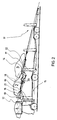
- FIG. 1 shows a two-story motor vehicle transporter 10 with a likewise two-story transport trailer 11.
- the transport trailer 11 corresponds to the prior art, so that a detailed description of the transport trailer 11 is unnecessary.
- the motor vehicle transporter 10 has a driver's cab superstructure 12 with a fixed platform 13. Opposite the direction of travel, the platform 13 of the driver's cab superstructure 12 is adjoined by a height-adjustable upper loading platform 14 which extends to the rear of the motor vehicle transporter 10. Below the upper loading platform 14, as in conventional motor vehicle transporters, there is a lower loading bridge 15.
- the upper loading platform 14 is held by lateral support arm pairs 16 and 17.
- the front bracket pair 16 is arranged immediately behind the cab superstructure 12, while the rear bracket pair 17 is arranged behind the rear axle of the motor vehicle transporter.
- the pairs of support arms used here are rigid columns in which a spindle drive for height adjustment of the upper loading platform 14 is provided. Such a height adjustment is basically known from the prior art.
- the upper loading platform 14 has an intermediate platform 18 between the platform 13 of the driver's cab superstructure 12 and the rear support arm pair 17.
- the intermediate platform can be arranged for loading, as shown in FIG. 1, in the plane of the loading platform 14.
- the intermediate stage 18 can be pivoted about a pivot axis 19 arranged transversely to the longitudinal axis of the transporter.
- the pivot axis 19 is arranged in the region of the front end of the loading platform 14, more precisely also in the front end of the intermediate platform 18.
- the intermediate stage 18 is mounted on the one hand in the pivot axis 19 on the loading platform 14 and on the other hand is held at the rear by schematically represented hydraulic cylinders 20.
- the intermediate platform is designed to be lowerable at the rear, the lowering movement being able to be brought about by adjusting the hydraulic cylinders 20.
- the intermediate platform 18 has an extendable connecting bridge 21 which, in the loading basic position shown in FIG. 1, establishes a connection between the platform 13 of the cab superstructure 12 and the intermediate platform 18.
- the connecting bridge 21 is shown in its extended position in FIG. 1.
- the rear area 22 of the loading platform 14 also has a retractable connecting bridge 23 at its front end.
- the connecting bridge 23 establishes a connection, at least in the loading basic position, between the front rear area 22, the upper loading platform 14 and the rear-side, lowerable part of the intermediate platform 18.
- the connecting bridge 21 can be hydraulically pushed in and out, while the connecting bridge 23 can be pushed in and out by hand.
- the rear end 24 of the rear region 22 of the upper loading platform 14 can be pulled out to the rear so that the total length of the upper loading platform 14 can be varied.
- the height adjustment device for the upper loading platform 14, consisting of the pairs of support arms 16 and 17, is designed, as will be explained in more detail later, in such a way that the loading platform 14 can be raised above the transport height.
- Fig. 1 the upper loading platform 14 is shown in the loading basic position, which is still arranged below the normal transport height.
- box rails 25 which can be lifted upward are arranged on the rear region 22 of the loading platform 14. In Fig. 1, these box rails 25 are lowered into the level of the loading platform 14.
- the box rails 25 are provided with attachable extensions 26 at their front ends.
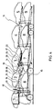
- the upper loading platform 14 is lowered so far that its front end is aligned with the platform 13 of the cab superstructure. From there, the upper loading platform 14 extends obliquely downward at the rear, so that a ramp is formed using the upper loading platform of the transport trailer 11. If the motor vehicle transporter 10 is used without a transport trailer 11, the upper loading platform 14 is inclined correspondingly steeper. In principle, there is no difference in loading.
- the intermediate platform 18 is pivoted into the plane of the upper loading platform 14 and the connecting bridge 21 pushed out.
- a first medium-sized car 1 is now driven over the upper loading platform 14 inclined as a ramp to the platform 13 and parked there.
- the connecting bridge 21 is first inserted into the intermediate stage 18.
- the upper loading platform 14 is then raised further upward, specifically in the region of the front end of the loading platform 14 beyond the transport height to its highest position.
- the other pairs of support arms 17 of the motor vehicle transporter 10 or those of the transport trailer 11 are moved accordingly, so that the upper loading platforms 14 continue to form a ramp.
- the second car is then driven backwards to the intermediate stage 18, specifically to the position indicated by the dash-dotted line in FIG. 2.
- the rear of the second vehicle lies above the front of the first vehicle without the first vehicle having to be maneuvered for it.
- the rear end of the intermediate platform 18 is then lowered downward about the pivot axis 19, specifically after the connecting bridge 23 of the rear region 22 has been inserted.
- the front part of the second vehicle now plunges into the level of the loading platform 14.
- the box rails 25 are lifted out of the level of the loading platform 14. Now the third vehicle is driven backwards onto the rear area 22 of the upper loading platform 14 such that the rear wheels are parked on the box rails 25. In this position, the rear of the third vehicle is arranged above the front of the second vehicle.
- both the upper loading platform 14 of the motor vehicle transporter 10 and the upper loading platform of the transport trailer 11 are raised to the uppermost position, specifically above the transport height.
- the remaining vehicles 6 to 9 are then moved in one after the other over the lower deck of the transport trailer to possibly onto the lower loading bridge 15 of the motor vehicle transporter 10.
- the upper loading platform 14 of the motor vehicle transporter 10 is then lowered again, so that the loaded transporter does not exceed a total height of approximately 4 m.
- the vehicles are unloaded in reverse order.
- the lower loading bridge 15 is emptied, specifically after the upper loading platform 14 has been raised again above the transport height. After emptying the lower loading bridge 15, the rear end of the upper loading platform 14 is lowered so far that vehicle 3 can drive down.
- vehicle 2 can also be lowered from the transporter.
- the front end of the loading platform 14 must finally be lowered so far that the loading platform 14 and platform 13 are flush with one another.
- the connecting bridge 21 has been pushed out, the vehicle 1 can then also leave the transporter.
Landscapes
- Engineering & Computer Science (AREA)
- Health & Medical Sciences (AREA)
- Public Health (AREA)
- Transportation (AREA)
- Mechanical Engineering (AREA)
- Auxiliary Methods And Devices For Loading And Unloading (AREA)
- Rollers For Roller Conveyors For Transfer (AREA)
- Types And Forms Of Lifts (AREA)
- Body Structure For Vehicles (AREA)
Claims (8)
- Véhicule à double pont pour le transport de véhicules à moteur comprenant une superstructure (12) de la cabine de conducteur et une plate-forme de chargement supérieure (14) réglable en hauteur qui se raccorde, du moins en position de chargement, à ladite superstructure ainsi qu'un pont de chargement inférieur (15), caractérisé en ce que la plate-forme de chargement (14) comprend, entre la superstructure (12) de la cabine de conducteur et une paire de bras de support (17) située à l'arrière, une plate-forme intermédiaire (18) montée de façon à pouvoir pivoter autour d'un axe de pivotement (19) placé transversalement à l'axe longitudinal du véhicule transporteur et pouvant être amenée pour le chargement dans le plan de la plate-forme de chargement (14) et qui est équipée à son extrémité antérieure d'un pont de liaison télescopique (21), un dispositif de réglage en hauteur (16,17) pour la plate-forme de chargement (14) étant réalisé de telle façon que la plate-forme de chargement (14) peut être relevée au-delà du niveau de transport.
- Véhicule transporteur selon la revendication 1, caractérisé en ce que la plate-forme intermédiaire (18) est conformée de façon à pouvoir être abaissée du côté arrière.
- Véhicule transporteur selon l'une des revendications 1 ou 2, caractérisé en ce que la plate-forme intermédiaire (18) est montée sur la plate-forme de chargement (14) au moyen de l'axe de pivotement (19) disposé transversalement à l'axe longitudinal du véhicule transporteur.
- Véhicule transporteur selon l'une des revendications 1 à 3, caractérisé en ce que l'axe de pivotement (19) est disposé dans la région de l'extrémité avant de la plate-forme de chargement.
- Véhicule transporteur selon l'une des revendications 1 à 4, caractérisé en ce que la plate-forme de chargement (14) est équipée à l'arrière de la plate-forme intermédiaire (18) de rails à emboîtement (25) pouvant être relevés.
- Véhicule transporteur selon la revendication 5, caractérisé en ce que les rails à emboîtement (25) sont munis de rallonges (26) accrochables.
- Véhicule transporteur selon l'une des revendications 1 à 6, caractérisé en ce que la plate-forme de chargement (14) est équipée à l'extrémité arrière (24) d'un pont de liaison télescopique.
- Véhicule transporteur selon l'une des revendications 1 à 7, caractérisé en ce qu'un pont de liaison télescopique (23) est disposé dans la section arrière de la plate-forme de chargement (14).
Applications Claiming Priority (2)
| Application Number | Priority Date | Filing Date | Title |
|---|---|---|---|
| DE8610072U | 1986-04-14 | ||
| DE8610072U DE8610072U1 (de) | 1986-04-14 | 1986-04-14 | Doppelstöckiger Kraftfahrzeugtransporter |
Publications (4)
| Publication Number | Publication Date |
|---|---|
| EP0241711A2 EP0241711A2 (fr) | 1987-10-21 |
| EP0241711A3 EP0241711A3 (en) | 1987-12-23 |
| EP0241711B1 EP0241711B1 (fr) | 1990-03-07 |
| EP0241711B2 true EP0241711B2 (fr) | 1993-11-18 |
Family
ID=6793619
Family Applications (1)
| Application Number | Title | Priority Date | Filing Date |
|---|---|---|---|
| EP87103555A Expired - Lifetime EP0241711B2 (fr) | 1986-04-14 | 1987-03-11 | Véhicule à double pont pour le transport de véhicules à moteur |
Country Status (3)
| Country | Link |
|---|---|
| EP (1) | EP0241711B2 (fr) |
| DE (2) | DE8610072U1 (fr) |
| ES (1) | ES2013734T5 (fr) |
Families Citing this family (11)
| Publication number | Priority date | Publication date | Assignee | Title |
|---|---|---|---|---|
| FR2618394A1 (fr) * | 1987-07-21 | 1989-01-27 | Levis Christian | Vehicule pour le transport d'autres vehicules |
| FR2635301B1 (fr) * | 1988-08-05 | 1990-10-26 | Lohr Ind | Convoi articule porte-voitures a plateaux porteurs individuels mobiles en mouvements composes |
| EP0464241A1 (fr) * | 1990-07-03 | 1992-01-08 | Kässbohrer-Austria Fahrzeugwerke GmbH | Véhicule pour le transport d'autres véhicules |
| FR2679499B1 (fr) * | 1991-07-24 | 1997-03-28 | Lohr Ind | Garde-corps escamotable pour unite routiere porte-vehicules. |
| DE9302474U1 (de) * | 1993-02-19 | 1994-06-23 | Kässbohrer-Austria Fahrzeugwerke Ges.m.b.H., Salzburg | Transportvorrichtung |
| IT1281091B1 (it) * | 1995-12-20 | 1998-02-11 | Rolfo Spa | Veicolo a due pianali sovrapposti per il trasporto di autoveicoli |
| NL1007191C2 (nl) * | 1997-10-01 | 1999-04-07 | Groenewold S Carrosseriefabrie | Dubbeldeks-autotransporteur. |
| US7025547B2 (en) | 2004-03-29 | 2006-04-11 | Boydstun Metal Works, Inc. | Vehicle transporter with screw actuators |
| US7575402B2 (en) | 2006-07-06 | 2009-08-18 | Toyota Motor Credit Corporation | Vehicle transporter with screw actuators |
| EP1927505A3 (fr) * | 2006-12-01 | 2008-07-30 | Franco Capetola | Camion à remorque destiné au transport de véhicules, tracteur et remorque correspondants tout comme procédé destiné à la décharge de la remorque |
| DE202012008603U1 (de) | 2012-09-07 | 2012-10-01 | KÄSSBOHRER TRANSPORT TECHNIK Ges.m.b.H. | Ladeplattform und Fahrzeugtransporter mit einer solchen Ladeplattform |
Family Cites Families (2)
| Publication number | Priority date | Publication date | Assignee | Title |
|---|---|---|---|---|
| US2694597A (en) * | 1950-10-02 | 1954-11-16 | Car Carrier Equipment Company | Vehicle transporting device |
| GB2139968A (en) * | 1983-04-29 | 1984-11-21 | York Technical Services Limite | Car transporters |
-
1986
- 1986-04-14 DE DE8610072U patent/DE8610072U1/de not_active Expired
-
1987
- 1987-03-11 EP EP87103555A patent/EP0241711B2/fr not_active Expired - Lifetime
- 1987-03-11 DE DE8787103555T patent/DE3761810D1/de not_active Expired - Lifetime
- 1987-03-11 ES ES87103555T patent/ES2013734T5/es not_active Expired - Lifetime
Also Published As
| Publication number | Publication date |
|---|---|
| EP0241711B1 (fr) | 1990-03-07 |
| DE3761810D1 (de) | 1990-04-12 |
| ES2013734T5 (es) | 1995-08-16 |
| ES2013734B3 (es) | 1990-06-01 |
| DE8610072U1 (de) | 1986-05-28 |
| EP0241711A2 (fr) | 1987-10-21 |
| EP0241711A3 (en) | 1987-12-23 |
Similar Documents
| Publication | Publication Date | Title |
|---|---|---|
| DE69107678T2 (de) | Ladeplattform mit automatischer Barriere für Fahrzeuge. | |
| DE2731386C2 (fr) | ||
| DE4447860C2 (de) | Schleppfahrzeug zum Manövrieren von Flugzeugen | |
| EP0284836A1 (fr) | Véhicule de manutention pour manoeuvrer les avions au sol | |
| EP0241711B2 (fr) | Véhicule à double pont pour le transport de véhicules à moteur | |
| DE102004018910A1 (de) | Flurfolgefahrzeug | |
| DE19823380A1 (de) | Vorrichtung zur Verringerung der Achslast eines mehrachsigen fahrbaren Teleskopkranes | |
| DE3320332C1 (de) | Verfahren zum Beladen eines Behaeltnisses mit Fahrzeugen | |
| DE69011518T2 (de) | Sattelanhänger. | |
| DE2632492C3 (de) | Transportfahrzeug zum Transport von Großbehältern | |
| DE1918600B1 (de) | Fahrzeug mit ablegbarer Rampe zum Bilden von Bruecken,insbesondere Schwimmbruecken,und Faehren | |
| DE4415405C2 (de) | Schleppfahrzeug zum Manövrieren von Flugzeugen | |
| DE3336638C2 (de) | Fahrzeugkran hoher Traglast mit verlängerbarem Ausleger, insbesondere Teleskopausleger | |
| DE69517580T2 (de) | Behälter-kombination und verfahren zum handhaben von behältern | |
| EP0464241A1 (fr) | Véhicule pour le transport d'autres véhicules | |
| EP3683094B1 (fr) | Transporteur de véhicule à dispositif d'empilement | |
| DE2147926A1 (de) | Fahrzeug mit daran angebrachter Ladeplattform | |
| DE8011609U1 (de) | Fahrzeug fuer den transport von personenkraftwagen | |
| DE29620358U1 (de) | Transportfahrzeug, insbesondere Lastkraftwagen oder Anhänger, mit einer Ladefläche und mit mindestens einer Auffahrrampe | |
| DE1811052C3 (de) | Doppelstückiges Mehrzweckfahrzeug, insbesondere für den Behälter- und Autotransport | |
| DE8519969U1 (de) | Doppelstöckiger Pkw-Transporter mit einem Anhänger | |
| DE2929336C2 (fr) | ||
| DE2328818C2 (de) | Fahrzeug für den Transport von Stahlbetonraumzellen, insbesondere Transformatorenhäuschen | |
| DE2908465A1 (de) | Fahrzeug zum transport von personenkraftwagen | |
| WO1990005074A1 (fr) | Plateau coulissant pour vehicules transportant des charges lourdes, des automobiles en particulier |
Legal Events
| Date | Code | Title | Description |
|---|---|---|---|
| PUAI | Public reference made under article 153(3) epc to a published international application that has entered the european phase |
Free format text: ORIGINAL CODE: 0009012 |
|
| AK | Designated contracting states |
Kind code of ref document: A2 Designated state(s): BE DE ES FR GB IT NL |
|
| PUAL | Search report despatched |
Free format text: ORIGINAL CODE: 0009013 |
|
| ITCL | It: translation for ep claims filed |
Representative=s name: GILBERTO PETRAZ |
|
| AK | Designated contracting states |
Kind code of ref document: A3 Designated state(s): BE DE ES FR GB IT NL |
|
| TCNL | Nl: translation of patent claims filed | ||
| EL | Fr: translation of claims filed | ||
| 17P | Request for examination filed |
Effective date: 19880224 |
|
| 17Q | First examination report despatched |
Effective date: 19881028 |
|
| GRAA | (expected) grant |
Free format text: ORIGINAL CODE: 0009210 |
|
| ITF | It: translation for a ep patent filed | ||
| AK | Designated contracting states |
Kind code of ref document: B1 Designated state(s): BE DE ES FR GB IT NL |
|
| ET | Fr: translation filed | ||
| GBT | Gb: translation of ep patent filed (gb section 77(6)(a)/1977) | ||
| REF | Corresponds to: |
Ref document number: 3761810 Country of ref document: DE Date of ref document: 19900412 |
|
| PLBI | Opposition filed |
Free format text: ORIGINAL CODE: 0009260 |
|
| 26 | Opposition filed |
Opponent name: LOHR INDUSTRIE Effective date: 19901204 |
|
| NLR1 | Nl: opposition has been filed with the epo |
Opponent name: LOHR INDUSTRIE. |
|
| ITTA | It: last paid annual fee | ||
| PLAB | Opposition data, opponent's data or that of the opponent's representative modified |
Free format text: ORIGINAL CODE: 0009299OPPO |
|
| D26 | Opposition filed (deleted) | ||
| PUAH | Patent maintained in amended form |
Free format text: ORIGINAL CODE: 0009272 |
|
| STAA | Information on the status of an ep patent application or granted ep patent |
Free format text: STATUS: PATENT MAINTAINED AS AMENDED |
|
| ITF | It: translation for a ep patent filed | ||
| 27A | Patent maintained in amended form |
Effective date: 19931118 |
|
| AK | Designated contracting states |
Kind code of ref document: B2 Designated state(s): BE DE ES FR GB IT NL |
|
| GBTA | Gb: translation of amended ep patent filed (gb section 77(6)(b)/1977) |
Effective date: 19931027 |
|
| ET3 | Fr: translation filed ** decision concerning opposition | ||
| NLR2 | Nl: decision of opposition | ||
| NLR3 | Nl: receipt of modified translations in the netherlands language after an opposition procedure | ||
| REG | Reference to a national code |
Ref country code: FR Ref legal event code: TP |
|
| REG | Reference to a national code |
Ref country code: GB Ref legal event code: 732E |
|
| NLS | Nl: assignments of ep-patents |
Owner name: KAESSBOHRER TRANSPORT TECHNIK GMBH |
|
| REG | Reference to a national code |
Ref country code: ES Ref legal event code: PC2A Owner name: KASSBOHRER TRANSPORT TECHNIK GMBH |
|
| PGFP | Annual fee paid to national office [announced via postgrant information from national office to epo] |
Ref country code: ES Payment date: 19970310 Year of fee payment: 11 |
|
| PGFP | Annual fee paid to national office [announced via postgrant information from national office to epo] |
Ref country code: GB Payment date: 19980216 Year of fee payment: 12 |
|
| PGFP | Annual fee paid to national office [announced via postgrant information from national office to epo] |
Ref country code: BE Payment date: 19980327 Year of fee payment: 12 |
|
| PGFP | Annual fee paid to national office [announced via postgrant information from national office to epo] |
Ref country code: NL Payment date: 19980331 Year of fee payment: 12 |
|
| PG25 | Lapsed in a contracting state [announced via postgrant information from national office to epo] |
Ref country code: GB Free format text: LAPSE BECAUSE OF NON-PAYMENT OF DUE FEES Effective date: 19990311 |
|
| PG25 | Lapsed in a contracting state [announced via postgrant information from national office to epo] |
Ref country code: ES Free format text: LAPSE BECAUSE OF NON-PAYMENT OF DUE FEES Effective date: 19990312 |
|
| PGFP | Annual fee paid to national office [announced via postgrant information from national office to epo] |
Ref country code: FR Payment date: 19990317 Year of fee payment: 13 |
|
| PG25 | Lapsed in a contracting state [announced via postgrant information from national office to epo] |
Ref country code: BE Free format text: LAPSE BECAUSE OF NON-PAYMENT OF DUE FEES Effective date: 19990331 |
|
| PGFP | Annual fee paid to national office [announced via postgrant information from national office to epo] |
Ref country code: DE Payment date: 19990428 Year of fee payment: 13 |
|
| BERE | Be: lapsed |
Owner name: KASSBOHRER-AUSTRIA FAHRZEUGWERKE G.M.B.H. Effective date: 19990331 |
|
| PG25 | Lapsed in a contracting state [announced via postgrant information from national office to epo] |
Ref country code: NL Free format text: LAPSE BECAUSE OF NON-PAYMENT OF DUE FEES Effective date: 19991001 |
|
| GBPC | Gb: european patent ceased through non-payment of renewal fee |
Effective date: 19990311 |
|
| NLV4 | Nl: lapsed or anulled due to non-payment of the annual fee |
Effective date: 19991001 |
|
| PLAB | Opposition data, opponent's data or that of the opponent's representative modified |
Free format text: ORIGINAL CODE: 0009299OPPO |
|
| R26 | Opposition filed (corrected) |
Opponent name: SOLVAY (SOCIETE ANONYME), BRUXELLES Effective date: 19901204 |
|
| PG25 | Lapsed in a contracting state [announced via postgrant information from national office to epo] |
Ref country code: FR Free format text: LAPSE BECAUSE OF NON-PAYMENT OF DUE FEES Effective date: 20001130 |
|
| REG | Reference to a national code |
Ref country code: FR Ref legal event code: ST |
|
| PG25 | Lapsed in a contracting state [announced via postgrant information from national office to epo] |
Ref country code: DE Free format text: LAPSE BECAUSE OF NON-PAYMENT OF DUE FEES Effective date: 20010103 |
|
| REG | Reference to a national code |
Ref country code: ES Ref legal event code: FD2A Effective date: 20010503 |
|
| PG25 | Lapsed in a contracting state [announced via postgrant information from national office to epo] |
Ref country code: IT Free format text: LAPSE BECAUSE OF NON-PAYMENT OF DUE FEES Effective date: 20050311 |