EP0241449B1 - Resistance multi-spot welding machine - Google Patents
Resistance multi-spot welding machine Download PDFInfo
- Publication number
- EP0241449B1 EP0241449B1 EP87890037A EP87890037A EP0241449B1 EP 0241449 B1 EP0241449 B1 EP 0241449B1 EP 87890037 A EP87890037 A EP 87890037A EP 87890037 A EP87890037 A EP 87890037A EP 0241449 B1 EP0241449 B1 EP 0241449B1
- Authority
- EP
- European Patent Office
- Prior art keywords
- feed
- crosswires
- wire
- welding
- welding machine
- Prior art date
- Legal status (The legal status is an assumption and is not a legal conclusion. Google has not performed a legal analysis and makes no representation as to the accuracy of the status listed.)
- Expired
Links
- 238000003466 welding Methods 0.000 title claims abstract description 45
- 238000004519 manufacturing process Methods 0.000 claims abstract description 4
- 238000012546 transfer Methods 0.000 claims description 4
- 230000029305 taxis Effects 0.000 claims 1
- 239000000969 carrier Substances 0.000 description 2
- 230000015572 biosynthetic process Effects 0.000 description 1
- 239000004020 conductor Substances 0.000 description 1
- 238000013461 design Methods 0.000 description 1
- 230000000694 effects Effects 0.000 description 1
- 238000012423 maintenance Methods 0.000 description 1
- 239000002184 metal Substances 0.000 description 1
- 238000000034 method Methods 0.000 description 1
- 238000012986 modification Methods 0.000 description 1
- 230000004048 modification Effects 0.000 description 1
- 238000004804 winding Methods 0.000 description 1
Images


Classifications
-
- B—PERFORMING OPERATIONS; TRANSPORTING
- B21—MECHANICAL METAL-WORKING WITHOUT ESSENTIALLY REMOVING MATERIAL; PUNCHING METAL
- B21F—WORKING OR PROCESSING OF METAL WIRE
- B21F27/00—Making wire network, i.e. wire nets
- B21F27/08—Making wire network, i.e. wire nets with additional connecting elements or material at crossings
- B21F27/10—Making wire network, i.e. wire nets with additional connecting elements or material at crossings with soldered or welded crossings
-
- B—PERFORMING OPERATIONS; TRANSPORTING
- B23—MACHINE TOOLS; METAL-WORKING NOT OTHERWISE PROVIDED FOR
- B23K—SOLDERING OR UNSOLDERING; WELDING; CLADDING OR PLATING BY SOLDERING OR WELDING; CUTTING BY APPLYING HEAT LOCALLY, e.g. FLAME CUTTING; WORKING BY LASER BEAM
- B23K11/00—Resistance welding; Severing by resistance heating
- B23K11/002—Resistance welding; Severing by resistance heating specially adapted for particular articles or work
- B23K11/008—Manufacturing of metallic grids or mats by spot welding
Definitions
- the invention relates to a multi-point resistance welding machine for producing grids, which consist of longitudinal and transverse wires crossing at right angles and welded to one another at the crossing points, with two feed devices for the cross wires and one for removing the cross wires individually from the feed devices and into the welding area between them Electrode-transferring conveyor.
- Such a machine is known for example from AT-B-267 292.
- the transverse wires are shot from the side into guides arranged at a distance from the welding electrodes, then lifted out of the weft guides by transport rails provided with appropriately shaped hooks and from these rails into the area between two rows of double-point welding lines in the longitudinal wire direction Supported welding electrodes.
- Two cross wires of the same length are thus shot in at the same time and also welded to the family of longitudinal wires at the same time, which is why such a machine allows very high production speeds, on the other hand it is limited to the production of grid tracks in which the cross wires extend over the entire grid width.
- grids are required, for which this is not the case and, for example, twice as many transverse wires are to be provided on each side of the longitudinal central axis of a grid mat on one third of the mat width as along the two mat edges that are one sixth of the mat width, or grids for which over a large part of the mat width, viewed from a grid edge, twice as many cross wires as should be provided on the opposite mat edge.
- the invention is therefore concerned with the task of designing a grid welding machine of the type specified in the introduction, that is to say a machine with two feed devices for transverse wires, in such a way that transverse wires of different lengths can be arranged in one and the same grid path and that all transverse wires and their length is smaller than the total width of the grid, can be arranged in any position with respect to the longitudinal central axis of this grid.
- At least one of the two feed devices for the transverse wires is designed to be displaceable and lockable in a guide transverse to the feed path of the longitudinal wire family and relative to the conveying device which transfers the transverse wires into the welding area.
- cross wires of different lengths can be removed from separate magazines and brought into the effective area of the conveyor device transmitting them to the welding area by the assigned feed devices, or, as is also known per se, straight wires can be fed in from a machine side guides cooperating with the conveyor are inserted and cut as required into cross wires of the desired length.
- cross wire feeders can also be combined.
- a lateral wire feed is preferably used for the or for each cross-adjustable feed device, with scissors being mounted on the input of the feed device, which, after program-controlled advancement of a desired wire section in the feed device, executes a program-controlled scissor cut, so that it performs a certain desired position in the transverse direction engaging feeder is each loaded with a cross wire of the desired length in the desired relative position with respect to the feed path of the longitudinal wire coulter.
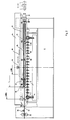
- the electrode bar 2 which carries the upper electrodes 3, can be seen in FIGS. 1 and 3.
- the electrode bar 2 can be moved up and down and the electrodes 3 can be resiliently supported in it, or it can be designed to be stationary and, in the interior, support the electrodes against the weld metal and lift it off again, for example hydraulic working cylinders.
- the lower electrodes 4 are supported on a machine-fixed support 5, which in turn rests on a wall 6 running across the entire width of the machine housing, to which it transmits the welding pressure.
- the lower electrodes 4 are alternately connected in opposite directions to the secondary windings of transformers 8 via flexible leads 7.
- the upper electrodes 3 are connected via flexible feed lines 9 in a known manner to a compensating conductor (not shown), which preferably extends over the entire machine width, and form the passive electrodes of double-point welding sections oriented in the direction of the machine width.
- the arrangement and electrical feed of the electrodes described is only one embodiment, which does not limit the applicability of the invention.
- As part of the The invention can of course be used for any other customary and expedient way of arranging the electrodes and supplying them with energy, in particular with the formation of single-point welding sections.
- a beam 14 (FIGS. 3 and 4) fastened at both ends in the machine housing and extending over the entire width of the machine carries a first cross-wire feed device 16 in a guide 15.
- This feed device 16 is in the guide 15 by means of a second, in Cross-section T-shaped bar 17 suspended, which is connected at its top to a rack 18.
- the pinion 19 of an electric motor 20, which is arranged on the bar 14, extends through a passage opening in the bottom of the bar 14 and meshes with the rack 18.
- the motor 20 and the pinion 19 engaging in the rack 18 the bar 17 and can the entire cross wire feed device 16 in the guide 15 in FIGS. 3 and 4 can be moved forwards and backwards or in FIGS. 1 and 2 to the right and left. This shift preferably takes place under the control effect of a program control device not forming the subject of the invention and therefore also not shown.
- the limit positions of the shift are indicated in FIG. 2 by the arrows Lmax and Lmin.
- the latter limit position in particular is determined by the arrangement of the pinion 19 on the bar 14.
- this pinion 19 is arranged in the middle of the machine; however, it could just as well be arranged off-center, for example offset in the direction of the right side boundary of the machine in FIG. 2, whereby L min would likewise be moved further to the right.
- Connections 21 arranged at intervals along the beam 17 carry a carrier 27 (FIGS. 3 and 4), along which guide strips 30 are arranged at smaller mutual intervals.
- connecting pieces 22 are also provided along the beam 17, at the lower ends of which a shaft 23 is supported, which in its sections lying between the connecting pieces 22 is surrounded by rollers 24 connected to it in a rotationally fixed manner.
- Each roller 24 is provided with axially parallel grooves 25, which are arranged at equal angular intervals along its circumference and are used to hold grid cross wires 26.
- the spaced-apart guide strips 30 close the grooves 25 downward in order to prevent the cross wires from falling out of the grooves prematurely and undesirably.
- a motor 31 (FIG. 1) is arranged, which is connected in a rotationally fixed manner to the shaft 23 and, as soon as a cross wire 26 is to be removed from one of the grooves 25, program-controlled by one step, corresponding to the angular distance between two along of the roller circumference of adjacent grooves, continues to rotate.
- a straight wire 32 is inserted into an overlying groove 25 of the rollers 24 from the machine side opposite the motor 31.
- To feed the wire 32 are provided on the machine housing according to FIG. 2 drivable for rotation, detecting the wire by means of a clamping connection and program-controlled feed rollers 33 as well as a measuring roller 34 which reports the travel path of the wire of the control device.
- a pair of transverse wires 26 of the desired length can be separated from the incoming wire 32 by a pair of scissors 35 arranged in the wire feed path.
- the scissors 35 like the motor 31, are arranged so as to be movable on the beam 17.
- the position of the first cross wire feed device 16, which is reported by an encoder coupled to the pinion 19, is compared with the desired cross wire length recorded in an input device, and the required feed distance of the wire 32 is determined therefrom. so that, for example in FIG. 2, a cross wire 26 of the desired length comes to lie to the right of the scissors 35 in each of the grooves 25.
- a second cross wire feed device 40 is fed with straight, cut cross wires 41 of the same length throughout.
- the feed device 40 can have the structure known from AT-B-368 414. It is therefore sufficient in the present context to describe this feed device on the basis of the schematic illustration in FIGS. 3 and 4 only as far as is necessary to understand the invention. Accordingly, the second feed device 40 consists essentially of endless link chains 44 which are wound around chain wheels 42 and 43 and which hold receiving compartments 45 for transverse wires 41 at mutual intervals. These cross wires 41 are in a known manner near the upper sprockets 41 driven individually by a cardan shaft 46, z. B.
- a magazine 47 indicated only schematically, introduced into the receiving compartments 45 and fed by means of the link chains 44 to a conveyor device 60, which optionally has transverse wires 26 or 41 of generally different lengths and different relative positions with respect to the feed path of the longitudinal wire array from the first feed device 16 or receives from the second feed device 40.
- the axes of the chain wheels 42 and 43 of the feed device 40, the wire magazine 47 and the device (not shown because known per se) for transferring individual wires from the magazine 47 into the receiving compartments 45 are carried by two carriers 48.
- the carriers 48 are mounted on a carriage 50 by means of a linkage 49, which can be displaced in the direction transverse to the welding machine by means of rollers 51 on rails 52.
- This shift which affects the positioning of the cut Qu Wires 41 in the desired position within the grid 55 to be produced, for example in a position offset laterally by a distance e from the longitudinal center axis of the grid 55, are carried out with the aid of an optionally motor-controlled electric motor 54 which interacts with a toothed rack 53.
- a platform supporting the cross rails 52 56, on which a receptacle 59 for a wire supply feeding the magazine 47 is also arranged, can be displaced by means of rollers 57 on longitudinal rails 58 in the direction of the feed device 16 or away from it.
- this displaceability only serves to facilitate any maintenance work that may be necessary on the two feed devices 16 and 40.
- a non-displaceably arranged conveyor device 60 extends across the width of the welding machine.
- the conveyor device 60 consists of a shaft 61 which can be driven in the welding cycle of the machine and along which disks 62 are arranged at intervals.
- the disks 62 have slots 63 along their circumferences at equal angular intervals in alignments parallel to the shaft 61, each for receiving a transverse wire, etc. either a cross wire 26 from the feed device 16 or a cross wire 41 from the feed device 40.
- the choice of whether a cross wire 26 or a cross wire 41 is fed into one of the slots 63 is made in a program-controlled manner by means of the drive of the shaft 23 or the link chains 44.
- Cover plates 65 are provided at intervals along a support 64, which prevent the transverse wires from falling out of the slots 63 prematurely.
- Spaced fingers 66 which engage in the spaces between the disks 62 are arranged on a beam 67 which extends across the machine width and can be rotated about its axis and, by means of a pivoting movement in time with the welding machine, convey the wires from the bottom of the slots 63 along guides 68 in the area between the welding electrodes 3, 4 and place them there on the longitudinal wires 70.
- the shaft 61 is in the work cycle of the welding machine, i.e. after each welding operation, an angular amount which is equal to the central angle between two adjacent slots 63 is advanced.
- the welding machine can only be fed with cross wires 41 cut to length from the feed device 40 if, during each idle period of the shaft 61, the link chains 44 are moved further by one step, which is equal to the distance between two successive receiving compartments 45, and thus one cross wire 41 each pass from the lowest receiving compartment 45 to the slots 63 of the disks 62.
- grids can also be produced, for example, in which rods 26 and 41 are arranged in a constant alternation.
- the shaft 23 and the link chains 44 are simultaneously advanced by one step and each transfer a cross wire into one of two adjacent alignments of slots 63.
- the transfer of wires from the feed devices 16 and 40, respectively the conveyor device 60 can also be effected in any order by a program control device.
- the length of the transverse wires 26 fed to the feed device 16 and cut to length by the shear 35 from the incoming wire 32 can also be determined in each individual case by the program control device, as can the respective position of the feed devices 16 and 40 with respect to the welding machine axis.
- this grid can be used to produce its cross wires within one and the same grid path, not only with regard to their length. but also differentiate in terms of their position with respect to the longitudinal central axis of the grid.
- the invention can also be used in lattice welding machines which, like the machine according to AT-B-267 292 cited in the introduction, have two parallel rows of welding electrodes.
- two associated transverse wires of selectable different lengths are then conveyed simultaneously by means of transport rails, at least one of the cross wires being able to move the transport rails via a crosswise to the feed path of the longitudinal wire family , either from the side with a wire to be cut, the feed device, similar to the described feed device 16, or in the longitudinal wire direction, from a magazine supplied feed device, similar to the described feed device 40, is program-controlled.
- the feed devices similar to the described feed device 16, or in the longitudinal wire direction, from a magazine supplied feed device, similar to the described feed device 40, is program-controlled.
Abstract
Description
Die Erfindung betrifft eine Vielpunkt-Widerstandsschweißmaschine zum Herstellen von Gittern, die aus einander rechtwinkelig kreuzenden und an den Kreuzungspunkten miteinander verschweißten Längs- und Querdrähten bestehen, mit zwei Zuführeinrichtungen für die Querdrähte und einer die Querdrähte einzeln aus den Zuführeinrichtungen entnehmenden und in den Schweißbereich zwischen den Elektroden übertragenden Fördereinrichtung.The invention relates to a multi-point resistance welding machine for producing grids, which consist of longitudinal and transverse wires crossing at right angles and welded to one another at the crossing points, with two feed devices for the cross wires and one for removing the cross wires individually from the feed devices and into the welding area between them Electrode-transferring conveyor.
Eine derartige Maschine ist beispielsweise aus der AT-B-267 292 bekannt. Bei der bekannten Maschine werden die Querdrähte von der Seite her in mit Abstand vor den Schweißelektroden angeordnete Führungen eingeschossen, sodann von mit entsprechend geformten Haken versehenen Transportschienen aus den Einschußführungen herausgehoben und von diesen Schienen in den Bereich zwischen zwei Doppelpunkt-Schweißstrecken in Längsdrahtrichtung bildenden Reihen von Schweißelektroden gefördert. Es werden somit jeweils zwei gleich lange Querdrähte gleichzeitig eingeschossen und auch gleichzeitig an die Schar der Längsdrähte angeschweißt, weshalb eine solche Maschine sehr hohe Produktionsgeschwindigkeiten zuläßt, anderseits auf die Produktion von Gitterbahnen beschränkt ist, bei welchen sich die Querdrähte über die gesamte Gitterbreite erstrecken. Häufig werden jedoch Gitter gefordert, bei welchen dies nicht der Fall ist und beispielsweise beidseits der Längsmittelachse einer Gittermatte auf je einem Drittel der Mattenbreite doppelt so viele Querdrähte vorgesehen werden sollen wie längs der beiden ein Sechstel der Mattenbreite betragenden Mattenränder, oder Gitter, bei welchen über einen Großteil der Mattenbreite, von einem Gitterrand weg betrachtet, doppelt so viele Querdrähte wie am gegenüberliegenden Mattenrand vorgesehen sein sollen.Such a machine is known for example from AT-B-267 292. In the known machine, the transverse wires are shot from the side into guides arranged at a distance from the welding electrodes, then lifted out of the weft guides by transport rails provided with appropriately shaped hooks and from these rails into the area between two rows of double-point welding lines in the longitudinal wire direction Supported welding electrodes. Two cross wires of the same length are thus shot in at the same time and also welded to the family of longitudinal wires at the same time, which is why such a machine allows very high production speeds, on the other hand it is limited to the production of grid tracks in which the cross wires extend over the entire grid width. Often, however, grids are required, for which this is not the case and, for example, twice as many transverse wires are to be provided on each side of the longitudinal central axis of a grid mat on one third of the mat width as along the two mat edges that are one sixth of the mat width, or grids for which over a large part of the mat width, viewed from a grid edge, twice as many cross wires as should be provided on the opposite mat edge.
Die Erfindung befaßt sich deshalb mit der Aufgabe, eine Gitterschweißmaschine der einleitend angegebenen Gattung, also eine Maschine mit zwei Zuführeinrichtungen für Querdrähte, derart auszugestalten, daß mit ihr Querdrähte mit unterschiedlichen Längen in ein und derselben Gitterbahn angeordnet werden können und daß alle Querdrähte, deren Länge geringer als die Gesamtbreite der Gitterbahn ist, bezüglich der Längsmittelachse dieser Gitterbahn in beliebiger Lage angeordnet werden können.The invention is therefore concerned with the task of designing a grid welding machine of the type specified in the introduction, that is to say a machine with two feed devices for transverse wires, in such a way that transverse wires of different lengths can be arranged in one and the same grid path and that all transverse wires and their length is smaller than the total width of the grid, can be arranged in any position with respect to the longitudinal central axis of this grid.
Gelöst wird diese Aufgabe dadurch, daß zumindest eine der beiden Zuführeinrichtungen für die Querdrähte quer zum Vorschubweg der Längsdrahtschar und relativ zu der die Querdrähte in den Schweißbereich übertragenden Fördereinrichtung in einer Führung verschiebbar und feststellbar ausgebildet ist.This object is achieved in that at least one of the two feed devices for the transverse wires is designed to be displaceable and lockable in a guide transverse to the feed path of the longitudinal wire family and relative to the conveying device which transfers the transverse wires into the welding area.
Die Querdrähte unterschiedlicher Länge können dabei, wie an sich bekannt, aus getrennten Magazinen entnommen und durch die zugeordneten Zuführeinrichtungen in den Wirkungsbereich der sie zum Schweißbereich übertragenden Fördereinrichtung gebracht werden, oder es können, wie ebenfalls an sich bekannt, geradegerichtete Drähte von einer Maschinenseite her in mit der Fördereinrichtung zusammenwirkende Führungen eingeschoben und nach Bedarf zu Querdrähten gewünschter Länge zugeschnitten werden. Diese beiden Arten von Querdraht-Zuführeinrichtungen können auch miteinander kombiniert werden. Vorzugsweise wird für die bzw. für jede querverstellbare Zuführeinrichtung eine seitliche Drahtzufuhr angewendet, wobei am Eingang der Zuführeinrichtung an dieser eine Schere montiert ist, die nach programmgesteuertem Vorschub eines gewünschten Drahtabschnittes in der Zuführeinrichtung einen programmgesteuerten Scherenschnitt ausführt, so daß die eine bestimmte Sollage in Querrichtung einnehmende Zuführeinrichtung jeweils mit einem Querdraht gewünschter Länge in gewünschter Relativlage bezüglich des Vorschubweges der Längsdrahtschar beschickt wird.As is known per se, the cross wires of different lengths can be removed from separate magazines and brought into the effective area of the conveyor device transmitting them to the welding area by the assigned feed devices, or, as is also known per se, straight wires can be fed in from a machine side guides cooperating with the conveyor are inserted and cut as required into cross wires of the desired length. These two types of cross wire feeders can also be combined. A lateral wire feed is preferably used for the or for each cross-adjustable feed device, with scissors being mounted on the input of the feed device, which, after program-controlled advancement of a desired wire section in the feed device, executes a program-controlled scissor cut, so that it performs a certain desired position in the transverse direction engaging feeder is each loaded with a cross wire of the desired length in the desired relative position with respect to the feed path of the longitudinal wire coulter.
Ein einfaches Ausführungsbeispiel einer erfindungsgemäßen Gitterschweißmaschine mit nur einer Elektrodenreihe wird nun anhand der Zeichnungen näher beschrieben. Es zeigen:
Figur 1 eine Draufsicht auf die Schweißmaschine,Figur 2 einen Schnitt nach der Linie 11 II inFigur 1,Figur 3 einen Schnitt nach der Linie lll - 111 inFigur 1 und Figur 4 die wesentlichen der inFigur 3 ersichtlichen Teile in größerem Maßstab.
- FIG. 1 shows a top view of the welding machine,
- FIG. 2 shows a section along the line 11 II in FIG. 1,
- 3 shows a section along the line III-111 in FIG. 1 and FIG. 4 shows the essential parts shown in FIG. 3 on a larger scale.
An der Schweißmaschine 1 erkennt man in den Figuren 1 und 3 den Elektrodenbalken 2, der die oberen Elektroden 3 trägt. Der Elektrodenbalken 2 kann auf- und abbewegbar sein und die Elektroden 3 können in ihm federnd abgestützt sein, oder er kann feststehend ausgebildet sein und im Inneren die Elektroden an das Schweißgut anstellende und von diesen wieder abhebende, beispielsweise hydraulische Arbeitszylinder tragen. Die unteren Elektroden 4 sind an einem maschinenfesten Träger 5 abgestützt, welcher seinerseits auf einer quer über die gesamte Breite des Maschinengehäuses verlaufenden Wand 6 ruht, auf welche er den Schweißdruck überträgt.On the
Über flexible Zuleitungen 7 sind in bekannter Weise die unteren Elektroden 4, abwechselnd gegensinnig gepolt, an die Sekundärwicklungen von Transformatoren 8 angeschlossen. Die oberen Elektroden 3 sind über flexible Zuleitungen 9 in bekannter Weise mit einem nicht dargestellten, sich vorzugsweise über die gesamte Maschinenbreite erstreckenden Ausgleichsleiter verbunden und bilden die passiven Elektroden von in Richtung der Maschinenbreite orientierten Doppelpunkt-Schweißstrecken.The lower electrodes 4 are alternately connected in opposite directions to the secondary windings of
Die beschriebene Anordnung und elektrische Anspeisung der Elektroden ist jedoch nur eine die Anwendbarkeit der Erfindung nicht begrenzende, beispielsweise Ausführungsform. Im Rahmen der Erfindung ist selbstverständlich jede andere gebräuchliche und zweckmäßige Art der Anordnung der Elektroden und deren Versorgung mit Energie, insbesondere unter Bildung von Einzelpunkt-Schweißstrecken, anwendbar.However, the arrangement and electrical feed of the electrodes described is only one embodiment, which does not limit the applicability of the invention. As part of the The invention can of course be used for any other customary and expedient way of arranging the electrodes and supplying them with energy, in particular with the formation of single-point welding sections.
Ein an seinen beiden Enden im Maschinengehäuse befestigter, sich über die gesamte Breite der Maschine erstreckender Balken 14 (Figuren 3 und 4) trägt in einer Führung 15 eine erste Querdraht-Zuführeinrichtung 16. Diese Zuführeinrichtung 16 ist in der Führung 15 mittels eines zweiten, im Querschnitt T-förmigen Balkens 17 aufgehängt, der an seiner Oberseite mit einer Zahnstange 18 verbunden ist. Das Ritzel 19 eines Elektromotors 20, der am Balken 14 angeordnet ist, greift durch eine Durchtrittsöffnung im Boden des Balkens 14 hindurch und kämmt mit der Zahnstange 18. Mittels des Motors 20 und des in die Zahnstange 18 eingreifenden Ritzels 19 kann der Balken 17 und mit ihm die ganze Querdraht-Zuführeinrichtung 16 in der Führung 15 in den Figuren 3 und 4 nach vorn und hinten bzw. in den Figuren 1 und 2 nach rechts und links verschoben werden. Diese Verschiebung erfolgt vorzugsweise unter der Steuerwirkung einer nicht Gegenstand der Erfindung bildenden und deshalb auch nicht dargestellten Programmsteuereinrichtung.A beam 14 (FIGS. 3 and 4) fastened at both ends in the machine housing and extending over the entire width of the machine carries a first
Die Grenzlagen der Verschiebung sind in Figur 2 durch die Pfeile Lmax bzw. Lmin angedeutet. Insbesondere die letztere Grenzlage wird durch die Anordnung des Ritzels 19 am Balken 14 bestimmt. In Figur 2 wurde angenommen, daß dieses Ritzel 19 in der Maschinenmitte angeordnet ist; es könnte aber ebensogut auch außermittig, etwa in Figur 2 in Richtung zur rechten Seitenbegrenzung der Maschine versetzt, angeordnet werden, wodurch Lmin gleichfalls weiter nach rechts verlegt würde.The limit positions of the shift are indicated in FIG. 2 by the arrows Lmax and Lmin. The latter limit position in particular is determined by the arrangement of the
In Abständen längs des Balkens 17 angeordnete Verbindungsstücke 21 tragen einen Träger 27 (Figuren 3 und 4), längs welchem in kleineren gegenseitigen Abständen angeordnete Führungsleisten 30 befestigt sind. Gegenüber den Verbindungsstücken 21 sind längs des Balkens 17 noch Verbindungsstücke 22 vorgesehen, an deren unteren Enden eine Welle 23 gelagert ist, die in ihren zwischen den Verbindungsstücken 22 liegenden Abschnitten von drehfest mit ihr verbundenen Walzen 24 umgeben ist. Jede Walze 24 ist mit in gleichen Winkelabständen längs ihres Umfanges angeordneten, achsparallelen Nuten 25 versehen, die zur Aufnahme von Gitterquerdrähten 26 dienen. Die in Abständen angeordneten Führungsleisten 30 verschließen die Nuten 25 nach unten hin, um ein vorzeitiges, unerwünschtes Herausfallen der Querdrähte aus den Nuten zu verhindern.
An einem Ende des Balkens 17 ist ein Motor 31 (Figur 1) angeordnet, der drehfest mit der Welle 23 verbunden ist und diese, sobald ein Querdraht 26 aus einer der Nuten 25 entnommen werden soll, programmgesteuert um einen Schritt, entsprechend dem Winkelabstand zweier längs des Walzenumfanges benachbarter Nuten, weiterdreht. Längs der Linie E in Figur 1 wird von der dem Motor 31 gegenüberliegenden Maschinenseite her ein gerader Draht 32 in eine obenliegende Nut 25 der Walzen 24 eingeführt. Zum Zuführen des Drahtes 32 sind am Maschinengehäuse gemäß Figur 2 auf Drehung antreibbare, den Draht mittels Klemmschluß erfassende und programmgesteuerte Zuführrollen 33 sowie eine den zurückgelegten Vorschubweg des Drahtes der Steuervorrichtung meldende Meßrolle 34 vorgesehen. Durch eine im Drahtvorschubweg angeordnete Schere 35 kann jeweils ein Querdraht 26 gewünschter Länge von dem zulaufenden Draht 32 abgetrennt werden. Die Schere 35 ist wie der Motor 31 mitbewegbar am Balken 17 angeordnet.At one end of the
In dem bereits erwähnten, nicht dargestellten Programmsteuer- und Rechengerät wird die von einem mit dem Ritzel 19 gekoppelten Geber gemeldete Stellung der ersten Querdraht-Zuführeinrichtung 16 mit der in einem Eingabegerät festgehaltenen, gewünschten Querdrahtlänge verglichen, und daraus die erforderliche Vorschubstrecke des Drahtes 32 ermittelt, damit beispielsweise in Figur 2 rechts von der Schere 35 in jeder der Nuten 25 ein Querdraht 26 gewünschter Länge zu liegen kommt.In the program control and computing device (not shown) already mentioned, the position of the first cross
Eine zweite Querdraht-Zuführeinrichtung 40 wird mit geradegerichteten, abgelängten Querdrähten 41 durchwegs gleicher Länge beschickt. Die Zuführeinrichtung 40 kann den aus der AT-B-368 414 bekannten Aufbau haben. Es genügt daher im vorliegenden Zusammenhang, diese Zuführeinrichtung anhand der schematischen Darstellung in den Figuren 3 und 4 nur so weit zu beschreiben, wie dies zum Verständnis der Erfindung erforderlich ist. Demnach besteht die zweite Zuführeinrichtung 40 im wesentlichen aus um Kettenräder 42 und 43 geschlungenen endlosen Gliederketten 44, welche in gegenseitigen Abständen Aufnahmefächer 45 für Querdrähte 41 tragen. Diese Querdrähte 41 werden in bekannter Weise nahe den oberen, über eine Gelenkwelle 46 programmgesteuert angetriebenen Kettenrädern 41 einzeln, z. B. aus einem nur schematisch angedeuteten Magazin 47, in die Aufnahmefächer 45 eingebracht und mittels der Gliederketten 44 einer Fördereinrichtung 60 zugeführt, welche wahlweise Querdrähte 26 bzw. 41 von im allgemeinen unterschiedlicher Länge und unterschiedlicher Relativlage bezüglich des Vorschubweges der Längsdrahtschar von der ersten Zuführeinrichtung 16 bzw. von der zweiten Zuführeinrichtung 40 aufnimmt.A second cross
Die Achsen der Kettenräder 42 und 43 der Zuführeinrichtung 40, das Drahtmagazin 47 und die (nicht dargestellte, weil an sich bekannte) Einrichtung zum Übergeben von Einzeldrähten aus dem Magazin 47 in die Aufnahmefächer 45 werden von zwei Trägern 48 getragen. Die Träger 48 sind mittels eines Gestänges 49 an einem Wagen 50 montiert, der mittels Rollen 51 auf Schienen 52 in Richtung quer zur Schweißmaschine verschiebbar ist. Diese Verschiebung, welche der Positionierung der abgelängten Querdrähte 41 in gewünschter Lage innerhalb des herzustellenden Gitters 55, beispielsweise in einer um eine Strecke e seitlich gegen die Längsmittselachse des Gitters 55 versetzte Lage dient, erfolgt mit Hilfe eines mit einer Zahnstange 53 zusammenwirkenden, gegebenenfalls programmgesteurten Elektromotors 54. Eine die Querschienen 52 tragende Plattform 56, an der auch ein Aufnahmebehälter 59 für einen das Magazin 47 speisenden Drahtvorrat angeordnet ist, ist mittels Rollen 57 auf Längsschienen 58 in Richtung zur Zuführeinrichtung 16 bzw. von dieser weg verschiebbar. Diese Verschiebbarkeit dient aber lediglich dazu, etwa notwendige Wartungsarbeiten an den beiden Zuführeinrichtungen 16 und 40 zu erleichtern.The axes of the
Quer über die Breite der Schweißmaschine erstreckt sich eine unverschiebbar angeordnete Fördereinrichtung 60. Die Fördereinrichtung 60 besteht aus einer im Schweißtakt der Maschine antreibbaren Welle 61, längs welcher in Abständen Scheiben 62 angeordnet sind. Die Scheiben 62 tragen längs ihrer Umfänge in gleichen Winkelabständen in zur Welle 61 parallelen Fluchten Schlitze 63 zur Aufnahme jeweils eines Querdrahtes, u.zw. entweder eines Querdrahtes 26 aus der Zuführeinrichtung 16 oder eines Querdrahtes 41 aus der Zuführeinrichtung 40. Die Wahl, ob ein Querdraht 26 oder ein Querdraht 41 in einen der Schlitze 63 gefördert wird, erfolgt programmgesteuert mittels des Antriebes der Welle 23 bzw. der Gliederketten 44.A non-displaceably arranged
In Abständen längs eines Trägers 64 sind Abdeckbleche 65 vorgesehen, welche ein vorzeitiges Herausfallen der Querdrähte aus den Schlitzen 63 verhindern. In Abständen angeordnete, in die Zwischenräume zwischen den Scheiben 62 eingreifende Finger 66 sind an einem sich quer über die Maschinenbreite erstreckenden, um seine Achse drehbaren Balken 67 angeordnet und fördern mittels einer Schwenkbewegung im Takt der Schweißmaschine die Drähte aus dem untersten der Schlitze 63 längs Führungen 68 in den Bereich zwischen den Schweißelektroden 3, 4 und legen sie dort auf die Längsdrähte 70 ab.
Die Welle 61 wird im Arbeitstakt der Schweißmaschine, d.h. nach jedem Schweißvorgang, um einen Winkelbetrag, der gleich dem Zentriwinkel zwischen zwei benachbarten Schlitzen 63 ist, weitergeschaltet.The
Wird die Welle 23 jeweils in der Stillstandszeit der Welle 61 während eines Schweißvorganges gleichfalls um einen Schritt, der gleich dem Winkelabstand zweier benachbarter Nuten 25 längs der Walzen 24 ist, weitergedreht, dann gelangt bei jeder dieser Drehbewegungen ein Querdraht 26 aus der untersten, nicht mehr von den Führungsleisten 30 abgedeckten Nut der Walzen 24 in eine Flucht freier Schlitze 63 und die Schweißmaschine wird ausschließlich mit Drähten aus der Zuführeinrichtung 16 beschickt.If the
In gleicher Weise kann die Schweißmaschine ausschließlich mit abgelängten Querdrähten 41 aus der Zuführeinrichtung 40 beschickt werden, wenn während jeder Stillstandszeit der Welle 61 die Gliederketten 44 um einen Schritt, der gleich dem Abstand zweier aufeinanderfolgender Aufnahmefächer 45 ist, weiterbewegt werden und so jeweils einen Querdraht 41 aus dem untersten Aufnahmefach 45 an die Schlitze 63 der Scheiben 62 übergeben.In the same way, the welding machine can only be fed with
Weiters können beispielsweise auch Gitter erzeugt werden, in welchen Stäbe 26 und 41 in stetem Wechsel angeordnet sind. In diesem Falle werden nach jedem zweiten Schaltschritt der Welle 61 die Welle 23 und die Gliederketten 44 gleichzeitig um einen Schritt weitergeschaltet und übergeben jeweils einen Querdraht in eine von zwei benachbarten Fluchten von Schlitzen 63. Die Übergabe von Drähten aus den Zuführeinrichtungen 16 bzw. 40 an die Fördereinrichtung 60 kann darüber hinaus in beliebiger Reihenfolge von einer Programmsteuereinrichtung bewirkt werden.Furthermore, grids can also be produced, for example, in which
Ferner kann die Länge der der Zuführeinrichtung 16 jeweils zugeführten und von der Schere 35 vom zulaufenden Draht 32 abgelängten Querdrähte 26 ebenso in jedem einzelnen Falle von der Programmsteuereinrichtung bestimmt werden, wie die jeweilige Lage der Zuführeinrichtungen 16 und 40 bezüglich der Schweißmaschinenachse.Furthermore, the length of the
Zufolge dieser Ausgestaltung der Maschine können mit dieser Gitter erzeugt werden, deren Querdrähte sich innerhalb ein und derselben Gitterbahn nicht nur hinsichtlich ihrer Länge. sondern auch hinsichtlich ihrer Lage bezüglich der Längsmittelachse der Gitterbahn unterscheiden.As a result of this configuration of the machine, this grid can be used to produce its cross wires within one and the same grid path, not only with regard to their length. but also differentiate in terms of their position with respect to the longitudinal central axis of the grid.
Das beschriebene Ausführungsbeispiel läßt im Rahmen der Erfindung verschiedene Abwandlungen zu. So kann die Erfindung auch bei Gitterschweißmaschinen Anwendung finden, die ähnlich wie die Maschine nach der einleitend zitierten AT-B-267 292 zwei parallele Schweißelektrodenreihen aufweisen. Zu diesen beiden Edektrodenreihen, die im Rahmen der Erfindung zweckmäßig nicht Doppelpunkt-, sondern Einzelpunkt-Schweißstrecken bilden, werden dann jeweils gleichzeitig mittels Transportschienen zwei zugeordnete Querdrähte wählbarer unterschiedlicher Länge gefördert, wobei zumindest einer der Querdrähte den Transportschienen über eine quer zum Vorschubweg der Längsdrahtschar verschiebbare, entweder von der Seite her mit einem abzulängenden Draht, versorgte Zuführeinrichtung, ähnlich der beschriebenen Zuführeinrichtung 16, oder in Längsdrahtrichtung aus einem Magazin versorgte Zuführeinrichtung, ähnlich der beschriebenen Zuführeinrichtung 40, programmgesteuert zugeführt wird. Auch hinsichtlich der konstruktiven Ausbildung der Zuführeinrichtungen und der Fördereinrichtung bestehen außer den beschriebenen Beispielen zahlreiche andere Möglichkeiten.The described embodiment allows various modifications within the scope of the invention. Thus, the invention can also be used in lattice welding machines which, like the machine according to AT-B-267 292 cited in the introduction, have two parallel rows of welding electrodes. To these two rows of electrodes, which in the context of the invention expediently form not single-point but single-point welding sections, two associated transverse wires of selectable different lengths are then conveyed simultaneously by means of transport rails, at least one of the cross wires being able to move the transport rails via a crosswise to the feed path of the longitudinal wire family , either from the side with a wire to be cut, the feed device, similar to the described
Claims (7)
- I. Multi-spot resistance-welding machine for manufacturing grids which consist of longitudinal and crosswires which cross one another at right- angles and are welded to one another at the points of intersection, having two feed devices for the crosswires and a delivery device which taxes the crosswires from the feed devices and transfers them into the welding area between the welding electrodes, characterized in that at least one of the two feed devices (16; 40) for the crosswires (26; 41) is designed such that it can be displaced and fixed in a guide (15, 17; 51, 52) transversely to the feed path of the group of longitudinal wires and relative to the delivery device (60) transferring the crosswires into the welding area.
- 2. Welding machine according to claim 1, characterized in that at least one (16) of the two feed devices (16, 40) consists of receiving members (24, 25), which can be displaced transversely to the feed path of the group of longitudinal wires and are in alignment with one another, for a wire (32) which can be fed in program-controlled manner in the transverse direction of the machine, from which wire (32) a crosswire (26) of desired length can be cut off in each case in program-controlled manner by means of shears (35) mounted on the entrance side of the feed device (16), which crosswire (26) can then be fed in program-controlled manner to the delivery device (60).
- 3. Welding machine according to claim 1 or 2, characterized in that at least one (40) of the two feed devices (16, 40) consists of a member (44, 45) which can be displaced transversely to the feed path of the group of longitudinal wires, receives cut-to-length crosswires (41) from a magazine (47) in the direction of the longitudinal wires and from which crosswires can be fed in program-controlled manner to the delivery device (60).
- 4. Welding machine according to claim 2, characterized by a bearer (17) mounted in transversely displaceable manner, on which a row of rollers (24), which forms the feed device (16), is non-displaceably but rotatably mounted, along the peripheries of which rollers (24) aligned grooves (25) parallel to the axis are provided for receiving individual crosswires (26), with feed rollers (33), which interact with this feed device (16), for removing a wire (32) from a wire supply and for pushing the front end of the wire (32) into one of the grooves (25) of the rollers (24), a measuring device (34) for measuring the length of the fed wire and also, next to the entry end of the grooves (25), shears (35), arranged on the bearer (17), for cutting off from the following wire (32) the wire section which is pushed into a groove (25) and serves as a crosswire (26) being provided.
- 5. Welding machine according to claim 3, characterized in that the feed device (40) has at least two parallel link chains (44) with receptacles (45), arranged at intervals along the link chains (44), for receiving cut-to-length cross-wires (41) individually removed from a magazine (47) and for transferring them to the delivery device (60).
- 6. Welding machine according to one of claims 1 to 5, characterized in that the delivery device (60) is formed by a shaft (61) which can be driven intermittently in rotation in the welding cycle and to which parallel-spaced discs (62) are connected non-rotationally which, along their peripheries have slots (63), arranged equispaced in rows parallel to the shaft (61), for the program-controlled reception of a crosswire (26; 41) from in each case one of the two feed devices (16; 40) and for delivering in cycles the crosswires (26; 41) into a position adjacent to the row (3, 4) of welding electrodes.
- 7. Welding machine according to claim 4, characterized in that devices (66, 67) are provided for removing from the slots (63) of the delivery device (60) the crosswire (26; 41) which has reached the position adjacent to the welding electrodes and for guiding it into the intermediate space between the electrodes (3, 4) of the welding machine.
Applications Claiming Priority (2)
| Application Number | Priority Date | Filing Date | Title |
|---|---|---|---|
| AT859/86 | 1986-04-02 | ||
| AT0085986A AT384969B (en) | 1986-04-02 | 1986-04-02 | MULTIPLE POINT RESISTANCE WELDING MACHINE |
Publications (2)
| Publication Number | Publication Date |
|---|---|
| EP0241449A1 EP0241449A1 (en) | 1987-10-14 |
| EP0241449B1 true EP0241449B1 (en) | 1989-07-12 |
Family
ID=3501451
Family Applications (1)
| Application Number | Title | Priority Date | Filing Date |
|---|---|---|---|
| EP87890037A Expired EP0241449B1 (en) | 1986-04-02 | 1987-02-24 | Resistance multi-spot welding machine |
Country Status (4)
| Country | Link |
|---|---|
| US (1) | US4748309A (en) |
| EP (1) | EP0241449B1 (en) |
| AT (2) | AT384969B (en) |
| DE (1) | DE3760302D1 (en) |
Families Citing this family (17)
| Publication number | Priority date | Publication date | Assignee | Title |
|---|---|---|---|---|
| SE452716B (en) * | 1986-12-22 | 1987-12-14 | Yxhult Ab | DEVICE FOR WELDING MACHINES |
| AT395386B (en) * | 1988-05-26 | 1992-12-10 | Evg Entwicklung Verwert Ges | METHOD AND SYSTEM FOR PRODUCING TWO-LAYER WELDED GRID BODIES |
| US5297715A (en) * | 1992-12-22 | 1994-03-29 | Ou Sim Mu | Machine for making steel grids |
| IT1262186B (en) * | 1993-08-30 | 1996-06-19 | Claudio Bernardinis | AUTOMATIC FEEDER GROUP FOR BARS |
| AT407501B (en) * | 1996-06-13 | 2001-04-25 | Evg Entwicklung Verwert Ges | METHOD AND DEVICE FOR THE PRODUCTION OF WIRE GRID |
| AT408959B (en) * | 1999-11-19 | 2002-04-25 | Evg Entwicklung Verwert Ges | METHOD AND DEVICE FOR TREATING WIRE |
| US6241142B1 (en) * | 2000-04-24 | 2001-06-05 | Chun Pao Chou | Welding device for net member |
| AT409941B (en) * | 2001-03-07 | 2002-12-27 | Evg Entwicklung Verwert Ges | MULTIPLE POINT WELDING MACHINE FOR THE PRODUCTION OF WIRE GRIDS |
| EP1426125A1 (en) * | 2002-12-06 | 2004-06-09 | H.A. Schlatter Ag | Process and device for making wire grids |
| EP1428596A1 (en) * | 2002-12-09 | 2004-06-16 | H.A. Schlatter Ag | System for making wire grids |
| EP1704940A1 (en) * | 2005-03-21 | 2006-09-27 | H.A. Schlatter AG | Positioning device for positioning of transverse wires in a grid welding machine and method of positioning transverse wires in a grid welding machine |
| US20070095006A1 (en) * | 2005-11-01 | 2007-05-03 | Konersmann Ronald D | Lightweight portable concrete enclosure and associated method of construction |
| EP2377631A3 (en) * | 2010-04-15 | 2014-09-10 | EVG Entwicklungs- Und Verwertungs-Gesellschaft M.b.H. | Method and assembly for sorting and bending steel rods and steel wire |
| CN104084745B (en) * | 2014-07-18 | 2015-12-09 | 泰州市恒源建材机械有限公司 | Muscle device is worn for reinforced bar skeleton seam welder |
| AT515914B1 (en) * | 2014-08-08 | 2016-01-15 | Evg Entwicklung Verwert Ges | Wire mesh welding machine |
| AT519106B1 (en) * | 2016-12-14 | 2018-04-15 | Evg Entwicklungs U Verwertungs Ges M B H | Grid welding machine and method for producing wire mesh |
| EP3946775A1 (en) * | 2019-04-04 | 2022-02-09 | MBK MASCHINENBAU GmbH | Apparatus for equipping a basket welding machine and basket welding machine |
Family Cites Families (15)
| Publication number | Priority date | Publication date | Assignee | Title |
|---|---|---|---|---|
| US2422829A (en) * | 1945-04-02 | 1947-06-24 | Joseph A Fotie | Mat welding device |
| FR1071939A (en) * | 1952-12-17 | 1954-09-07 | Drahtwerk Josef Rosler K G | Method and device for the manufacture of electrically welded wire networks, from longitudinal wires, and transverse wires brought after dressing and to the useful length |
| US2957070A (en) * | 1957-03-26 | 1960-10-18 | Voigt & Haeffner Ag | Welding |
| AT213205B (en) * | 1959-04-24 | 1961-01-25 | Evg Entwicklung Verwert Ges | Cross wire feeding device for mesh welding machines |
| US3234973A (en) * | 1962-02-16 | 1966-02-15 | Nat Electric Welding Machines | Method and apparatus for fabricating a hinged mat |
| AT258098B (en) * | 1965-07-13 | 1967-11-10 | Josef Moessler | Process for the production of clad concrete spacers u. similar Metal articles |
| AT267292B (en) * | 1966-03-22 | 1968-12-27 | Evg Entwicklung Verwert Ges | Equipment for grid feed and cross wire transport in grid welding machines |
| DE1602620B1 (en) * | 1967-03-23 | 1970-07-23 | Baustahlgewebe Gmbh | Method and device for feeding a group of short longitudinal wires to a lattice welding machine for the production of reinforcement meshes with long and short longitudinal wires consisting of longitudinal and transverse wires crossing at right angles |
| DE7535456U (en) * | 1975-11-07 | 1976-03-11 | Baustahlgewebe Gmbh, 4000 Duesseldorf | Mesh welding machine for welded wire mesh |
| FR2408407A1 (en) * | 1977-10-24 | 1979-06-08 | Trefilunion | Sheet fabric reinforcement for concrete slab - has transverse bars of less width than sheet and staggered to double spacing on sheet edges |
| SU837668A1 (en) * | 1978-11-09 | 1981-06-15 | Всесоюзный Проектный Конструкторскийинститут Сварочного Производства | Machine resistance spot welding of nets |
| AT368414B (en) * | 1979-02-06 | 1982-10-11 | Evg Entwicklung Verwert Ges | DEVICE FOR TRANSFERRING LENGTHED WIRE FROM A LOOSE WIRE BUNDLE INTO A SIMPLE PLACE OF PARALLEL WIRE |
| SU979060A1 (en) * | 1981-02-13 | 1982-12-07 | Опытное Производственно-Техническое Предприятие "Энерготехпром" Министерства Энергетики И Электрификации Ссср | Line for preweld assembling and welding flat frames of longitudinal and lateral rods |
| DD159743A1 (en) * | 1981-06-22 | 1983-04-06 | Manfred Schubert | CROSS-DRIVE GEARBOX FOR GRILLING MACHINES |
| DE3245179C2 (en) * | 1982-12-07 | 1985-01-17 | Staco Stapelmann GmbH, 4044 Kaarst | Device for making gratings |
-
1986
- 1986-04-02 AT AT0085986A patent/AT384969B/en not_active IP Right Cessation
-
1987
- 1987-02-24 EP EP87890037A patent/EP0241449B1/en not_active Expired
- 1987-02-24 AT AT87890037T patent/ATE44478T1/en active
- 1987-02-24 DE DE8787890037T patent/DE3760302D1/en not_active Expired
- 1987-03-03 US US07/021,197 patent/US4748309A/en not_active Expired - Fee Related
Also Published As
| Publication number | Publication date |
|---|---|
| ATA85986A (en) | 1987-07-15 |
| ATE44478T1 (en) | 1989-07-15 |
| DE3760302D1 (en) | 1989-08-17 |
| EP0241449A1 (en) | 1987-10-14 |
| US4748309A (en) | 1988-05-31 |
| AT384969B (en) | 1988-02-10 |
Similar Documents
| Publication | Publication Date | Title |
|---|---|---|
| EP0241449B1 (en) | Resistance multi-spot welding machine | |
| DE2314002C3 (en) | Method and device for producing a three-dimensional welded lattice body | |
| EP0371956B1 (en) | Method and installation for feeding longitudinal elements to a welding machine for making grids or gratings | |
| AT402033B (en) | METHOD AND SYSTEM FOR PRODUCING REINFORCEMENT GRIDS | |
| EP3074152B1 (en) | Tool set-up system for a brake press | |
| EP0069108A2 (en) | Process and appliance for producing welded grid bodies | |
| DE1552137C3 (en) | Method for making welded wire mesh and mesh welding machine for performing this method | |
| AT405621B (en) | SYSTEM FOR CONTINUOUS PRODUCTION OF COMPONENTS | |
| EP0273901B2 (en) | Device for feeding the transvers wires to the welding line of a wire mesh welding machine | |
| DE3010923A1 (en) | METHOD FOR CONTINUOUSLY PROCESSING STEEL BARS FOR REINFORCED CONCRETE AND DEVICE FOR CARRYING OUT THE METHOD | |
| EP0071595B1 (en) | Multi-spot welding machine for the manufacture of grids or grid irons | |
| EP0272395B1 (en) | Transport device for an electric cable | |
| EP0378617B1 (en) | Grid welding machine operating on the electrical resistance principle | |
| WO1991015317A1 (en) | Double-point welding machine | |
| AT402031B (en) | METHOD FOR PRODUCING WIRE GRIDS | |
| DE2414530C3 (en) | Method and device for the production of grid-like surface reinforcement | |
| DE2704309C3 (en) | Multi-spot welding machine for the production of a wire mesh from wire sets that run diagonally to the longitudinal direction and cross one another | |
| DE4402869A1 (en) | Construction board | |
| DE2757516C2 (en) | Bottle holder frame for the simultaneous transfer and insertion in bundles of bottles and the like that have been piled up in rows parallel to the conveying direction. In crates, crates, crates and the like. | |
| AT502466A1 (en) | METHOD AND WELDING MACHINE FOR MANUFACTURING GRATING PRODUCTS | |
| DE2550044C2 (en) | Mesh welding machine for welded wire mesh | |
| DE3131999C1 (en) | Machine for the production of welded wire network | |
| DE2651097A1 (en) | GRID WELDING MACHINE | |
| AT404439B (en) | DEVICE FOR DISTRIBUTING ROD-SHAPED ELEMENTS | |
| DE2928436A1 (en) | Welding machine for mfg. box grids for concrete reinforcement - where spot welds are made between longitudinal, zigzag, and transverse rods in automatic sequence |
Legal Events
| Date | Code | Title | Description |
|---|---|---|---|
| PUAI | Public reference made under article 153(3) epc to a published international application that has entered the european phase |
Free format text: ORIGINAL CODE: 0009012 |
|
| AK | Designated contracting states |
Kind code of ref document: A1 Designated state(s): AT BE CH DE FR GB IT LI |
|
| 17P | Request for examination filed |
Effective date: 19870924 |
|
| ITCL | It: translation for ep claims filed |
Representative=s name: BARZANO' E ZANARDO MILANO S.P.A. |
|
| EL | Fr: translation of claims filed | ||
| GBC | Gb: translation of claims filed (gb section 78(7)/1977) | ||
| 17Q | First examination report despatched |
Effective date: 19881128 |
|
| GRAA | (expected) grant |
Free format text: ORIGINAL CODE: 0009210 |
|
| AK | Designated contracting states |
Kind code of ref document: B1 Designated state(s): AT BE CH DE FR GB IT LI |
|
| REF | Corresponds to: |
Ref document number: 44478 Country of ref document: AT Date of ref document: 19890715 Kind code of ref document: T |
|
| ITF | It: translation for a ep patent filed |
Owner name: BARZANO' E ZANARDO MILANO S.P.A. |
|
| REF | Corresponds to: |
Ref document number: 3760302 Country of ref document: DE Date of ref document: 19890817 |
|
| GBT | Gb: translation of ep patent filed (gb section 77(6)(a)/1977) | ||
| ET | Fr: translation filed | ||
| PG25 | Lapsed in a contracting state [announced via postgrant information from national office to epo] |
Ref country code: BE Effective date: 19900228 |
|
| PLBE | No opposition filed within time limit |
Free format text: ORIGINAL CODE: 0009261 |
|
| STAA | Information on the status of an ep patent application or granted ep patent |
Free format text: STATUS: NO OPPOSITION FILED WITHIN TIME LIMIT |
|
| 26N | No opposition filed | ||
| BERE | Be: lapsed |
Owner name: ENTWICKLUNGS-U. VERWERTUNGS- G.M.B.H. EVG Effective date: 19900228 |
|
| PG25 | Lapsed in a contracting state [announced via postgrant information from national office to epo] |
Ref country code: FR Effective date: 19901031 |
|
| REG | Reference to a national code |
Ref country code: FR Ref legal event code: ST |
|
| PGFP | Annual fee paid to national office [announced via postgrant information from national office to epo] |
Ref country code: CH Payment date: 19910128 Year of fee payment: 5 |
|
| PG25 | Lapsed in a contracting state [announced via postgrant information from national office to epo] |
Ref country code: GB Effective date: 19910224 |
|
| ITTA | It: last paid annual fee | ||
| PGFP | Annual fee paid to national office [announced via postgrant information from national office to epo] |
Ref country code: DE Payment date: 19910430 Year of fee payment: 5 |
|
| GBPC | Gb: european patent ceased through non-payment of renewal fee | ||
| PG25 | Lapsed in a contracting state [announced via postgrant information from national office to epo] |
Ref country code: LI Effective date: 19920229 Ref country code: CH Effective date: 19920229 |
|
| REG | Reference to a national code |
Ref country code: CH Ref legal event code: PL |
|
| PG25 | Lapsed in a contracting state [announced via postgrant information from national office to epo] |
Ref country code: DE Effective date: 19921103 |
|
| PGFP | Annual fee paid to national office [announced via postgrant information from national office to epo] |
Ref country code: AT Payment date: 19940210 Year of fee payment: 8 |
|
| PG25 | Lapsed in a contracting state [announced via postgrant information from national office to epo] |
Ref country code: AT Effective date: 19950224 |
|
| PG25 | Lapsed in a contracting state [announced via postgrant information from national office to epo] |
Ref country code: IT Free format text: LAPSE BECAUSE OF NON-PAYMENT OF DUE FEES;WARNING: LAPSES OF ITALIAN PATENTS WITH EFFECTIVE DATE BEFORE 2007 MAY HAVE OCCURRED AT ANY TIME BEFORE 2007. THE CORRECT EFFECTIVE DATE MAY BE DIFFERENT FROM THE ONE RECORDED. Effective date: 20050224 |