EP1428596A1 - System for making wire grids - Google Patents
System for making wire grids Download PDFInfo
- Publication number
- EP1428596A1 EP1428596A1 EP02406080A EP02406080A EP1428596A1 EP 1428596 A1 EP1428596 A1 EP 1428596A1 EP 02406080 A EP02406080 A EP 02406080A EP 02406080 A EP02406080 A EP 02406080A EP 1428596 A1 EP1428596 A1 EP 1428596A1
- Authority
- EP
- European Patent Office
- Prior art keywords
- cross
- combing
- assembly unit
- conveyor belt
- wires
- Prior art date
- Legal status (The legal status is an assumption and is not a legal conclusion. Google has not performed a legal analysis and makes no representation as to the accuracy of the status listed.)
- Withdrawn
Links
Images


Classifications
-
- B—PERFORMING OPERATIONS; TRANSPORTING
- B21—MECHANICAL METAL-WORKING WITHOUT ESSENTIALLY REMOVING MATERIAL; PUNCHING METAL
- B21F—WORKING OR PROCESSING OF METAL WIRE
- B21F27/00—Making wire network, i.e. wire nets
- B21F27/08—Making wire network, i.e. wire nets with additional connecting elements or material at crossings
- B21F27/10—Making wire network, i.e. wire nets with additional connecting elements or material at crossings with soldered or welded crossings
-
- B—PERFORMING OPERATIONS; TRANSPORTING
- B21—MECHANICAL METAL-WORKING WITHOUT ESSENTIALLY REMOVING MATERIAL; PUNCHING METAL
- B21F—WORKING OR PROCESSING OF METAL WIRE
- B21F23/00—Feeding wire in wire-working machines or apparatus
- B21F23/005—Feeding discrete lengths of wire or rod
-
- B—PERFORMING OPERATIONS; TRANSPORTING
- B65—CONVEYING; PACKING; STORING; HANDLING THIN OR FILAMENTARY MATERIAL
- B65G—TRANSPORT OR STORAGE DEVICES, e.g. CONVEYORS FOR LOADING OR TIPPING, SHOP CONVEYOR SYSTEMS OR PNEUMATIC TUBE CONVEYORS
- B65G47/00—Article or material-handling devices associated with conveyors; Methods employing such devices
- B65G47/02—Devices for feeding articles or materials to conveyors
- B65G47/04—Devices for feeding articles or materials to conveyors for feeding articles
- B65G47/12—Devices for feeding articles or materials to conveyors for feeding articles from disorderly-arranged article piles or from loose assemblages of articles
- B65G47/14—Devices for feeding articles or materials to conveyors for feeding articles from disorderly-arranged article piles or from loose assemblages of articles arranging or orientating the articles by mechanical or pneumatic means during feeding
- B65G47/1407—Devices for feeding articles or materials to conveyors for feeding articles from disorderly-arranged article piles or from loose assemblages of articles arranging or orientating the articles by mechanical or pneumatic means during feeding the articles being fed from a container, e.g. a bowl
Definitions
- the invention relates to a system for producing wire mesh from intersecting and at the crossing points welded longitudinal and transverse wires.
- Grid welding systems known hitherto for producing wire grids of the type mentioned at the beginning Type such as Structural steel mats, lattice structures of shopping trolleys, storage racks etc. enable the production of wire mesh with a high production rate, as long as all cross wires are essentially identical to each other are.
- cross wires with different Diameters and / or different lengths are to be processed Time-consuming and complicated retrofitting work required to the grid welding machine to adapt to the changed cross wire dimensions.
- the object of the invention is to provide a grid welding system which is quick and simple adaptation of the mesh welding system for processing cross wires with modified Cross wire dimensions enabled.
- the solution to the problem is defined by the features of claim 1.
- the Invention has a mesh welding system for producing wire mesh from each other intersecting longitudinal and transverse wires welded together at the crossing points at least one welding machine for welding a cross wire a plurality of longitudinal wires and a cross wire feeder for feeding of the cross wire to the welding machine.
- the cross wire feeder includes a cross wire preparation device, which is used for the bundle pickup of cross wires, for separating the cross wires and for providing the separated cross wires one after the other in a one defined by the cross wire provision device Provision position is formed.
- the cross wire provision device has a stationary machine frame as well as at least a first conveyor belt for conveying the isolated cross wires are formed with respect to the machine frame and defines a feed direction.
- the first conveyor belt is part of a first assembly unit formed, which is displaceable as a whole transversely to the feed direction.
- the cross wire delivery facility also has first displacement means for displacing the first assembly unit transverse to the feed direction.
- the direction of transport of the cross wire from the place its inclusion by the feed device up to the welding machine as the feed direction designated.
- the feed direction usually changes during transport of the cross wire through the feed device. It depends on the location of the cross wire in the Feeder from. Corresponds in the area of the conveyor belt for cross wire transport the feeding direction of the conveying direction of the cross wire on the conveyor belt.
- first assembly unit and the cross wire preparation device provided with first displacement means for displacing the first assembly unit is a simple and quick adjustment of the position of the first conveyor belt enabled across the conveying direction. This enables the cross wire provision device can be quickly and easily adapted to different lengths of cross wires on the first conveyor belt are conveyed transversely to their longitudinal direction.
- the Cluer wire provision device further at least a second to promote the isolated cross wires formed conveyor belt, which is designed as part of a second assembly unit, which can be moved as a whole transversely to the feed direction and parallel to the first assembly unit is, and second displacement means for displacing the second assembly unit transversely to the feed direction and parallel to the first assembly unit.
- the at least two across Conveyor belts adjustable in the feed direction allow both an adjustment of the Cross wire supply device to different cross wire lengths as well as one Change of the staging position in which the cross wires are stowed in Regarding the cross wire longitudinal direction.
- the first and second displacement means can be designed such that they are completely mutually independent displacement of the first and second assembly unit guarantee.
- the first and second displacement means can also be designed such that the first and second assembly units are only partially can be moved independently of one another. You can e.g. be trained that the first and second assembly unit only one after the other in two mutually independent Moving positions are displaceable or with a simultaneous shift can only be moved parallel to each other at the same speed are.
- the first and second displacement means a common Threaded spindle, which are parallel to the direction of displacement of the first and extends second assembly units and provided with an external thread and for Moving both the first and the second assembly unit is formed.
- a common threaded spindle to move the first and the second assembly unit allows a particularly simple and inexpensive construction the displacement means.
- there are also other suitable means of moving of the assembly units can be used, e.g. Linear drives based on toothed belts, Circulating chains or pinion racks.
- the first Moving means have a first lock nut that with the first assembly unit is connected and has an internal thread that optionally with the threaded spindle in Can be brought in and brought out of engagement again in order to rotate the threaded spindle the first assembly unit either crosswise in the manner of a spindle-nut drive to move to the feed direction or rest with respect to the stationary machine frame allow.
- the second displacement means can have a second lock nut, which is connected to the second assembly unit and has an internal thread that can optionally be brought into engagement with the threaded spindle and brought out of engagement again is to either the second assembly unit (17, 19) with rotating threaded spindle either to move in the manner of a spindle-nut drive transversely to the feed direction or to let it rest.
- the two lock nuts are preferably independent of one another can be actuated in order to move the to enable both assembly units.
- Assembly units provided a conveyor belt drive shaft in the stationary machine frame rotatable about a first axis of rotation extending transversely to the feed direction and is immovably mounted in the longitudinal direction of the shaft, this conveyor belt drive shaft for driving both the first conveyor belt with respect to the first assembly unit as well as the second conveyor belt with respect to the second assembly unit is.
- This makes it easy to synchronize the conveyor belts of the two Assembly units are guaranteed.
- the movability of the assembly units not to be affected, the conveyor belt drive shaft is non-rotatable, but in Wavelength direction slidably coupled to the assembly units.
- a further drive shaft is advantageously provided, which is in the stationary machine frame rotatable about a second axis of rotation parallel to the first axis of rotation and in the longitudinal direction of the shaft is immovably mounted, this further drive shaft for driving both a first functional unit related to the first assembly unit is rotatable, as well as a second functional unit, which is related to the second assembly unit is rotatable, is formed.
- additional functional units can be installed on the different assembly units are driven synchronously.
- the drive shaft is in turn non-rotatable, but can also be displaced in the longitudinal direction of the shaft coupled to the assembly units to adjust the displaceability of the assembly units to ensure the stationary machine frame.
- a functional unit driven by the further drive shaft can e.g. one with grooving grooves (also known as drive grooves) provided combing wheel (also as Driver wheel or drive plate), which is rotatable about an axis of rotation arranged on a mounting unit and for combing out a single transverse wire a plurality of cross wires is formed.
- Combing wheels are known per se Devices used for separating wires from a wire bundle.
- a functional unit driven by the further drive shaft can also have a support wheel be rotatable about an axis of rotation on a mounting unit and for support a particularly long transverse wire is formed.
- the jockey wheel can in particular arranged parallel to a combing wheel and driven synchronously with it to support the cross wire during combing out.
- Another advantageous variant of the invention is characterized in that the Mounting unit a guide plate is fixedly attached to the lateral guidance of the Cross wires during the conveyance of the cross wires on the same assembly unit arranged conveyor belt is formed and arranged. This enables the guide shield easy to move together with the assembly unit when the Guide plate adjusted for the purpose of adaptation to a changed cross wire length must become.
- the cross wire provision device comprises further a position measuring device and a control device.
- the position measuring device is for automatically measuring the position of all assembly units related to the stationary machine frame, for production of position signals corresponding to the measured positions and for the transmission of these Position signals formed on the control device.
- the control device is dependent on receiving the position signals and generating control signals the position signals and for transmitting the control signals to the displacement means educated.
- the shifting means in turn are for shifting the assembly units depending on the control signals received by the control device educated. This will automatically shift the assembly units to Adaptation of the cross wire provision device to changed cross wire dimensions allows.
- the position measuring device is preferably for measuring the positions of the assembly units based on induction resistance measurements.
- Position measurement sensors on the basis of induction resistance measurements are little interference and susceptible to contamination and therefore good for use in the harsh environment of Suitable for welding machines.
- the cross wire preparation device 10 shown in FIGS. 1 and 2 is part of a grid welding system for the production of wire grids from crossing and at the Crossing points of welded longitudinal and cross wires 1.
- the grid welding system has a welding machine (not shown) for welding a Cross wire 1 with a plurality of longitudinal wires and a cross wire feed device for receiving the cross wire 1 and for feeding the cross wire 1 to the Welding machine on.
- the cross wire feeder includes those in Figs. 1 and 2 shown cross wire supply device 10. This is used for bundle recording of cross wires 1, for separating the cross wires 1 and for providing the isolated cross wires 1 in succession in a through the cross wire supply device 10 defined staging position.
- the cross wire feeder includes further a cross wire transport device (not shown), which the isolated Cross wires 1 are picked up one after the other in the ready position and from the ready position in a predetermined cross wire target position in the welding machine transported.
- a loose bundle of a large number of cross wires is used to operate the grid welding system 1 loaded onto a platform 2 of the cross wire provision device 10, which on a stationary machine frame 3 of the cross wire preparation device 10 is arranged is.
- the top of the platform 2 is designed in the manner of an inclined plane and arranged. It serves as a support or feed surface for the cross wires 1.
- Die Cross wires 1 are with their longitudinal direction transverse to the falling lines of the inclined feed surface (and thus horizontally) aligned so that it is transverse to gravity their longitudinal direction on the feed surface along the fold lines downwards (i.e. in the feed direction) roll or slide.
- a rejection element 4 also as a wiping element referred to
- the height of this control gap is dimensioned such that the cross wires 1 the control gap only as a single-layer wire layer can happen with little play. Cross wires 1 on the lowest cross wire layer are rejected by the rejection body 4.
- the cross wire preparation device 10 further comprises a number of combing-out wheels 5, 6, 1 of which are shown in the illustration in FIG. 1.
- the combing wheels 5, 6 are essentially identical to each other and in relation to the feed direction immediately in front of the control gap parallel to each other around a common (virtual) Rotation axis 11 rotatably arranged.
- the common as Auskmmrad axis of rotation 11
- the axis of rotation 11 of the combing-out wheels 5, 6 runs parallel to the plane of the feed surface and perpendicular to the fall lines of this plane (i.e. overall parallel to the longitudinal direction of the cross wire and therefore horizontal).
- the combing-out wheels 5, 6 essentially have one circumferential surface in the shape of a cylindrical cylinder and are in this way about the (virtual) axis of rotation 11 rotatable that the axis of rotation 11 with the (geometric) cylinder axis of the peripheral surface matches.
- the combing-out wheels 5, 6 are arranged with respect to the feed surface in such a way that the front edge of the inclined feed surface with little in relation to the feed direction Game clearance immediately behind a substantially vertical section of the peripheral surfaces the combing wheels 5, 6.
- the combing wheels 5, 6 are at regular tangential intervals each have mutually identical grooves 12 (combing grooves), which are extend parallel to the combing wheel axis of rotation 11.
- the combing wheels 5, 6 rotate continuously in synchronism with each other the combing wheel axis of rotation 11, the combing wheels 5, 6 being synchronized with one another in this way are mutually corresponding combing grooves 12 of the different combing wheels 5, 6 a series (corresponding to the number of combing wheels 5, 6) of combing grooves Form 12, which are parallel to each other in the Auskalmmrad axis of rotation 11 aligned.
- the direction of rotation of the combing wheels 5, 6 is such that the immediately before portions of the peripheral surfaces of the combing-out wheels lying at the front edge of the feed surfaces 5, 6 run up. This causes everyone to gravity on the feed surface forward and down conveyed cross wire 1 immediately after Pass the control gap individually into one of the series of aligned ones Auskammnuten 12 is promoted.
- the thickness of the combing grooves 12 is the diameter of the cross wires 1 are adjusted in such a way that only one cross wire 1 is recorded.
- the transverse wires 1 received in the combing grooves 12 are taken up by the rotating combing wheels 5, 6 and on a circular Path corresponding to the radial distance of the combing grooves 12 to the combing wheel axis of rotation 11 promoted away from the feed surface.
- the combing wheels 5, 6 cause the actual separation of the cross wires 1, because the previously adjacent cross wires 1 are now individually arranged in the combing-out groove series 12 of the combing-out wheels 5, 6, the comb-out groove series 12 in the peripheral surfaces of the comb-out wheels 5, 6 in tangential direction are spaced from each other.
- the cross wire preparation device 10 is also provided with a plurality of conveyor belts 7, 8, 9 provided, of which three are shown in the illustration of FIG. 1. Every conveyor belt 7, 8, 9 is designed in the manner of an endlessly rotating conveyor belt, the upper one Run the cross bars 1 from the combing wheels during operation of the grid welding system and conveys the feed surface forward and down.
- the conveyor belts 7, 8, 9 are each identical to one another and in relation to the direction of the combing wheel axis of rotation 11 arranged parallel to each other. They run during operation Conveyor belts 7, 8, 9 each in a perpendicular to the combing wheel axis of rotation 11 (and thus vertical) level endlessly.
- Each conveyor belt 7, 8, 9 is on its outside outwardly projecting cams, the term "outside" in the present Connection in relation to the direction of rotation of the conveyor belt 7, 8, 9 to understand is.
- the cams are at regular intervals along the entire length of the belt distributed.
- all conveyor belts 7, 8, 9 run synchronously to each other, the conveyor belts 7, 8, 9 being synchronized to one another in such a way that corresponding cams of the different conveyor belts 7, 8, 9 each a series (corresponding to the number of conveyor belts) of cams that are related to the Direction of the combing wheel axis of rotation 11 are arranged parallel to each other.
- a transport compartment is defined between two adjacent cam series, which for Includes a cross wire 1.
- Each of the grooves 12 in the combing-out wheels 5, 6 recorded cross wires 1 is by the rotating combing wheels 5, 6 on a circular path from the feed surface to the conveyor belts 7, 8, 9 and conveyed stored there individually in a transport compartment, the length of the transport route Cross wires 1 from the feed surface to the conveyor belts about a third of that circular path corresponding circular circumference.
- cross wires 1 After the cross wires are placed individually in the transport compartments, they are through the upper run of the conveyor belts 7, 8, 9 in a feed direction defined by this run conveyed diagonally forwards and downwards.
- the cross wires 1 In the area of the conveyor belt drive rollers 13, which is also formed as the foremost deflection roller of each conveyor belt 7, 8, 9 are, the cross wires 1 in succession in a stationary cross wire holder 14th the cross wire supply device filed or discarded.
- This cross wire holder 14 comprises a plurality of identically designed plate-shaped holding parts, in whose top is each formed a V-shaped groove. The holding parts are arranged in such a way that their V-shaped grooves in the direction parallel to the combing wheel axis of rotation 11 to each other aligned.
- the cross wire holder 14 By the cross wire holder 14, the ready position Cross wires 1 defined in relation to the directions perpendicular to the longitudinal direction of the cross wire.
- the position of the cross wires 1 in the longitudinal direction of the cross wire (and thus the ready position of the cross wires in relation to the cross wire longitudinal direction) is first through two vertical guide plates 15 roughly defined in relation to the feed direction laterally next to the two outermost conveyor belts 9 of the cross wire preparation device are arranged.
- These guide plates 15 are in relation to the feed direction slightly tapered from the back to the front and work during the transport of the cross wires 1 on the conveyor belts 7, 8, 9 in abrupt Function on the facing longitudinal end of each cross wire 1.
- each cross wire 1 during transport on the conveyor belts 7, 8, 9 through the Guide plates 15 from its two longitudinal ends in the cross wire longitudinal direction in the desired longitudinal position pushed before being dropped into the cross wire holder 14 becomes.
- the cross wire preparation device 14 is further provided with two plungers 16, arranged in the extension of the mutually aligned grooves of the cross wire holder 14 are and in the cross wire longitudinal direction in an abutting function on one longitudinal end act on a transverse wire 1 received in the transverse wire holder 14 in order to make a fine adjustment the provision position of the cross wire 1 with respect to the cross wire longitudinal direction make.
- the cross wire 1 With a later welding with the longitudinal wires sufficient position accuracy in Provided with respect to its longitudinal direction in the ready position. Subsequently is the cross wire through the cross wire transport device (not shown) in the Provision position seized and held firmly, guided by the Provision position transported to the cross wire target position in the welding machine and placed there precisely. As a result, the cross wire is positioned precisely in set its target position in the welding machine that in the welding machine no readjustment of the position of the cross wire is required.
- each conveyor belt 7, 8, 9 is part an assembly unit 17, 18, 19, which is referred to as a universal slide 17, 18, 19 and as a whole parallel to the combing wheel axis of rotation 11 (i.e. transverse to the feed direction) with respect to the stationary machine frame 3 of the cross wire provision device 10 is displaceable.
- 1 shows three such universal slides 17, 18, 19, one of them partially broken away.
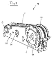
- Fig. 3 shows the middle universal slide 18 from FIG. 1 in a perspective view in isolation.
- 2 is the same carriage 18 shown in a side view, together with the rest of the cross wire provision device 10 in a partially sectioned illustration.
- the universal slide 18 shown in FIGS. 1-3 comprises one as a base or support structure of the universal slide 18 formed slide body 20.
- First on the slide body 20 is the drive roller 13 for the conveyor belt 8 with respect to the carriage body 20 rotatably mounted about a (virtual) axis of rotation 21, which to the combing wheel axis of rotation 11 is parallel and is referred to as the drive roller axis of rotation 21.
- the conveyor belt 8 is formed on its inner side with respect to the direction of rotation in the manner of a toothed belt and provided with a toothing, which with a corresponding toothing combs, which is formed on the outer peripheral surface of the driving roller 13. All in all the conveyor belt drive roller 13 thus serves as a drive pinion 13 for the type a conveyor belt 8.
- the conveyor belt drive roller 13 becomes coaxial with the drive roller axis of rotation 13 (and thus parallel to the drive wheel axis of rotation) arranged drive shaft 22 (conveyor belt drive shaft 22) driven to rotate about the drive roller axis of rotation 21.
- the conveyor belt drive shaft 22 is in two side walls 23 with respect to these in the longitudinal direction of the shaft immovable and rotatably mounted about the drive roller axis of rotation 21.
- the two side walls 23 are on one side laterally outside the through the Conveyor belts 7, 8, 9 formed cross wire feed path arranged, these side walls 23 as part of the stationary machine frame 3 of the cross wire provision device 10 are formed.
- a threaded spindle 24 provided with an external thread is provided, which extends parallel to the combing wheel axis of rotation 11 and around an axis to the combing wheel 11 parallel axis of rotation 25 (spindle axis 25) is rotatable.
- the threaded spindle 24 is in the two same side walls 23 with respect to these in the longitudinal direction of the spindle immovable and rotatably mounted about the spindle axis 25, in which also the Conveyor belt drive shaft 22 is mounted.
- the threaded spindle 24 passes through the slide body 20 and a lock nut 26, which is in a central region of the slide body 20 arranged and with this in the longitudinal direction of the spindle (i.e. in the direction parallel to Combing wheel axis of rotation 11) is coupled immovably.
- the lock nut is with one the internal thread corresponding to the external thread of the threaded spindle 24. It is designed as a divisible nut, being controlled automatically by a control signal can optionally be closed and opened again. In closed The lock nut 26 is in engagement with the thread of the threaded spindle 24.
- All universal slides 17, 18, 19 of the cross wire preparation device shown in FIGS. 1 and 2 10 are in terms of the conveyor belt drive and the drive for Purpose of moving the universal slide 17, 18, 19 transversely to the feed direction identical educated.
- the universal slides 17, 18, 19 are in relation to the combing wheel axis of rotation 11 arranged parallel to each other, the conveyor belt drive rollers 13 of the various universal slides 17, 18, 19 from a single common conveyor belt drive shaft 22 are driven. This makes synchronization simple the conveyor belts 7, 8, 9 of the various universal slides 17, 18, 19 reached.
- the lock nuts 26 of the various universal slides are also used 17, 18, 19 driven by a single common threaded spindle 24.
- the lock nuts 26 of the universal slide 17, 18, 19 become individual and independent controlled by each other to open or close them. This will give you the opportunity created, the individual universal slide 17, 18, 19 independently of one another transversely to the feed direction, although they are from a common threaded spindle 24th are driven.
- the cross wire preparation device 10 shown in FIGS. 1 and 2 is further with a Position measuring system provided, which for the automatic measurement of the position along the spindle axis 25 with respect to the stationary machine frame 3 of the cross wire preparation device 10 of each universal slide 17, 18, 19 is formed.
- the position measuring system measures the position of each universal slide 17, 18, 19 the basis of an induction resistance measurement and transmits the position data to one central machine control.
- the machine control then generates based on the measured Position data and depending on the length of the cross wires to be processed 1 and the desired position of these cross wires 1 with respect to the cross wire longitudinal direction Control signals for controlling the lock nuts 26 and the threaded spindle 24. These control signals are then sent to a drive motor (not shown).
- the universal car 17, 18, 19 shown in Fig. 1-3 are further with a combing wheel 5, 6 for combing out (separating) the cross wires 1 and / or a support wheel 27 for Support the cross wires 1 and / or a guide plate 15 for determining the position of the cross wires 1 in the cross wire longitudinal direction, the combing wheels 5, 6, Support wheels 27 and the guide plates 15 also together with the universal carriage 17, 18, 19, on which they are arranged, are displaceable transversely to the feed direction.
- the in Fig. 1 with respect to the feed direction arranged universal carriage 17, which in part is shown broken away, is on its right side with a provided the first combing wheel 5.
- FIG. 2 and 3 is on its left side with respect to FIG the feed direction with a second combing wheel 6 that with respect to a vertical mirror plane transverse to the feed direction mirror symmetrical, but otherwise essentially is identical to the first combing wheel 5.
- the one in Fig. 1 with respect to the feed direction of the universal carriage 19 arranged on the outside right is on its left Side with a support wheel 27 for supporting the cross wires 11 during their transport in the combing grooves 12 of the combing wheels 5, 6.
- the radius of the jockey wheel 27 corresponds approximately to the radial distance of the groove bottom of the combing grooves 12 from the Combing wheel axis of rotation 11.
- this universal carriage 19 On the right side is this universal carriage 19 with a vertical guide plate 15 provided on the right-hand longitudinal ends of the cross wires 1 acts to position them with respect to the cross wire longitudinal direction when the cross wires 1 on the conveyor belts 7, 8, 9 are conveyed along the guide plate 15 become.
- the automatic position measuring system is the device for automatic Moving the universal slide 17, 18, 19 transversely to the feed direction and Possibility of a plurality of different functional elements 5, 6, 15, 27 to be able to arrange the universal slide 17, 18, 19 ensures that the one shown in FIG and FIG. 2 shown cross wire provision device 10 for a multitude of different ones Cross wires 1 can be used and each quickly changes to cross wire dimensions can be customized.
- the universal slide 18 shown in FIGS. 1-3 is in the rearmost area of the slide body 20 the combing wheel 6 with respect to the slide body 20 about the combing wheel axis of rotation 11 rotatably mounted in the carriage body 20.
- the combing wheel 6 includes one first annular combing disc 28 (main combing disc 28), which with respect the carriage body 28 is rotatably mounted about the combing wheel axis of rotation 11.
- the main combing disk 28 is arranged coaxially with the axis of rotation 11 of the combing wheel Drive shaft 30 (combing wheel drive shaft 30) for rotation about its axis of rotation 11 driven.
- the comb-out wheel drive shaft 30 is in the two same side walls 23 of the stationary machine frame 3 with respect to these side walls 23 in the longitudinal direction of the shaft immovable and rotatable about the combing wheel axis of rotation 11, in which also the conveyor belt drive shaft 22 is mounted.
- the Main combing wheel 28 with the combing wheel drive shaft 30 is non-rotatable, but in Wavelength direction slidably coupled with respect to the combing wheel drive shaft 30.
- the combing wheel 6 further comprises a second annular combing disc 29 (Auxiliary combing disc 29), which is relative to the slide body 20 about the combing wheel axis of rotation 11 is rotatably mounted.
- the auxiliary combing disc 29 is parallel to the main combing disc 28 and arranged directly next to the same on the universal slide 18.
- a pinion-shaped pinion in the shape of a circular cylinder is attached to the auxiliary combing disk 29, which is arranged coaxially to the combing wheel axis of rotation 11.
- the pinion On its outer peripheral surface the pinion is provided with a toothing, which with the toothing of the conveyor belt 8 combs, which partially wraps around the pinion.
- the pinion serves as the drive pinion for the auxiliary combing disc 29 and at the same time as a deflection roller for the conveyor belt 8.
- the pinion of the auxiliary combing disk 29 is designed and arranged in such a way that that it is on the one hand by the conveyor belt 8 in the manner of a drive or transmission belt is driven to rotate about the combing wheel axis of rotation 11 and thereby the with the pinion auxiliary combing disc 29 for rotation about the combing wheel axis of rotation 11 drives.
- the pinion of the auxiliary combing disk 29 steers this Conveyor belt 8 so that its upper run on the desired path from the combing wheel 6 runs forward and down to the conveyor belt drive roller 13 runs to the To promote cross bars 1 on this track away from the combing wheel 6.
- the conveyor belt 8 has thus on the one hand the function of a conveyor belt, the cross bars 8 on it promotes upper strand.
- the annular auxiliary combing disc 29 is in its center from the combing wheel drive shaft 30 enforced.
- the auxiliary combing disk 29 is, however, in relation to the Combing wheel drive shaft 30 can be moved both in the longitudinal direction of the shaft and by the combing wheel axis of rotation 11 is rotatable. Overall, the arrangement of the auxiliary combing disc 29 with respect to the combing wheel drive shaft 30, the displaceability of the universal carriage 18 parallel to the combing wheel axis of rotation 11 is not impaired.
- each part-combing groove is designed such that its on the running direction of the combing wheel 6 (i.e. the running direction of the main and auxiliary combing disks 28, 29) front groove wall from the groove edge in the peripheral surface of the combing wheel at an angle of approximately 45 ° to a tangent to the edge of the groove in a straight line Line falls backwards to the front edge of the groove base.
- the groove bottom is in Formed essentially parallel to the circumferential line. It closes at its rear edge rear groove wall, which is essentially in the radial direction from the groove bottom to Extends peripheral surface.
- the main combing disc 28 and the auxiliary combing disc 29 driven synchronously with each other to rotate about the combing wheel axis of rotation 11, the main and auxiliary combing disks 28, 29 synchronized with one another in this way are that they are adjustable by one, but between two setting processes rotate constant phase angle offset from each other about the combing wheel axis of rotation 11.
- the phase angle or the offset between the main and auxiliary combing disks 28, 29 is set such that the groove cross sections of mutually corresponding partial combing grooves the main and auxiliary combing disks 28, 29 in to the combing wheel axis of rotation 11 in the parallel direction (i.e. in the longitudinal direction of the groove) partially or completely overlap.
- the total for the combing-out groove 12 of the combing-out wheel 6 effective groove cross-section is then smaller than the groove cross-sections in the main combing disc 28 and the auxiliary combing-out disc 29 formed part-combing grooves.
- the combing wheel 6 offers the Possibility of adapting the groove cross section or the groove thickness of the combing grooves 12 on cross wires 1 with different diameters.
- the cross wire preparation device 10 shown in FIGS. 1 and 2 is for processing of cross wires 1 are formed in a single path. That is, all cross wires can be provided in succession in the ready position in the cross wire holder 14.
- the cross wire provision device can also be used for parallel processing of Cross wires can be used in two or more lanes. Are for this purpose only to provide a sufficient number of universal slides and with appropriate Combing combing wheels, support wheels and side guide plates.
- the invention is a mesh welding system is specified, which a quick and easy adjustment of the grid welding system for Processing of cross wires with changed cross wire dimensions enabled.
Landscapes
- Engineering & Computer Science (AREA)
- Mechanical Engineering (AREA)
- Wire Processing (AREA)
Abstract
Description
Die Erfindung betrifft eine Anlage zum Herstellen von Drahtgittern aus einander kreuzenden und an den Kreuzungspunkten miteinander verschweissten Längs- und Querdrähten. The invention relates to a system for producing wire mesh from intersecting and at the crossing points welded longitudinal and transverse wires.
Bisher bekannte Gitterschweissanlagen zur Herstellung von Drahtgittern der eingangs genannten Art wie z.B. Baustahlmatten, Gitterstrukturen von Einkaufswagen, Lagergestellen u.ä., ermöglichen zwar die Herstellung von Drahtgittern mit einer hohen Produktionsrate, solange sämtliche Querdrähte jeweils im Wesentlichen identisch zueinander ausgebildet sind. Sobald jedoch mittels derselben Gitterschweissanlage Querdrähte mit unterschiedlichen Durchmessern und/oder unterschiedlicher Länge verarbeitet werden sollen, sind zeitaufwändige und komplizierte Umrüstungsarbeiten erforderlich, um die Gitterschweissanlage an die geänderten Querdrahtabmessungen anzupassen.Grid welding systems known hitherto for producing wire grids of the type mentioned at the beginning Type such as Structural steel mats, lattice structures of shopping trolleys, storage racks etc. enable the production of wire mesh with a high production rate, as long as all cross wires are essentially identical to each other are. However, as soon as using the same grid welding system cross wires with different Diameters and / or different lengths are to be processed Time-consuming and complicated retrofitting work required to the grid welding machine to adapt to the changed cross wire dimensions.
Aufgabe der Erfindung ist die Angabe einer Gitterschweissanlage, welche eine rasche und einfache Anpassung der Gitterschweissanlage zur Verarbeitung von Querdrähten mit geänderten Querdrahtabmessungen ermöglicht.The object of the invention is to provide a grid welding system which is quick and simple adaptation of the mesh welding system for processing cross wires with modified Cross wire dimensions enabled.
Die Lösung der Aufgabe ist durch die Merkmale des Anspruchs 1 definiert. Gemäss der Erfindung weist eine Gitterschweissanlage zum Herstellen von Drahtgittern aus einander kreuzenden und an den Kreuzungspunkten miteinander verschweissten Längs- und Querdrähten wenigstens eine Schweissmaschine zum Verschweissen eines Querdrahts mit einer Mehrzahl von Längsdrähten und eine Querdrahtzuführungseinrichtung zum Zuführen des Querdrahts an die Schweissmaschine auf. Die Querdrahtzuführungseinrichtung umfasst eine Querdrahtbereitstellungseinrichtung, die zur bundweisen Aufnahme von Querdrähten, zur Vereinzelung der Querdrähte und zur Bereitstellung der vereinzelten Querdrähte nacheinander in einer durch die Querdrahtbereitstellungseinrichtung definierten Bereitstellungsposition ausgebildet ist. Die Querdrahtbereitstellungseinrichtung weist ein stationäres Maschinengestell auf sowie wenigstens ein erstes Transportband, das zur Förderung der vereinzelten Querdrähte bezüglich dem Maschinengestell ausgebildet ist und eine Zuführrichtung definiert. Das erste Transportband ist als Teil einer ersten Montageeinheit ausgebildet, die als Ganzes quer zur Zuführrichtung verschiebbar ist. Die Querdrahtbereitstellungseinrichtung weist weiter erste Verschiebemittel zum Verschieben der ersten Montageeinheit quer zur Zuführrichtung auf.The solution to the problem is defined by the features of claim 1. According to the Invention has a mesh welding system for producing wire mesh from each other intersecting longitudinal and transverse wires welded together at the crossing points at least one welding machine for welding a cross wire a plurality of longitudinal wires and a cross wire feeder for feeding of the cross wire to the welding machine. The cross wire feeder includes a cross wire preparation device, which is used for the bundle pickup of cross wires, for separating the cross wires and for providing the separated cross wires one after the other in a one defined by the cross wire provision device Provision position is formed. The cross wire provision device has a stationary machine frame as well as at least a first conveyor belt for conveying the isolated cross wires are formed with respect to the machine frame and defines a feed direction. The first conveyor belt is part of a first assembly unit formed, which is displaceable as a whole transversely to the feed direction. The cross wire delivery facility also has first displacement means for displacing the first assembly unit transverse to the feed direction.
Im vorliegenden Zusammenhang wird die Richtung des Transports des Querdrahts vom Ort seiner Aufnahme durch die Zuführungseinrichtung bis zur Schweissmaschine als Zuführrichtung bezeichnet. Die Zuführrichtung ändert sich in der Regel während des Transports des Querdrahts durch die Zuführungseinrichtung. Sie hängt vom Ort des Querdrahts in der Zuführungseinrichtung ab. Im Bereich des Transportbands für den Querdrahttransport entspricht die Zuführrichtung der Förderrichtung des Querdrahts auf dem Transportband.In the present context, the direction of transport of the cross wire from the place its inclusion by the feed device up to the welding machine as the feed direction designated. The feed direction usually changes during transport of the cross wire through the feed device. It depends on the location of the cross wire in the Feeder from. Corresponds in the area of the conveyor belt for cross wire transport the feeding direction of the conveying direction of the cross wire on the conveyor belt.
Indem das erste Transportband als Teil einer als Ganzes quer zur Zuführrichtung verschiebbaren ersten Montageeinheit ausgebildet ist und die Querdrahtbereitstellungseinrichtung mit ersten Verschiebemitteln zum Verschieben der ersten Montageeinheit versehen ist, wird eine einfache und rasche Verstellung der Position des ersten Transportbands quer zur Förderrichtung ermöglicht. Dadurch kann die Querdrahtbereitstellungseinrichtung rasch und einfach an unterschiedliche Längen von Querdrähten angepasst werden, die auf dem ersten Transportband quer zu ihrer Längsrichtung gefördert werden.By having the first conveyor belt as part of a whole that can be moved transversely to the feed direction is formed first assembly unit and the cross wire preparation device provided with first displacement means for displacing the first assembly unit is a simple and quick adjustment of the position of the first conveyor belt enabled across the conveying direction. This enables the cross wire provision device can be quickly and easily adapted to different lengths of cross wires on the first conveyor belt are conveyed transversely to their longitudinal direction.
Gemäss einer bevorzugten Ausführungsart der Erfindung weist die Cluerdrahtbereitstellungseinrichtung weiter wenigstens ein zweites zur Förderung der vereinzelten Querdrähte ausgebildetes Transportband auf, das als Teil einer zweiten Montageeinheit ausgebildet ist, die als Ganzes quer zur Zuführrichtung und parallel zur ersten Montageeinheit verschiebbar ist, sowie zweite Verschiebemittel zum Verschieben der zweiten Montageeinheit quer zur Zuführrichtung und parallel zur ersten Montageeinheit. Die wenigstens zwei quer zur Zuführrichtung verstellbaren Transportbänder ermöglichen sowohl eine Anpassung der Querdrahtbereitstellungseinrichtung an unterschiedliche Querdrahtlängen als auch eine Änderung der Bereitstellungsposition, in welcher die Querdrähte bereit gestellt werden, in Bezug auf die Querdrahtlängsrichtung.According to a preferred embodiment of the invention, the Cluer wire provision device further at least a second to promote the isolated cross wires formed conveyor belt, which is designed as part of a second assembly unit, which can be moved as a whole transversely to the feed direction and parallel to the first assembly unit is, and second displacement means for displacing the second assembly unit transversely to the feed direction and parallel to the first assembly unit. The at least two across Conveyor belts adjustable in the feed direction allow both an adjustment of the Cross wire supply device to different cross wire lengths as well as one Change of the staging position in which the cross wires are stowed in Regarding the cross wire longitudinal direction.
Die ersten und zweiten Verschiebemittel können derart ausgebildet sein, dass sie ein vollständig voneinander unabhängiges Verschieben der ersten und zweiten Montageeinheit gewährleisten. Als Alternative dazu können die ersten und zweiten Verschiebemittel jedoch auch derart ausgebildet sein, dass die erste und zweite Montageeinheit lediglich teilweise unabhängig voneinander verschiebbar sind. Sie können z.B. derart ausgebildet sein, dass die erste und zweite Montageeinheit lediglich nacheinander in zwei voneinander unabhängige Verschiebepositionen verschiebbar sind oder bei einer gleichzeitigen Verschiebung lediglich parallel zueinander mit gleicher Verschiebegeschwindigkeit verschiebbar sind.The first and second displacement means can be designed such that they are completely mutually independent displacement of the first and second assembly unit guarantee. As an alternative, however, the first and second displacement means can also be designed such that the first and second assembly units are only partially can be moved independently of one another. You can e.g. be trained that the first and second assembly unit only one after the other in two mutually independent Moving positions are displaceable or with a simultaneous shift can only be moved parallel to each other at the same speed are.
Vorzugsweise weisen bei der Erfindungsvariante mit wenigstens zwei quer zur Zuführrichtung verschiebbaren Montageeinheiten die ersten und zweiten Verschiebemittel eine gemeinsame Gewindespindel auf, die sich parallel zur Verschieberichtung der ersten und zweiten Montageeinheiten erstreckt und die mit einem Aussengewinde versehen und zum Verschieben sowohl der ersten als auch der zweiten Montageeinheit ausgebildet ist. Die Verwendung einer gemeinsamen Gewindespindel zum Verschieben der ersten und der zweiten Montageeinheit erlaubt eine besonders einfache und kostengünstige Konstruktion der Verschiebemittel. Grundsätzlich sind jedoch auch andere geeignete Mittel zum Verschieben der Montageeinheiten verwendbar, so z.B. Linearantriebe auf der Basis von Zahnriemen, Umlaufketten oder Ritzel-Zahnstangen.Preferably, in the case of the variant of the invention with at least two crosswise to the feed direction sliding assembly units, the first and second displacement means a common Threaded spindle, which are parallel to the direction of displacement of the first and extends second assembly units and provided with an external thread and for Moving both the first and the second assembly unit is formed. The Use a common threaded spindle to move the first and the second assembly unit allows a particularly simple and inexpensive construction the displacement means. In principle, however, there are also other suitable means of moving of the assembly units can be used, e.g. Linear drives based on toothed belts, Circulating chains or pinion racks.
Im Falle von Verschiebemittel mit einer gemeinsamen Gewindespindel können die ersten Verschiebemittel eine erste Schlossmutter aufweisen, die mit der ersten Montageeinheit verbunden ist und ein Innengewinde aufweist, das wahlweise mit der Gewindespindel in Eingriff bringbar und wieder ausser Eingriff bringbar ist, um bei rotierender Gewindespindel die erste Montageeinheit wahlweise entweder nach Art eines Spindel-Mutter-Triebs quer zur Zuführrichtung zu verschieben oder bezüglich dem stationären Maschinengestell ruhen zu lassen. Analog können die zweiten Verschiebemittel eine zweite Schlossmutter aufweisen, die mit der zweiten Montageeinheit verbunden ist und ein Innengewinde aufweist, das wahlweise mit der Gewindespindel in Eingriff bringbar und wieder ausser Eingriff bringbar ist, um bei rotierender Gewindespindel die zweite Montageeinheit (17, 19) wahlweise entweder nach Art eines Spindel-Mutter-Triebs quer zur Zuführrichtung zu verschieben oder ruhen zu lassen. Dabei sind die beiden Schlossmuttern vorzugsweise unabhängig voneinander betätigbar, um ein voneinander im Wesentlichen unabhängiges Verschieben der beiden Montageeinheiten zu ermöglichen.In the case of displacement devices with a common threaded spindle, the first Moving means have a first lock nut that with the first assembly unit is connected and has an internal thread that optionally with the threaded spindle in Can be brought in and brought out of engagement again in order to rotate the threaded spindle the first assembly unit either crosswise in the manner of a spindle-nut drive to move to the feed direction or rest with respect to the stationary machine frame allow. Analogously, the second displacement means can have a second lock nut, which is connected to the second assembly unit and has an internal thread that can optionally be brought into engagement with the threaded spindle and brought out of engagement again is to either the second assembly unit (17, 19) with rotating threaded spindle either to move in the manner of a spindle-nut drive transversely to the feed direction or to let it rest. The two lock nuts are preferably independent of one another can be actuated in order to move the to enable both assembly units.
Vorteilhafterweise ist im Falle von wenigstens zwei quer zur Zuführrichtung verschiebbaren Montageeinheiten eine Transportbandantriebswelle vorgesehen, die im stationären Maschinengestell um eine erste quer zur Zuführrichtung verlaufende Drehachse drehbar und in Wellenlängsrichtung unverschiebbar gelagert ist, wobei diese Transportbandantriebswelle zum Antreiben sowohl des ersten Transportbands bezüglich der ersten Montageeinheit als auch des zweiten Transportbands bezüglich der zweiten Montageeinheit ausgebildet ist. Dadurch kann auf einfache Art eine Synchronisierung der Transportbänder der beiden Montageeinheiten gewährleistet werden. Um die Verschiebbarkeit der Montageeinheiten nicht zu beeinträchtigen, ist die Transportbandantriebswelle zwar drehfest, jedoch in Wellenlängsrichtung verschiebbar mit den Montageeinheiten gekoppelt.In the case of at least two that can be displaced transversely to the feed direction, it is advantageous Assembly units provided a conveyor belt drive shaft in the stationary machine frame rotatable about a first axis of rotation extending transversely to the feed direction and is immovably mounted in the longitudinal direction of the shaft, this conveyor belt drive shaft for driving both the first conveyor belt with respect to the first assembly unit as well as the second conveyor belt with respect to the second assembly unit is. This makes it easy to synchronize the conveyor belts of the two Assembly units are guaranteed. The movability of the assembly units not to be affected, the conveyor belt drive shaft is non-rotatable, but in Wavelength direction slidably coupled to the assembly units.
Vorteilhafterweise ist eine weitere Antriebswelle vorgesehen, die im stationären Maschinengestell um eine zweite, zur ersten Drehachse parallele Drehachse drehbar und in Wellenlängsrichtung unverschiebbar gelagert ist, wobei diese weitere Antriebswelle zum Antreiben sowohl einer ersten Funktionseinheit, die bezüglich der ersten Montageeinheit drehbar ist, als auch einer zweiten Funktionseinheit, die bezüglich der zweiten Montageeinheit drehbar ist, ausgebildet ist. Auf diese Art können weitere Funktionseinheiten auf den verschiedenen Montageeinheiten synchron zueinander angetrieben werden. Die weitere Antriebswelle ist wiederum zwar drehfest, jedoch in Wellenlängsrichtung verschiebbar mit den Montageeinheiten gekoppelt, um die Verschiebbarkeit der Montageeinheiten bezüglich dem stationären Maschinengestell zu gewährleisten.A further drive shaft is advantageously provided, which is in the stationary machine frame rotatable about a second axis of rotation parallel to the first axis of rotation and in the longitudinal direction of the shaft is immovably mounted, this further drive shaft for driving both a first functional unit related to the first assembly unit is rotatable, as well as a second functional unit, which is related to the second assembly unit is rotatable, is formed. In this way, additional functional units can be installed on the different assembly units are driven synchronously. The further one The drive shaft is in turn non-rotatable, but can also be displaced in the longitudinal direction of the shaft coupled to the assembly units to adjust the displaceability of the assembly units to ensure the stationary machine frame.
Eine von der weiteren Antriebswelle angetriebene Funktionseinheit kann z.B. ein mit Auskämmnuten (auch als Mitnehmernuten bezeichnet) versehenes Auskämmrad (auch als Mitnehmerrad oder Mitnehmerscheibe bezeichnet) sein, das um eine Drehachse drehbar an einer Montageeinheit angeordnet und zum Auskämmen eines einzelnen Querdrahts aus einer Mehrzahl von Querdrähten ausgebildet ist. Auskämmräder sind an sich bekannte Vorrichtungen, die zur Vereinzelung von Drähten aus einem Drahtbündel dienen. A functional unit driven by the further drive shaft can e.g. one with grooving grooves (also known as drive grooves) provided combing wheel (also as Driver wheel or drive plate), which is rotatable about an axis of rotation arranged on a mounting unit and for combing out a single transverse wire a plurality of cross wires is formed. Combing wheels are known per se Devices used for separating wires from a wire bundle.
Eine von der weiteren Antriebswelle angetrieben Funktionseinheit kann auch ein Stützrad sein, das um eine Drehachse drehbar an einer Montageeinheit angeordnet und zum Stützen eines insbesondere langen Querdrahts ausgebildet ist. Das Stützrad kann insbesondere parallel zu einem Auskämmrad angeordnet und synchron mit diesem angetrieben sein, um den Querdraht während dem Auskämmen zu stützen.A functional unit driven by the further drive shaft can also have a support wheel be rotatable about an axis of rotation on a mounting unit and for support a particularly long transverse wire is formed. The jockey wheel can in particular arranged parallel to a combing wheel and driven synchronously with it to support the cross wire during combing out.
Eine weitere vorteilhafte Variante der Erfindung zeichnet sich dadurch aus, dass an der Montageeinheit ein Führungsschild fest angebracht ist, der zum seitlichen Führen der Querdrähte während der Förderung der Querdrähte auf dem an der selben Montageeinheit angeordneten Transportband ausgebildet und angeordnet ist. Dies ermöglicht es den Führungsschild auf einfache Art zusammen mit der Montageeinheit zu verschieben, wenn der Führungsschild zum Zwecke einer Anpassung an eine geänderte Querdrahtlänge verstellt werden muss.Another advantageous variant of the invention is characterized in that the Mounting unit a guide plate is fixedly attached to the lateral guidance of the Cross wires during the conveyance of the cross wires on the same assembly unit arranged conveyor belt is formed and arranged. This enables the guide shield easy to move together with the assembly unit when the Guide plate adjusted for the purpose of adaptation to a changed cross wire length must become.
Gemäss einer weiteren bevorzugten Ausführungsart der Erfindung umfasst die Querdrahtbereitstellungseinrichtung weiter eine Positionsmessvorrichtung und eine Steuerungsvorrichtung. Die Positionsmessvorrichtung ist zum automatischen Messen der Position von sämtlichen Montageeinheiten bezüglich dem stationären Maschinengestell, zum Erzeugen von Positionssignalen entsprechend den gemessenen Positionen und zum Übertragen dieser Positionssignale an die Steuerungsvorrichtung ausgebildet. Die Steuerungsvorrichtung ist zum Empfangen der Positionssignale, zum Erzeugen von Steuerungssignalen in Abhängigkeit der Positionssignale und zum Übertragen der Steuerungssignale an die Verschiebemittel ausgebildet. Die Verschiebemittel ihrerseits sind zum Verschieben der Montageeinheiten in Abhängigkeit der von der Steuerungsvorrichtung empfangenen Steuerungssignale ausgebildet. Dadurch wird eine automatische Verschiebung der Montageeinheiten zum Anpassen der Querdrahtbereitstellungseinrichtung an geänderte Querdrahtabmessungen ermöglicht.According to a further preferred embodiment of the invention, the cross wire provision device comprises further a position measuring device and a control device. The position measuring device is for automatically measuring the position of all assembly units related to the stationary machine frame, for production of position signals corresponding to the measured positions and for the transmission of these Position signals formed on the control device. The control device is dependent on receiving the position signals and generating control signals the position signals and for transmitting the control signals to the displacement means educated. The shifting means in turn are for shifting the assembly units depending on the control signals received by the control device educated. This will automatically shift the assembly units to Adaptation of the cross wire provision device to changed cross wire dimensions allows.
Vorzugsweise ist die Positionsmessvorrichtung zum Messen der Positionen der Montageeinheiten auf der Basis von Induktionswiderstandsmessungen ausgebildet. Positionsmesssensoren auf der Basis von Induktionswiderstandsmessungen sind wenig störungs- und verschmutzungsanfällig und deshalb gut für den Einsatz in der rauhen Umgebung von Schweissmaschinen geeignet.The position measuring device is preferably for measuring the positions of the assembly units based on induction resistance measurements. Position measurement sensors on the basis of induction resistance measurements are little interference and susceptible to contamination and therefore good for use in the harsh environment of Suitable for welding machines.
Aus der nachfolgenden Detailbeschreibung und der Gesamtheit der Patentansprüche ergeben sich weitere vorteilhafte Ausführungsformen und Merkmalskombinationen der Erfindung.From the following detailed description and the entirety of the claims there are further advantageous embodiments and combinations of features of the invention.
Die zur Erläuterung des Ausführungsbeispiels verwendeten Zeichnungen zeigen:
- Fig. 1
- eine Querdrahtbereitstellungseinrichtung für eine Gitterschweissanlage gemäss einer bevorzugten Ausführungsart der Erfindung in einer vereinfachten, perspektivischen Teilansicht von schräg vorne;
- Fig. 2
- eine vereinfachte, schematische Querschnittansicht auf die Querdrahtbereitstellungseinrichtung aus Fig. 1;
- Fig. 3
- eine vereinfachte perspektivische Detailansicht auf einen Universalschlitten der Querdrahtbereitstellungseinrichtung aus Fig. 1.
- Fig. 1
- a cross wire preparation device for a mesh welding system according to a preferred embodiment of the invention in a simplified, perspective partial view obliquely from the front;
- Fig. 2
- a simplified, schematic cross-sectional view of the cross wire preparation device of Fig. 1;
- Fig. 3
- 2 shows a simplified perspective detailed view of a universal slide of the cross wire provision device from FIG. 1.
Grundsätzlich sind in den Figuren gleiche Teile mit gleichen Bezugszeichen versehen.In principle, the same parts are provided with the same reference symbols in the figures.
Die in Fig. 1 und 2 dargestellte Querdraht-Bereitstellungseinrichtung 10 ist Teil einer Gitterschweissanlage
zum Herstellen von Drahtgittern aus einander kreuzenden und an den
Kreuzungspunkten miteinander verschweissten Längs- und Querdrähten 1. Die Gitterschweissanlage
weist eine Schweissmaschine (nicht dargestellt) zum Verschweissen eines
Querdrahts 1 mit einer Mehrzahl von Längsdrähten und eine Querdrahtzuführungseinrichtung
zum Aufnehmen des Querdrahts 1 und zum Zuführen des Querdrahts 1 an die
Schweissmaschine auf. Die Querdrahtzuführungseinrichtung umfasst die in Fig. 1 und 2
dargestellte Querdrahtbereitstellungseinrichtung 10. Diese dient zur bundweisen Aufnahme
von Querdrähten 1, zur Vereinzelung der Querdrähte 1 sowie zur Bereitstellung der
vereinzelten Querdrähte 1 nacheinander in einer durch die Querdrahtbereitstellungseinrichtung
10 definierten Bereitstellungsposition. Die Querdrahtzuführungseinrichtung umfasst
weiter eine Querdraht-Transporteinrichtung (nicht dargestellt), welche die vereinzelten
Querdrähte 1 nacheinander in der Bereitstellungsposition abholt und von der Bereitstellungsposition
in eine vorgegebene Querdrahtsollposition in der Schweissmaschine
transportiert.The cross
Für den Betrieb der Gitterschweissanlage wird ein loser Bund aus einer Vielzahl von Querdrähten
1 auf eine Plattform 2 der Querdrahtbereitstellungseinrichtung 10 geladen, die auf
einem stationären Maschinengestell 3 der Querdrahtbereitstellungseinrichtung 10 angeordnet
ist. Die Oberseite der Plattform 2 ist nach Art einer geneigten Ebene ausgebildet
und angeordnet. Sie dient als Auflage- bzw. als Zuführfläche für die Querdrähte 1. Die
Querdrähte 1 werden mit ihrer Längsrichtung quer zu den Falllinien der geneigten Zuführfläche
(und somit horizontal) ausgerichtet, so dass sie aufgrund der Schwerkraft quer zu
ihrer Längsrichtung auf der Zuführfläche den Faillinien entlang nach unten (d.h. in Zuführrichtung)
rollen oder gleiten. Im Bereich des unteren (in Bezug auf die Zuführrichtung vorderen)
horizontalen Randes der Zuführfläche ist ein Rückweisorgan 4 (auch als Abstreiforgan
bezeichnet) über der Zuführfläche derart angeordnet, dass zwischen dem Rückweisorgan
4 und der Zuführfläche ein Kontrollspalt gebildet wird. Die Höhe dieses Kontrollspalts
ist derart bemessen, dass die Querdrähte 1 den Kontrollspalt lediglich als einlagige Drahtschicht
mit geringem Spiel passieren können. Querdrähte 1, die auf der untersten Querdrahtlage
aufliegen, werden vom Rückweisorgan 4 zurückgewiesen.A loose bundle of a large number of cross wires is used to operate the grid welding system
1 loaded onto a
Die Querdrahtbereitstellungseinrichtung 10 umfasst weiter mehrere Auskämmräder 5, 6,
von denen in der Darstellung der Fig. 1 zwei dargestellt sind. Die Auskämmräder 5, 6 sind
im Wesentlichen identisch zueinander ausgebildet und in Bezug auf die Zuführrichtung
unmittelbar vor dem Kontrollspalt parallel zueinander um eine gemeinsame (virtuelle)
Drehachse 11 drehbar angeordnet. Die als Auskämmrad-Drehachse 11 bezeichnete gemeinsame
Drehachse 11 der Auskämmräder 5, 6 verläuft parallel zur Ebene der Zuführfläche
und senkrecht zu den Falllinien dieser Ebene (d.h. insgesamt parallel zur Querdrahtlängsrichtung
und somit horizontal). Die Auskämmräder 5, 6 haben eine im Wesentlichen
kreiszylindermantelförmige Umfangsfläche und sind derart um die (virtuelle) Drehachse 11
drehbar, dass die Drehachse 11 mit der (geometrischen) Zylinderachse der Umfangsfläche
übereinstimmt. Die Auskämmräder 5, 6 sind bezüglich der Zuführfläche derart angeordnet,
dass der in Bezug auf die Zuführrichtung vordere Rand der geneigten Zuführfläche mit geringem
Spielabstand unmittelbar hinter einer im Wesentlichen vertikalen Partie der Umfangsflächen
der Auskämmräder 5, 6 liegt.The cross
In den Umfangsflächen der Auskämmräder 5, 6 sind in regelmässigen tangentialen Abständen
jeweils zueinander identische Nuten 12 (Auskämmnuten) ausgebildet, die sich
parallel zur Auskämmrad-Drehachse 11 erstrecken. Während des Betriebs der Gitterschweissanlage
rotieren die Auskämmräder 5, 6 synchron zueinander kontinuierlich um
die Auskämmrad-Drehachse 11, wobei die Auskämmräder 5, 6 derart zueinander synchronisiert
sind, dass einander entsprechende Auskämmnuten 12 der verschiedenen Auskämmräder
5, 6 je eine Serie (entsprechend der Anzahl der Auskämmräder 5, 6) von Auskämmnuten
12 bilden, die in zur Auskämmrad-Drehachse 11 paralleler Richtung zueinander
fluchten. Die Drehrichtung der Auskämmräder 5, 6 ist derart, dass die unmittelbar vor
dem vorderen Rand der Zuführflächen liegenden Partien der Umfangsflächen der Auskämmräder
5, 6 nach oben laufen. Dadurch wird bewirkt, dass jeder durch die Schwerkraft
auf der Zuführfläche nach vorne und unten geförderte Querdraht 1 unmittelbar nach dem
Passieren des Kontrollspalts jeweils einzeln in eine der Serien von zueinander fluchtenden
Auskämmnuten 12 gefördert wird. Die Dicke der Auskämmnuten 12 ist dem Durchmesser
der Querdrähte 1 derart angepasst, dass in jeder Auskämmnutserie nur ein Querdraht 1
aufgenommen wird. Die in den Auskämmnuten 12 aufgenommenen Querdrähte 1 werden
von den rotierenden Auskämmrädern 5, 6 nach oben mitgenommen und auf einer kreisförmigen
Bahn entsprechend dem radialen Abstand der Auskämmnuten 12 zur Auskämmrad-Drehachse
11 von der Zuführfläche weg gefördert. Die Auskämmräder 5, 6 bewirken
die eigentliche Vereinzelung der Querdrähte 1, denn die zuvor aneinanderliegenden Querdrähte
1 sind nun einzeln in den Auskämmnutserien 12 der Auskämmräder 5, 6 angeordnet,
wobei die Auskämmnutserien 12 in den Umfangsflächen der Auskämmräder 5, 6 in
tangentialer Richtung voneinander beabstandet sind.In the peripheral surfaces of the combing
Die Querdrahtbereitstellungseinrichtung 10 ist weiter mit mehreren Transportbändern 7, 8,
9 versehen, von denen in der Darstellung der Fig. 1 drei dargestellt sind. Jedes Transportband
7, 8, 9 ist nach Art eines endlos umlaufenden Förderbandes ausgebildet, dessen oberes
Trum während des Betriebs der Gitterschweissanlage die Querstäbe 1 von den Auskämmrädern
und der Zuführfläche weg nach vorne und unten fördert. Die Transportbänder
7, 8, 9 sind je identisch zueinander ausgebildet und in Bezug auf die Richtung der Auskämmrad-Drehachse
11 parallel zueinander angeordnet. Während des Betriebs laufen die
Transportbänder 7, 8, 9 je in einer zur Auskämmrad-Drehachse 11 senkrechten (und somit
vertikalen) Ebene endlos um. Jedes Transportband 7, 8, 9 ist auf seiner Aussenseite mit
nach aussen vorstehenden Nocken versehen, wobei die Bezeichnung "aussen" im vorliegenden
Zusammenhang in Bezug auf die Umlaufrichtung des Transportbandes 7, 8, 9 zu
verstehen ist. Die Nocken sind in regelmässigen Abständen über die gesamte Bandlänge
verteilt angeordnet. Während des Betriebs laufen alle Transportbänder 7, 8, 9 synchron
zueinander, wobei die Transportbänder 7, 8, 9 derart zueinander synchronisiert sind, dass
einander entsprechende Nocken der verschiedenen Transportbänder 7, 8, 9 je eine Serie
(entsprechend der Anzahl der Transportbänder) von Nocken bilden, die in Bezug auf die
Richtung der Auskämmrad-Drehachse 11 parallel zueinander angeordnet sind. In Bezug auf
die durch die Förderrichtung des Transportbandes 7, 8, 9 bestimmte Zuführrichtung wird
zwischen zwei benachbarten Nockenserien jeweils ein Transportfach definiert, das zur
Aufnahme eines Querdrahts 1 dient. Jeder der in den Nuten 12 der Auskämmräder 5, 6
aufgenommenen Querdrähte 1 wird durch die rotierenden Auskämmräder 5, 6 auf einer
kreisförmigen Bahn von der Zuführfläche auf die Transportbänder 7, 8, 9 gefördert und
dort einzeln je in einem Transportfach abgelegt, wobei die Länge des Transportwegs der
Querdrähte 1 von der Zuführfläche bis auf die Transportbänder ungefähr ein Drittel des der
kreisförmigen Bahn entsprechenden Kreisumfangs beträgt.The cross
Nachdem die Querdrähte einzeln in die Transportfächer abgelegt sind, werden sie durch
das obere Trum der Transportbänder 7, 8, 9 in einer durch dieses Trum definierten Zuführrichtung
schräg nach vorne und unten gefördert. Im Bereich der Transportband-Antriebsrollen
13, die zugleich als vorderste Umlenkrolle von jedem Transportband 7, 8, 9, ausgebildet
sind, werden die Querdrähte 1 nacheinander in einen stationären Querdrahthalter 14
der Querdrahtbereitstellungseinrichtung abgelegt bzw. abgeworfen. Dieser Querdrahthalter
14 umfasst eine Mehrzahl von identisch ausgebildeten plattenförmigen Halteteile, in
deren Oberseite je eine V-förmige Nut ausgebildet ist. Die Halteteile sind derart angeordnet,
dass ihre V-förmigen Nuten in zur Auskämmrad-Drehachse 11 paralleler Richtung zueinander
fluchten. Durch den Querdrahthalter 14 wird die Bereitstellungsposition der
Querdrähte 1 in Bezug auf die Richtungen senkrecht zur Querdrahtlängsrichtung definiert.After the cross wires are placed individually in the transport compartments, they are through
the upper run of the
Die Position der Querdrähte 1 in Querdrahtlängsrichtung (und somit die Bereitstellungsposition
der Querdrähte in Bezug auf die Querdrahtlängsrichtung) wird zunächst durch
zwei vertikale Führungsschilder 15 grob festgelegt, die in Bezug auf die Zuführrichtung
seitlich neben den beiden äussersten Transportbändern 9 der Querdrahtbereitstellungseinrichtung
angeordnet sind. Diese Führungsschilder 15 sind in Bezug auf die Zuführrichtung
von hinten nach vorne leicht konisch aufeinander zulaufend angeordnet und wirken
während des Transports der Querdrähte 1 auf den Transportbändern 7, 8, 9 in stossender
Funktion auf das ihnen zugewandte Längsende von jedem Querdraht 1 ein. Somit wird
jeder Querdraht 1 während des Transports auf den Transportbändern 7, 8, 9 durch die
Führungsschilder 15 von seinen beiden Längsenden her in Querdrahtlängsrichtung in die
gewünschte Längsposition geschoben, bevor er in den Querdrahthalter 14 abgeworfen
wird. Die Querdrahtbereitstellungseinrichtung 14 ist weiter mit zwei Stössel 16 versehen,
die in der Verlängerung der zueinander fluchtenden Nuten des Querdrahthalters 14 angeordnet
sind und in Querdrahtlängsrichtung in stossender Funktion auf je ein Längsende
eines im Querdrahthalter 14 aufgenommenen Querdrahts 1 einwirken, um eine Feinjustierung
der Bereitstellungsposition des Querdrahts 1 in Bezug auf die Querdrahtlängsrichtung
vorzunehmen.The position of the cross wires 1 in the longitudinal direction of the cross wire (and thus the ready position
of the cross wires in relation to the cross wire longitudinal direction) is first through
two
Mittels der Führungsschilder 15 und der Stössel 16 wird der Querdraht 1 mit einer zum
späteren Verschweissen mit den Längsdrähten ausreichenden Positionsgenauigkeit in
Bezug auf seine Längsrichtung in der Bereitstellungsposition bereit gestellt. Anschliessend
wird der Querdraht durch die Querdraht-Transporteinrichtung (nicht dargestellt) in der
Bereitstellungsposition ergriffen und unverschiebbar festgehalten, zwangsgeführt von der
Bereitstellungsposition zur Querdrahtsollposition in der Schweissmaschine transportiert
und dort positionsgenau abgesetzt. Dadurch wird der Querdraht derart positionsgenau in
seiner Sollposition in der Schweissmaschine abgesetzt, dass in der Schweissmaschine
kein Nachjustieren der Position des Querdrahts mehr erforderlich ist.By means of the
Um eine automatische Anpassung der Querdrahtbereitstellungseinrichtung auf Querdrähte
mit unterschiedlichen Drahtlängen zu ermöglichen, ist jedes Transportband 7, 8, 9 als Teil
einer Montageeinheit 17, 18, 19 ausgebildet, welche als Universalschlitten 17, 18, 19 bezeichnet
wird und als Ganzes parallel zur Auskämmrad-Drehachse 11 (d.h. quer zur Zuführrichtung)
bezüglich dem stationären Maschinengestell 3 der Querdrahtbereitstellungseinrichtung
10 verschiebbar ist. In Fig. 1 sind drei solche Universalschlitten 17, 18, 19 dargestellt,
einer davon in teilweise weggebrochener Darstellung. Fig. 3 zeigt den mittleren Universalschlitten
18 aus Fig. 1 in einer perspektivischen Ansicht in Alleinstellung. In Fig. 2 ist
derselbe Schlitten 18 in einer Ansicht von der Seite dargestellt, zusammen mit dem Rest
der Querdrahtbereitstellungseinrichtung 10 in teilweise geschnittener Darstellung.To automatically adapt the cross wire provision device to cross wires
To enable different wire lengths, each
Der in Fig. 1-3 dargestellte Universalschlitten 18 umfasst einen als Basis- oder Tragstruktur
des Universalschlittens 18 ausgebildeten Schlittenkörper 20. Zuvorderst am Schlittenkörper
20 ist die Antriebsrolle 13 für das Transportband 8 bezüglich dem Schlittenkörper
20 um eine (virtuelle) Drehachse 21 drehbar gelagert, die zur Auskämmrad-Drehachse 11
parallel ist und als Antriebsrollen-Drehachse 21 bezeichnet wird. Das Transportband 8 ist
auf seiner in Bezug auf die Umlaufrichtung inneren Seite nach Art eines Zahnriemens ausgebildet
und mit einer Zahnung versehen, welche mit einer entsprechenden Zahnung
kämmt, die auf der äusseren Umfangsfläche der Antriebsbsrolle 13 ausgebildet ist. Insgesamt
dient die Transportband-Antriebsrolle 13 somit als Antriebsritzel 13 für das nach Art
eines Zahnriemens ausgebildete Transportband 8.The
Die Transportband-Antriebsrolle 13 wird durch eine zur Antriebsrollen-Drehachse 13 koaxial
(und somit parallel zur Antriebsrad-Drehachse) angeordnete Antriebswelle 22 (Transportband-Antriebswelle
22) zur Drehung um die Antriebsrollen-Drehachse 21 angetrieben.
Die Transportband-Antriebswelle 22 ist in zwei Seitenwänden 23 bezüglich diesen in Wellenlängsrichtung
unverschiebbar und um die Antriebsrollen-Drehachse 21 drehbar gelagert.
Die beiden Seitenwände 23 sind je auf einer Seite seitlich ausserhalb der durch die
Transportbänder 7, 8, 9 gebildeten Querdraht-Zuführstrecke angeordnet, wobei diese Seitenwände
23 als Teil des stationären Maschinengestells 3 der Querdrahtbereitstellungseinrichtung
10 ausgebildet sind. Um die Verschiebbarkeit des Universalschlittens 18 parallel
zur Auskämmrad-Drehachse 11 zu gewährleisten, ist die Transportband-Antriebsrolle
13 mit der Transportband-Antriebswelle 22 zwar drehfest, jedoch in Wellenlängsrichtung
bezüglich der Transportband-Antriebswelle 22 verschiebbar gekoppelt.The conveyor
Für den Antrieb des Universalschlittens 18 zum Zwecke seiner Verschiebung quer zur Zuführrichtung
bezüglich dem stationären Maschinengestell 3 der Querdrahtbereitstellungseinrichtung
10 ist eine mit einem Aussengewinde versehene Gewindespindel 24 vorgesehen,
die sich parallel zur Auskämmrad-Drehachse 11 erstreckt und um eine zur Auskämmrad-Drehachse
11 parallele Drehachse 25 (Spindelachse 25) drehbar ist. Die Gewindespindel
24 ist in den beiden gleichen Seitenwänden 23 bezüglich diesen in Spindellängsrichtung
unverschiebbar und um die Spindelachse 25 drehbar gelagert, in denen auch die
Transportband-Antriebswelle 22 gelagert ist. Die Gewindespindel 24 durchsetzt den Schlittenkörper
20 und eine Schlossmutter 26, die in einem mittigen Bereich des Schlittenkörpers
20 angeordnet und mit diesem in Spindellängsrichtung (d.h. in Richtung parallel zur
Auskämmrad-Drehachse 11) unverschiebbar gekoppelt ist. Die Schlossmutter ist mit einem
dem Aussengewinde der Gewindespindel 24 entsprechenden Innengewinde versehen.
Sie ist als teilbare Mutter ausgebildet, wobei sie durch ein Steuerungssignal gesteuert automatisch
wahlweise geschlossen und wieder geöffnet werden kann. In geschlossenem
Zustand ist die Schlossmutter 26 mit dem Gewinde der Gewindespindel 24 in Eingriff. Sie
wirkt dann mit der Gewindespindel 24 zusammen als Spindel-Mutter-Trieb, welcher bei
einer Rotation der Gewindespindel 24 um die Spindelachse 25 die Schlossmutter 26 und
den mit dieser gekoppelten Universalschlitten 18 in Richtung der Spindelachse 25 (d.h. in
Spindellängsrichtung) linear verschiebt. In geöffnetem Zustand ist die Schlossmutter 26
ausser Eingriff mit der Gewindespindel 24, so dass in diesem Zustand eine Rotation der
Gewindespindel 24 keinen Einfluss auf die Position des Universalschlittens 18 in Spindellängsrichtung
hat.For driving the
Sämtliche Universalschlitten 17, 18, 19 der in Fig. 1 und 2 dargestellten Querdrahtbereitstellungseinrichtung
10 sind hinsichtlich dem Transportband-Antrieb und dem Antrieb zum
Zwecke des Verschiebens der Universalschlitten 17, 18, 19 quer zur Zuführrichtung identisch
ausgebildet. Die Universalschlitten 17, 18, 19 sind in Bezug auf Auskämmrad-Drehachse
11 parallel zueinander angeordnet, wobei die Transportband-Antriebsrollen 13 der
verschiedenen Universalschlitten 17, 18, 19 von einer einzigen gemeinsamen Transportband-Antriebswelle
22 angetrieben werden. Dadurch wird auf einfache Art eine Synchronisation
der Transportbänder 7, 8, 9 der verschiedenen Universalschlitten 17, 18, 19 erreicht.
Weiter werden auch die Schlossmuttern 26 der verschiedenen Universalschlitten
17, 18, 19 von einer einzigen gemeinsamen Gewindespindel 24 angetrieben. Hingegen
werden die Schlossmuttern 26 der Universalschlitten 17, 18, 19 individuell und unabhängig
voneinander gesteuert, um sie zu öffnen oder zu schliessen. Dadurch wird die Möglichkeit
geschaffen, die einzelnen Universalschlitten 17, 18, 19 unabhängig voneinander quer
zur Zuführrichtung zu verschieben, obwohl sie von einer gemeinsamen Gewindespindel 24
angetrieben werden.All
Die in Fig. 1 und 2 dargestellte Querdrahtbereitstellungseinrichtung 10 ist weiter mit einem
Positionsmesssystem versehen, welches zum automatischen Messen der Position
entlang der Spindelachse 25 bezüglich dem stationären Maschinengestell 3 der Querdrahtbereitstellungseinrichtung
10 von jedem Universalschlitten 17, 18, 19 ausgebildet ist.
Das Positionsmesssystem misst die Position von jedem Universalschlitten 17, 18, 19 auf
der Basis einer Induktionswiderstandsmessung und überträgt die Positionsdaten an eine
zentrale Maschinensteuerung. Die Maschinensteuerung erzeugt dann aufgrund der gemessenen
Positionsdaten und in Abhängigkeit der Länge der zu verarbeitenden Querdrähte 1
und der gewünschten Position dieser Querdrähte 1 in Bezug auf die Querdrahtlängsrichtung
Steuerungssignale zur Steuerung der Schlossmuttern 26 und der Gewindespindel 24.
Anschliessend werden diese Steuerungssignale an einen Antriebsmotor (nicht dargestellt)
für die Gewindespindel (24) und an Aktuatoren für die Schlossmuttern übertragen, um eine
automatische Betätigung der Gewindespindel 24 und der Schlossmuttern 26 derart zu
bewirken, dass die Universalschlitten 17, 18, 19 in Spindellängsrichtung auf die gewünschten
Positionen verschoben werden.The cross
Die in Fig. 1-3 dargestellten Universalwagen 17, 18, 19 sind weiter mit einem Auskämmrad
5, 6 zum Auskämmen (Vereinzeln) der Querdrähte 1 und/oder einem Stützrad 27 zum
Stützen der Querdrähte 1 und/oder einem Führungsschild 15 zum Festlegen der Position
der Querdrähte 1 in Querdrahtlängsrichtung versehen, wobei die Auskämmräder 5, 6, die
Stützräder 27 und die Führungsschilder 15 ebenfalls zusammen mit dem Universalwagen
17, 18, 19, an dem sie angeordnet sind, quer zur Zuführrichtung verschiebbar sind. Der in
Fig. 1 in Bezug auf die Zuführrichtung links angeordnete Universalwagen 17, der in teilweise
weggebrochener Darstellung dargestellt ist, ist auf seiner rechten Seite mit einem
ersten Auskämmrad 5 versehen. Der in Fig. 1 in der Mitte dargestellte Universalwagen 18,
der weiter auch in den Fig. 2 und 3 dargestellt ist, ist auf seiner linken Seite in Bezug auf
die Zuführrichtung mit einem zweiten Auskämmrad 6 versehen, dass in Bezug auf eine
vertikale Spiegelebene quer zur Zuführrichtung spiegelsymmetrisch, sonst aber im Wesentlichen
identisch zum ersten Auskämmrad 5 ausgebildet ist. Der in Fig. 1 in Bezug auf
die Zuführrichtung aussen rechts angeordnete Universalwagen 19 ist auf seiner linken
Seite mit einem Stützrad 27 zum Stützen der Querdrähte 11 während deren Transport in
den Auskämmnuten 12 der Auskämmräder 5, 6 versehen. Der Radius des Stützrads 27
entspricht ungefähr dem radialen Abstand des Nutbodens der Auskämmnuten 12 von der
Auskämmrad-Drehachse 11. Auf der rechten Seite ist dieser Universalwagen 19 mit einem
vertikalen Führungsschild 15 versehen, der auf die rechtsseitigen Längsenden der Querdrähte
1 einwirkt, um sie in Bezug auf die Querdrahtlängsrichtung zu positionieren, wenn
die Querdrähte 1 auf den Transportbändern 7, 8, 9 dem Führungsschild 15 entlang gefördert
werden.The
Insgesamt wird durch das automatische Positionsmesssystem, die Vorrichtung zum automatischen
Verschieben der Universalschlitten 17, 18, 19 quer zur Zuführrichtung und die
Möglichkeit, eine Mehrzahl von unterschiedlichen funktionellen Elementen 5, 6, 15, 27 an
den Universalschlitten 17, 18, 19 anordnen zu können, gewährleistet, dass die in Fig. 1
und 2 dargestellte Querdrahtbereitstellungseinrichtung 10 für eine Vielzahl von unterschiedlichen
Querdrähten 1 verwendbar ist und jeweils rasch an geänderte Querdrahtabmessungen
angepasst werden kann.Overall, the automatic position measuring system is the device for automatic
Moving the
Bei dem in Fig. 1-3 dargestellten Universalschlitten 18 ist im hintersten Bereich des Schlittenkörpers
20 das Auskämmrad 6 bezüglich dem Schlittenkörper 20 um die Auskämmrad-Drehachse
11 drehbar im Schlittenkörper 20 gelagert. Das Auskämmrad 6 umfasst eine
erste kreisringförmige Auskämmscheibe 28 (Hauptauskämmscheibe 28), die bezüglich
dem Schlittenkörper 28 um die Auskämmrad-Drehachse 11 drehbar gelagert ist. Die
Hauptauskämmscheibe 28 wird durch eine zur Auskämmrad-Drehachse 11 koaxial angeordnete
Antriebswelle 30 (Auskämmrad-Antriebswelle 30) zur Drehung um ihre Drehachse
11 angetrieben. Die Auskämmrad-Antriebswelle 30 ist in den beiden gleichen Seitenwänden
23 des stationären Maschinengestells 3 bezüglich diesen Seitenwänden 23 in Wellenlängsrichtung
unverschiebbar und um die Auskämmrad-Drehachse 11 drehbar gelagert, in
denen auch die Transportband-Antriebswelle 22 gelagert ist. Um die Verschiebbarkeit des
Universalschlittens 18 parallel zur Auskämmrad-Drehachse 11 zu gewährleisten, ist die
Hauptauskämmscheibe 28 mit der Auskämmrad-Antriebswelle 30 zwar drehfest, jedoch in
Wellenlängsrichtung bezüglich der Auskämmrad-Antriebswelle 30 verschiebbar gekoppelt.The
Das Auskämmrad 6 umfasst weiter eine zweite kreisringförmige Auskämmscheibe 29
(Hilfsauskämmscheibe 29), die bezüglich dem Schlittenkörper 20 um die Auskämmrad-Drehachse
11 drehbar gelagert ist. Die Hilfsauskämmscheibe 29 ist parallel zur Hauptauskämmscheibe
28 und unmittelbar neben derselben auf dem Universalschlitten 18 angeordnet.
An der Hilfsauskämmscheibe 29 ist ein kreiszylinderstumpfförmiges Ritzel angebracht,
das koaxial zur Auskämmrad-Drehachse 11 angeordnet ist. Auf seiner Aussenumfangsfläche
ist das Ritzel mit einer Zahnung versehen, welche mit der Zahnung des Transportbands
8 kämmt, welches das Ritzel teilweise umschlingt. Das Ritzel dient als Antriebsritzel
für die Hilfsauskämmscheibe 29 und gleichzeitig als Umlenkrolle für das Transportband
8. Das Ritzel der Hilfsauskämmscheibe 29 ist derart ausgebildet und angeordnet,
dass es einerseits durch das Transportband 8 nach Art eines Antriebs- oder Transmissionsriemens
zur Drehung um die Auskämmrad-Drehachse 11 angetrieben wird und dadurch die
mit dem Ritzel fest verbundene Hilfsauskämmscheibe 29 zur Drehung um die Auskämmrad-Drehachse
11 antreibt. Andererseits lenkt das Ritzel der Hilfsauskämmscheibe 29 das
Transportband 8 derart um, dass sein oberes Trum auf der gewünschten Bahn vom Auskämmrad
6 weg nach vorne und unten zur Transportband-Antriebsrolle 13 läuft, um die
Querstäbe 1 auf dieser Bahn vom Auskämmrad 6 weg zu fördern. Das Transportband 8 hat
somit zum Einen die Funktion eines Förderbandes, wobei es die Querstäbe 8 auf seinem
oberen Trum fördert. Zum Andern hat das von der Transportband-Antriebswelle 22 und der
Transportband-Antriebsrolle 13 angetriebene Transportband 8 aber auch die Funktion eines
Antriebsriemens, welcher die Hilfsauskämmscheibe 29 zur Drehung um die Auskämmrad-Drehachse
11 antreibt, wobei das obere Trum des Transportbands 8 als Zugtrum und
das untere Trum als Leertrum wirken.The combing
Die kreisringförmige Hilfsauskämmscheibe 29 wird zwar in ihrem Zentrum von der Auskämmrad-Antriebswelle
30 durchsetzt. Die Hilfsauskämmscheibe 29 ist aber bezüglich der
Auskämmrad-Antriebswelle 30 sowohl in Wellenlängsrichtung verschiebbar als auch um
die Auskämmrad-Drehachse 11 drehbar. Insgesamt wird durch die Anordnung der Hilfsauskämmscheibe
29 bezüglich der Auskämmrad-Antriebswelle 30 die Verschiebbarkeit
des Universalschlittens 18 parallel zur Auskämmrad-Drehachse 11 nicht beeinträchtigt.The annular
Die Hauptauskämmscheibe 28 und die Hilfsauskämmscheibe 29 sind im Bereich ihres
Aussenumfangs identisch zueinander ausgebildet und mit identischen Teil-Auskämmnuten
versehen. Im Querschnitt ist jede Teil-Auskämmnut derart ausgebildet, dass ihre in Bezug
auf die Laufrichtung des Auskämmrads 6 (d.h. der Laufrichtung der Haupt- und der Hilfsauskämmscheibe
28, 29) vordere Nutwand vom Nutrand in der Umfangsfläche des Auskämmrads
an unter einem Winkel von ungefähr 45 ° zu einer Tangente am Nutrand in gerader
Linie nach hinten zum vorderen Rand des Nutbodens abfällt. Der Nutboden ist im
Wesentlichen parallel zur Umfangslinie ausgebildet. An seinem hinteren Rand schliesst die
hintere Nutwand an, die sich im Wesentlichen in radialer Richtung zur vom Nutboden zur
Umfangsfläche erstreckt. The main combing
Während des Betriebs werden die Hauptauskämmscheibe 28 und die Hilfsauskämmscheibe
29 synchron zueinander zur Drehung um die Auskämmrad-Drehachse 11 angetrieben,
wobei die Haupt- und Hilfsauskämmscheibe 28, 29 derart zueinander synchronisiert
sind, dass sie um einen wählbar einstellbaren, zwischen zwei Einstellvorgängen aber
konstanten Phasenwinkel zueinander versetzt um die Auskämmrad-Drehachse 11 rotieren.
Der Phasenwinkel bzw. der Versatz zwischen der Haupt- und der Hilfsauskämmscheibe 28,
29 ist derart eingestellt, dass sich die Nutquerschnitte von einander entsprechenden Teil-Auskämmnuten
der Haupt- und der Hilfsauskämmscheibe 28, 29 in zur Auskämmrad-Drehachse
11 paralleler Richtung (d.h. in Nutlängsrichtung) teilweise oder vollständig
überlappen. Im Falle einer vollständigen Überlappung der Nutquerschnitte der in der
Haupt- und der Hilfsauskämmscheibe 28, 29 ausgebildeten Teil-Auskämmnuten entspricht
der für das Auskämmrad 6 insgesamt wirksame Nutquerschnitt der Auskämmnut 12 dem
vollen Nutquerschnitt einer einzigen Teil-Auskämmnut, wie sie in der Haupt- oder der Hilfsauskämmscheibe
28, 29 ausgebildet ist. Im Falle einer lediglich teilweisen Überlappung ist
jedoch nur derjenige Bereich des Nutquerschnitts der in der Hauptauskämmscheibe 28
ausgebildeten Teil-Auskämmnut zum Auskämmen eines Querdrahts 1 wirksam, der mit
dem Nutquerschnitt der entsprechenden in der Hilfsauskämmscheibe ausgebildeten Teil-Auskämmnut
überlappt. Der für die gesamte Auskämmnut 12 des Auskämmrads 6 insgesamt
wirksame Nutquerschnitt ist dann kleiner als die Nutquerschnitte der in der Hauptauskämmscheibe
28 und der Hilfsauskämmscheibe 29 ausgebildeten Teil-Auskämmnuten.
Durch eine wahlweise Einstellung der Phasenverschiebung zwischen der Haupt- und der
Hilfsauskämmscheibe 28, 29 kann somit der für die Auskämmnuten 12 des Auskämmrads
6 wirksame Nutquerschnitt bzw. die für die Auskämmnuten 12 des Auskämmrads 6
wirksame Nutdicke wahlweise eingestellt werden. Insgesamt bietet das Auskämmrad 6 die
Möglichkeit zur Anpassung des Nutquerschnitts bzw. der Nutdicke der Auskämmnuten 12
an Querdrähte 1 mit unterschiedlichen Durchmessern.During operation, the main combing
Die in Fig. 1 und 2 dargestellte Querdrahtbereitstellungseinrichtung 10 ist zur Verarbeitung
der Querdrähte 1 in einer einzigen Bahn ausgebildet. D.h., dass sämtliche Querdrähte
nacheinander in der Bereitstellungsposition im Querdrahthalter 14 bereit gestellt werden.
Die Querdrahtbereitstellungseinrichtung kann jedoch auch zur parallelen Verarbeitung von
Querdrähten in zwei oder noch mehr Bahnen verwendet werden. Für diesen Zweck sind
lediglich eine ausreichende Anzahl von Universalschlitten bereit zu stellen und mit entsprechenden
Auskämmrädern, Stützrädern und Seitenführungsschildern auszurüsten.The cross
Zusammenfassend ist festzustellen, dass durch die Erfindung eine Gitterschweissanlage angegeben wird, welche eine rasche und einfache Anpassung der Gitterschweissanlage zur Verarbeitung von Querdrähten mit geänderten Querdrahtabmessungen ermöglicht.In summary, it can be stated that the invention is a mesh welding system is specified, which a quick and easy adjustment of the grid welding system for Processing of cross wires with changed cross wire dimensions enabled.
Claims (11)
Priority Applications (1)
| Application Number | Priority Date | Filing Date | Title |
|---|---|---|---|
| EP02406080A EP1428596A1 (en) | 2002-12-09 | 2002-12-09 | System for making wire grids |
Applications Claiming Priority (1)
| Application Number | Priority Date | Filing Date | Title |
|---|---|---|---|
| EP02406080A EP1428596A1 (en) | 2002-12-09 | 2002-12-09 | System for making wire grids |
Publications (1)
| Publication Number | Publication Date |
|---|---|
| EP1428596A1 true EP1428596A1 (en) | 2004-06-16 |
Family
ID=32319728
Family Applications (1)
| Application Number | Title | Priority Date | Filing Date |
|---|---|---|---|
| EP02406080A Withdrawn EP1428596A1 (en) | 2002-12-09 | 2002-12-09 | System for making wire grids |
Country Status (1)
| Country | Link |
|---|---|
| EP (1) | EP1428596A1 (en) |
Cited By (3)
| Publication number | Priority date | Publication date | Assignee | Title |
|---|---|---|---|---|
| FR2895288A1 (en) * | 2005-12-22 | 2007-06-29 | Fabrication Rationalisee D Arm | Automated installation for the fabrication of the reinforcement structure for reinforced concrete, notably for use in economic activities such as building and civil engineering works |
| WO2009124520A1 (en) * | 2008-04-07 | 2009-10-15 | Bam Ag | Machine for producing uniaxial reinforcing steel mesh |
| CN113677453A (en) * | 2019-04-04 | 2021-11-19 | Mbk机械工程有限公司 | Cage welding machine and device for assembling same |
Citations (4)
| Publication number | Priority date | Publication date | Assignee | Title |
|---|---|---|---|---|
| FR2246477A1 (en) * | 1973-10-03 | 1975-05-02 | Herlin Bernard | Device to feed individual long bars for machining - uses oscillating arm with magnet or suction to lift rods |
| US4748309A (en) * | 1986-04-02 | 1988-05-31 | Evg Entwicklungs-U. Verwertungs-Gesellschaft M.B.H. | Multi-spot resistance-welding machine |
| EP0319950A1 (en) * | 1987-12-07 | 1989-06-14 | Emil Jäger GmbH & Co. KG | Crosswire feeding device for a grid-welding machine |
| DE10016036A1 (en) * | 2000-03-31 | 2001-10-18 | Tracto Technik | Tube bending machine with feeder for bar-shaped work pieces has stair-like feeder elements with toothed recesses, magazine, holder, tube transfer part, and measuring/monitoring device |
-
2002
- 2002-12-09 EP EP02406080A patent/EP1428596A1/en not_active Withdrawn
Patent Citations (4)
| Publication number | Priority date | Publication date | Assignee | Title |
|---|---|---|---|---|
| FR2246477A1 (en) * | 1973-10-03 | 1975-05-02 | Herlin Bernard | Device to feed individual long bars for machining - uses oscillating arm with magnet or suction to lift rods |
| US4748309A (en) * | 1986-04-02 | 1988-05-31 | Evg Entwicklungs-U. Verwertungs-Gesellschaft M.B.H. | Multi-spot resistance-welding machine |
| EP0319950A1 (en) * | 1987-12-07 | 1989-06-14 | Emil Jäger GmbH & Co. KG | Crosswire feeding device for a grid-welding machine |
| DE10016036A1 (en) * | 2000-03-31 | 2001-10-18 | Tracto Technik | Tube bending machine with feeder for bar-shaped work pieces has stair-like feeder elements with toothed recesses, magazine, holder, tube transfer part, and measuring/monitoring device |
Cited By (3)
| Publication number | Priority date | Publication date | Assignee | Title |
|---|---|---|---|---|
| FR2895288A1 (en) * | 2005-12-22 | 2007-06-29 | Fabrication Rationalisee D Arm | Automated installation for the fabrication of the reinforcement structure for reinforced concrete, notably for use in economic activities such as building and civil engineering works |
| WO2009124520A1 (en) * | 2008-04-07 | 2009-10-15 | Bam Ag | Machine for producing uniaxial reinforcing steel mesh |
| CN113677453A (en) * | 2019-04-04 | 2021-11-19 | Mbk机械工程有限公司 | Cage welding machine and device for assembling same |
Similar Documents
| Publication | Publication Date | Title |
|---|---|---|
| DE19522189C2 (en) | Grouping and buffering device | |
| DE2803223C2 (en) | ||
| DE2903461C2 (en) | ||
| EP1525811A1 (en) | Apparatus and method for transferring rod-like articles | |
| DE3641064A1 (en) | CONVEYING DEVICE FOR CONVEYING A DOUBLE STRAND SEPARATED ROD-SHAPED ARTICLE OF THE TOBACCO PROCESSING INDUSTRY | |
| DE1166674B (en) | Intermediate conveyor for adjacent rows of filters or other rod-shaped objects | |
| DE69718374T2 (en) | Method and device for the orderly removal of products that are supplied in a disorderly manner | |
| DE102013206138A1 (en) | Apparatus for completing a format set of products | |
| DE10146992A1 (en) | Transfer device and bowl drum as well as procedure for the transfer of hard filter elements | |
| DE4343477C1 (en) | Method for distribution of containers to multi-row conveyors | |
| EP3277605B1 (en) | Trough-type conveyor for transporting fish transversely to the longitudinal extent thereof in the transport direction, arrangement and method | |
| DE3729081A1 (en) | TASK FEEDER FOR LOADING PIECE PARTS ON A RECEIVING FEEDER | |
| DE10351068B4 (en) | staggering drum | |
| DE1285931B (en) | Intermediate conveyor for adjacent rows of filter rods, cigarettes or other rod-shaped objects | |
| EP3802382B1 (en) | Conveying apparatus and method of conveying tampon applicators | |
| DE3224330C2 (en) | ||
| EP1428596A1 (en) | System for making wire grids | |
| DE2035157C3 (en) | Device for the continuous displacement of initially n coaxially next to one another in rod-shaped articles of the tobacco processing industry lying one after the other transversely to the longitudinal direction | |
| EP0297201B1 (en) | Device for feeding lengths of longitudinal elements to a grid-welding machine | |
| DE4406089C2 (en) | Device for filling tablets or the like into tablet tubes | |
| WO2022008220A1 (en) | Transfer device, and method for transferring rod-shaped articles from a strand-forming device to a drum device | |
| EP1428594A2 (en) | Device for separating wires | |
| EP3613293B1 (en) | Sausage treatment device and method | |
| EP1428592A1 (en) | Device for separating wires | |
| DE2822823A1 (en) | DEVICE FOR CONVEYING CONTAINERS |
Legal Events
| Date | Code | Title | Description |
|---|---|---|---|
| PUAI | Public reference made under article 153(3) epc to a published international application that has entered the european phase |
Free format text: ORIGINAL CODE: 0009012 |
|
| AK | Designated contracting states |
Kind code of ref document: A1 Designated state(s): AT BE BG CH CY CZ DE DK EE ES FI FR GB GR IE IT LI LU MC NL PT SE SI SK TR |
|
| AX | Request for extension of the european patent |
Extension state: AL LT LV MK RO SI |
|
| 17P | Request for examination filed |
Effective date: 20040830 |
|
| AKX | Designation fees paid |
Designated state(s): AT BE BG CH CY CZ DE DK EE ES FI FR GB GR IE IT LI LU MC NL PT SE SI SK TR |
|
| 17Q | First examination report despatched |
Effective date: 20050401 |
|
| GRAP | Despatch of communication of intention to grant a patent |
Free format text: ORIGINAL CODE: EPIDOSNIGR1 |
|
| STAA | Information on the status of an ep patent application or granted ep patent |
Free format text: STATUS: THE APPLICATION IS DEEMED TO BE WITHDRAWN |
|
| 18D | Application deemed to be withdrawn |
Effective date: 20051122 |