EP0240840A2 - Dispositif pour produire des courants pour l'électrothérapie - Google Patents
Dispositif pour produire des courants pour l'électrothérapie Download PDFInfo
- Publication number
- EP0240840A2 EP0240840A2 EP87104383A EP87104383A EP0240840A2 EP 0240840 A2 EP0240840 A2 EP 0240840A2 EP 87104383 A EP87104383 A EP 87104383A EP 87104383 A EP87104383 A EP 87104383A EP 0240840 A2 EP0240840 A2 EP 0240840A2
- Authority
- EP
- European Patent Office
- Prior art keywords
- frequency
- voltage
- output
- counter
- digital
- Prior art date
- Legal status (The legal status is an assumption and is not a legal conclusion. Google has not performed a legal analysis and makes no representation as to the accuracy of the status listed.)
- Withdrawn
Links
- 238000001827 electrotherapy Methods 0.000 title 1
- 238000011156 evaluation Methods 0.000 claims abstract description 13
- 230000035559 beat frequency Effects 0.000 claims abstract description 6
- 238000000034 method Methods 0.000 claims description 8
- 108010076504 Protein Sorting Signals Proteins 0.000 claims description 3
- 230000000630 rising effect Effects 0.000 claims description 3
- 230000001225 therapeutic effect Effects 0.000 description 2
- 230000032683 aging Effects 0.000 description 1
- 238000010009 beating Methods 0.000 description 1
- 230000007423 decrease Effects 0.000 description 1
- 230000001419 dependent effect Effects 0.000 description 1
- 238000010586 diagram Methods 0.000 description 1
Images
Classifications
-
- A—HUMAN NECESSITIES
- A61—MEDICAL OR VETERINARY SCIENCE; HYGIENE
- A61N—ELECTROTHERAPY; MAGNETOTHERAPY; RADIATION THERAPY; ULTRASOUND THERAPY
- A61N1/00—Electrotherapy; Circuits therefor
- A61N1/18—Applying electric currents by contact electrodes
- A61N1/32—Applying electric currents by contact electrodes alternating or intermittent currents
Definitions
- Such devices are intended to generate currents with a relatively low, changeable frequency in a certain treatment area, such currents not to occur in other areas, but rather only currents of higher frequencies in the medium frequency range. This is achieved by introducing currents via current paths via two pairs of electrodes which intersect in a treatment area. Interfrequencies or beatings then occur in this area, which have the desired differential frequency. Outside the treatment area, the currents are ineffective by themselves because of the higher frequencies.
- the invention is accordingly based on the object of self-adjusting a device of the type mentioned at the outset, so that an exact setting of the differential frequency occurring in the treatment area and a constancy of the fundamental frequencies of both oscillators is ensured.
- the difference frequency occurring between the two oscillators is compared with a target frequency that can usually be changed in a controlled manner. If there is a deviation, the counter counts up or down.
- the counter reading is converted into a voltage by the digital-analog converter. With this voltage, the frequency of the voltage-controlled frequency-variable oscillator is changed until the difference frequency is equal to the target frequency.
- a pulse to be counted down occurs for each pulse to be counted up, so that the count and thus the voltage at the digital-to-analog converter remain unchangeable.
- Embodiments of the invention are the subject of the dependent claims.
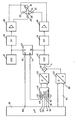
- the device for generating currents for the electrotherapeutic treatment contains a fixed-frequency oscillator 10 and a voltage-controlled frequency-variable oscillator 12.
- the oscillator 12 has a control input 14.
- the oscillators 10 and 12 deliver sequences of rectangular pulses. Therefore, a low-pass filter 16 is connected downstream of the oscillator 10.
- a low-pass filter 18 is connected downstream of the oscillator 12.
- the low-pass filters 16 and 18 generate essentially sinusoidal AC voltages from the square-wave pulses.
- the AC voltage from the low-pass filter 16 is amplified by means of a power amplifier 20.
- the amplified AC voltage is applied to a first pair of electrodes 22, 24, which define a current path 26 in a tissue to be treated.
- the alternating voltage is amplified by the low pass filter 18 by means of a power amplifier 28.
- the amplified AC voltage is applied to a second pair of electrodes 30, 32, which define a current path 34.
- the current path 34 crosses the current path 26 in a region 36. If the frequencies of the two oscillators 10 and 12 are different. then a beat occurs in this area 36: currents with the difference frequency are generated there and only there. For example, if the frequency of the oscillator 10 is 4 kHz and the frequency of the oscillator 12 is 4.1 kHz, then an alternating current with a frequency of 100 Hz occurs in the region 36.
- the beat frequency that is to say the difference between the frequencies of the two oscillators 10 and 12
- the frequencies of the oscillators 10 and 12 or one of these oscillators apply to be controlled so that the difference frequency corresponds to a predetermined target frequency.
- a microprocessor 38 is provided.
- the microprocessor 38 is used to control the sequence in a manner to be described and also generates the target frequency at an output 40.
- the output frequencies of the fixed-frequency oscillator 10 and the voltage-controlled frequency-variable oscillator 12 are connected to a frequency evaluation circuit 42.
- An up and down counting counter 46 is acted upon at an up input 48 with the desired frequency from the output 40 of the microprocessor 38.
- the difference frequency ⁇ f from the frequency evaluation circuit 42 is located at a downward input 50.
- the counter reading of the counter 46 is connected to a digital-to-analog converter 52.
- the voltage-controlled-frequency-variable oscillator 12 is controlled via the control input 14 by the analog output signal of the digital-to-analog converter 52.
- the meter reading therefore remains practically constant.
- the analog output signal of the digital-to-analog converter 52 then also remains constant.
- the capacity of the counter 46 is limited.
- the oscillator 12 should therefore be set at least approximately to the frequency of the fixed-frequency oscillator 10, so that the counter 46 and the digital-to-analog converter 52 need only control the frequency deviations.
- a reset input 54 of the counter 46 can be controlled continuously by a reset signal during an adjustment process, so that the counter reading is kept at zero.
- the adjustment process is initiated by the microprocessor 38, as will be described.
- the reset signal then appears at an output 56 of the microprocessor 38.
- the analog output signal of the digital-to-analog converter 52 is then also zero.
- a variable voltage from a voltage generator 60 can be superimposed on the analog output signal of the digital-analog converter 52 in a summing point 58.
- the voltage transmitter 60 contains a digital-to-analog converter 62. Rising or falling digital values can be connected to the digital input of the digital-to-analog converter 62. These digital values are supplied by the microprocessor 38 and appear at an output 64.
- the frequency evaluation circuit 42 outputs at an output 66 an output signal upon reversal of the sign of the difference frequency, ie when the frequency f2 of the oscillator 12 passes through the frequency f1 of the oscillator 10.
- This output signal from the frequency evaluation circuit 42 which is applied to an input 68 of the microprocessor 38 is switched, the voltage change of the voltage transmitter 60 is interrupted and the reset signal at the output 56 is switched off.
- the voltage transmitter 60 When the device is started up, the voltage transmitter 60 operates with a voltage which can be varied in an increasing manner.
- the analog output signal of the digital-to-analog converter 52 is kept at zero by the reset signal at the input 54 of the counter 40.
- the digital values at the output 64 of the microprocessor 38 increase.
- the analog output voltage of the digital-to-analog converter 62 rises accordingly.
- This output voltage also becomes effective via the summing point 58 at the control input 14 of the voltage-controlled frequency-variable oscillator 12.
- the frequency f2 of the oscillator 12 rises.
- the two oscillators 10 and 12 now have the same frequencies. At the same time, however, the reset signal is removed from input 54.
- the counter 46 begins to count. It counts up at the target frequency from input 40 of the microprocessor. This increases the counter reading and the output voltage of the digital-to-analog converter 52. This output voltage adds up in the summing point 58 to the now fixed output voltage of the digital-to-analog converter 62.
- the frequency f 2 of the oscillator 12 increases.
- a differential frequency ⁇ f thus occurs, which is counted down into the counter 46 as a feedback. In the stationary state, the differential frequency ⁇ f is equal to the target frequency at the output 40 of the microprocessor 38. This differential frequency ⁇ f then also appears as a beat frequency in the region 36.
- the capacity of the counter 46 can be exceeded during operation in that the frequencies of the two oscillators 10 and 12 diverge from one another due to any influences and that the difference between the difference frequency and the desired frequency cannot be established by the control loop. In this case, the counter 46 runs either full or empty. Then either an overflow signal occurs at an overflow output 70 or an empty count signal at an empty count output 72 of the counter 46 if the predetermined counter values are exceeded or fallen below.
- the overflow signal is connected to an input 74 of the microprocessor 38.
- the empty count signal is connected to an input 76 of the microprocessor 38.
- the voltage generator 60 and the reset signal at the output 56 can be controlled by the signals of the overflow output 70 and the empty counting output 72 in such a way that when a signal occurs at the overflow output 70, an adjustment process of the type described above with increasing variable voltage on the digital-to-analog converter 62 and when a signal occurs at the empty counting output 72, a variable voltage adjustment process is initiated.
Landscapes
- Health & Medical Sciences (AREA)
- Engineering & Computer Science (AREA)
- Biomedical Technology (AREA)
- Nuclear Medicine, Radiotherapy & Molecular Imaging (AREA)
- Radiology & Medical Imaging (AREA)
- Life Sciences & Earth Sciences (AREA)
- Animal Behavior & Ethology (AREA)
- General Health & Medical Sciences (AREA)
- Public Health (AREA)
- Veterinary Medicine (AREA)
- Stabilization Of Oscillater, Synchronisation, Frequency Synthesizers (AREA)
- Electrotherapy Devices (AREA)
Applications Claiming Priority (2)
| Application Number | Priority Date | Filing Date | Title |
|---|---|---|---|
| DE19863611537 DE3611537A1 (de) | 1986-04-05 | 1986-04-05 | Vorrichtung zur erzeugung von stroemen fuer die elektrotherapeutische behandlung |
| DE3611537 | 1986-04-05 |
Publications (2)
| Publication Number | Publication Date |
|---|---|
| EP0240840A2 true EP0240840A2 (fr) | 1987-10-14 |
| EP0240840A3 EP0240840A3 (fr) | 1988-06-29 |
Family
ID=6298074
Family Applications (1)
| Application Number | Title | Priority Date | Filing Date |
|---|---|---|---|
| EP87104383A Withdrawn EP0240840A3 (fr) | 1986-04-05 | 1987-03-25 | Dispositif pour produire des courants pour l'électrothérapie |
Country Status (2)
| Country | Link |
|---|---|
| EP (1) | EP0240840A3 (fr) |
| DE (1) | DE3611537A1 (fr) |
Family Cites Families (3)
| Publication number | Priority date | Publication date | Assignee | Title |
|---|---|---|---|---|
| DE2632700B2 (de) * | 1976-07-21 | 1978-10-05 | Gustav 8563 Schnaittach Doelker | Interferenzstrom-Therapiegerät |
| DE3147014A1 (de) * | 1981-11-27 | 1983-06-16 | Datron-Electronic Pichl & Schulte KG, 6109 Mühltal | Verfahren und geraet zur reizung erregbarer nerven- und muskelstrukturen u.dgl. |
| DE3335849A1 (de) * | 1983-10-03 | 1985-04-18 | Siemens AG, 1000 Berlin und 8000 München | Interferenzstromtherapiegeraet |
-
1986
- 1986-04-05 DE DE19863611537 patent/DE3611537A1/de not_active Withdrawn
-
1987
- 1987-03-25 EP EP87104383A patent/EP0240840A3/fr not_active Withdrawn
Also Published As
| Publication number | Publication date |
|---|---|
| EP0240840A3 (fr) | 1988-06-29 |
| DE3611537A1 (de) | 1987-10-08 |
Similar Documents
| Publication | Publication Date | Title |
|---|---|---|
| DE4009819C2 (de) | HF-Chirurgiegerät | |
| EP0709065B1 (fr) | Electrobistouri et méthode d'utilisation | |
| DE2721757C2 (de) | Interferenzstromtherapiegerät | |
| EP0329988B1 (fr) | Générateur de puissance haute fréquence | |
| DE3632134A1 (de) | Elektronische migraene-modulationseinrichtung und entsprechendes verfahren | |
| DE3731827C2 (de) | Einrichtung für Reizstrom-Therapiegeräte mit mehreren untereinander koordinierten Reizstromkreisen und Betriebsverfahren dafür | |
| DE3108563C2 (de) | Verfahren und Schaltungsanordnung zur elektrischen Versorgung einer Ozonerzeugereinheit | |
| DE2931638C2 (de) | Interferenzstromtherapiegerät | |
| DE3346744A1 (de) | Schaltungsanordnung zum ueberpruefen der lage von elektroden | |
| DE2143562C3 (de) | Interferenzstromtherapiegerät | |
| DE2851175A1 (de) | Frequenzsynthetisierer | |
| DE2159437C2 (de) | Schaltung zur Gewinnung zweier Wechselstrome gleicher Frequenz und moduherba rer Phase | |
| DE2249082B2 (de) | Dreieckspannungsgenerator | |
| EP0054654B1 (fr) | Appareil électro-médical | |
| DE3611537A1 (de) | Vorrichtung zur erzeugung von stroemen fuer die elektrotherapeutische behandlung | |
| EP0137936A1 (fr) | Appareil de thérapie à courant d'interférence | |
| DE3405630C1 (de) | Gerät zur Schmerzbehandlung durch elektrische Stimulation | |
| DE2338648A1 (de) | Schaltungsanordnung zur bestimmung des teilverhaeltnisses eines spannungsteilers | |
| EP0014316B1 (fr) | Appareil pour la thérapie par courants différentiels | |
| DE3541106A1 (de) | Vorrichtung zur erzeugung von stroemen fuer die elektrotherapeutische behandlung | |
| DE3813013A1 (de) | Reizstromgeraet | |
| DE2944157A1 (de) | Verfahren und einrichtung zum messen des pulses einer person | |
| DE669876C (de) | Einrichtung zur Behandlung im Kondensatorfelde kurzer elektrischer Wellen | |
| DE19801351B4 (de) | Niedrigfrequenztherapievorrichtung | |
| EP0035138A2 (fr) | Montage pour la génération d'un courant alternatif à basse fréquence en électrothérapie |
Legal Events
| Date | Code | Title | Description |
|---|---|---|---|
| PUAI | Public reference made under article 153(3) epc to a published international application that has entered the european phase |
Free format text: ORIGINAL CODE: 0009012 |
|
| AK | Designated contracting states |
Kind code of ref document: A2 Designated state(s): DE FR GB IT |
|
| PUAL | Search report despatched |
Free format text: ORIGINAL CODE: 0009013 |
|
| AK | Designated contracting states |
Kind code of ref document: A3 Designated state(s): DE FR GB IT |
|
| 17P | Request for examination filed |
Effective date: 19881224 |
|
| 17Q | First examination report despatched |
Effective date: 19910806 |
|
| STAA | Information on the status of an ep patent application or granted ep patent |
Free format text: STATUS: THE APPLICATION IS DEEMED TO BE WITHDRAWN |
|
| 18D | Application deemed to be withdrawn |
Effective date: 19920314 |
|
| RIN1 | Information on inventor provided before grant (corrected) |
Inventor name: STEFFEN, HARTWIG |