EP0240786A1 - Christbaumständer mit Schubverstellung - Google Patents
Christbaumständer mit Schubverstellung Download PDFInfo
- Publication number
- EP0240786A1 EP0240786A1 EP87103904A EP87103904A EP0240786A1 EP 0240786 A1 EP0240786 A1 EP 0240786A1 EP 87103904 A EP87103904 A EP 87103904A EP 87103904 A EP87103904 A EP 87103904A EP 0240786 A1 EP0240786 A1 EP 0240786A1
- Authority
- EP
- European Patent Office
- Prior art keywords
- tree
- sleeve
- foot
- stand
- foot cover
- Prior art date
- Legal status (The legal status is an assumption and is not a legal conclusion. Google has not performed a legal analysis and makes no representation as to the accuracy of the status listed.)
- Granted
Links
Images
Classifications
-
- A—HUMAN NECESSITIES
- A47—FURNITURE; DOMESTIC ARTICLES OR APPLIANCES; COFFEE MILLS; SPICE MILLS; SUCTION CLEANERS IN GENERAL
- A47G—HOUSEHOLD OR TABLE EQUIPMENT
- A47G33/00—Religious or ritual equipment in dwelling or for general use
- A47G33/04—Christmas trees
- A47G33/12—Christmas tree stands
-
- A—HUMAN NECESSITIES
- A47—FURNITURE; DOMESTIC ARTICLES OR APPLIANCES; COFFEE MILLS; SPICE MILLS; SUCTION CLEANERS IN GENERAL
- A47G—HOUSEHOLD OR TABLE EQUIPMENT
- A47G33/00—Religious or ritual equipment in dwelling or for general use
- A47G33/04—Christmas trees
- A47G33/12—Christmas tree stands
- A47G2033/1286—Christmas tree stands comprising watering means, e.g. a water reservoir
Definitions
- the invention relates to a device for setting up, aligning and holding Christmas trees.
- Tree stands are used to set up Christmas trees. Usually the tree trunk is pushed into the Christmas tree stand and fixed with screws at right angles to the tree axis in the stand. Tree stands are also known which allow the tree to be aligned via a ball joint, via clamp connections or via the adjustability of articulated foot supports.
- the devices listed here allow the correct alignment of the tree only with difficulty.
- the insertion of the tree into the stand and the attachment is often difficult and cumbersome.
- Most of the work is done in a stooped position or lying on the floor and with the help of another person.
- a Christmas tree stand is known (published application DE-OS 34 21 733), in which a fastening part screwed to the tree rests in an articulated socket and is frictionally clamped to the foot part via a tensioning band.
- the strap is tightened using a screw.
- the fastening part is also loosened using the screw. Accordingly, after inserting the fastening part into the socket of the foot part, cumbersome and cumbersome handling is required to align and fix the tree. Attention should also be drawn to the complex design of the device.
- DE-GM 77 25 342 describes a tree stand in which the tree holder is articulated in a foot container and is aligned and fixed by means of adjusting screws.
- the alignment of the tree is achieved by means of an opposing tension screw.
- the invention has for its object to provide a tree stand that allows installation and correct alignment in simple and easy handling.
- the sleeve which is connected to the tree trunk by means of a clamping screw connection and is inserted with the conically closed part, is fixed in the likewise conically shaped counterpart of the foot via a perforated plate.
- the plate lies on the surface of the foot cover. It is under a preselected contact pressure and can be moved against the frictional engagement between the two surfaces. Only the force exerted by hand on the tree causes an adjustment of the perforated plate centrally surrounding the sleeve and thus fixes the desired position of the tree.
- the foot of the tree stand is designed as a closed hollow body. It is filled with water in order to increase the stability of the device and to ensure that the tree is irrigated via inlet openings.
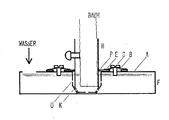
- a perforated plate P pressed on by spring elements E.
- the screws S which penetrate into the circumference of the foot cover A press the spring elements E against the perforated plate and foot cover A.
- the centrally in the perforated plate P bores B are selected in diameter so that a sufficiently large displaceability of the perforated plate P on the foot cover A is ensured.
- the sleeve H connected to the inserted tree trunk via a clamping screw is conical at the closed end. It is inserted through the perforated plate P into the conically shaped counterpart K. The sleeve H with the clamped tree is therefore opposite the foot F. fixed enough.
- the perforated plate P comprising the shaft of the sleeve H is shifted on the foot cover A until the desired vertical position of the tree is reached.
- inlet openings ⁇ are provided inside the foot container F and in the sleeve H.
Landscapes
- Cultivation Receptacles Or Flower-Pots, Or Pots For Seedlings (AREA)
- Mirrors, Picture Frames, Photograph Stands, And Related Fastening Devices (AREA)
Abstract
Description
- Die Erfindung bezieht sich auf eine Vorrichtung zum Aufstellen, Ausrichten und Festhalten von Weihnachtsbäumen.
- Zum Aufstellen von Weihnachtsbäumen werden die verschiedenartigsten Baumständer verwendet. Meist wird der Baumstamm in den Christbaumständer eingeschoben und mit rechtwinklig zur Baumachse im Ständer befindlichen Schrauben fixiert. Es sind auch Baumständer bekannt, die über ein Kugelgelenk, über Klemmverbindungen oder über die Verstellbarkeit von angelenkten Fußabstützungen das Ausrichten des Baumes gestatten.
- Die hier angeführten Vorrichtungen erlauben nur in beschwerlicher Weise das korrekte Ausrichten des Baumes. Auch ist das Einbringen des Baumes in den Ständer und die Befestigung oft schwierig und umständlich. Die Arbeiten sind meist in gebückter Haltung oder auf dem Fußboden liegend und unter Zuhilfenahme einer weiteren Person auszuführen.
- Es ist ein Christbaumständer bekannt (Offenlegungsschrift DE-OS 34 21 733), bei dem ein mit dem Baum verschraubtes Befestigungsteil in einer Gelenkpfanne ruht und über ein Spannband mit dem Fußteil reibschlüssig verklemmt wird. Zur Fixierung des Befestigungsteiles wird das Spannband mittels einer Schraube angespannt. Ebenso wird das Befestigungsteil über die Schraube gelöst. Dementsprechend ist nach dem Einsetzen des Befestigungsteiles in die Gelenkpfanne des Fußteiles eine umständliche und beschwerliche Handhabung zum Ausrichten und Feststellen des Baumes erforderlich. Hinzuweisen ist auch auf die aufwendige konstruktive Gestaltung der Vorrichtung.
- Die DE-GM 77 25 342 beschreibt einen Baumständer, bei dem der Baumhalter in einen Fußbehälter gelenkig eingesetzt ist und mittels Einstellschrauben ausgerichtet und fixiert wird. In der US-Patentschrift 15 84 011 wird das Ausrichten des Baumes über eine gegenläufige Spannschraube erreicht.
- Beide Vorrichtungen zeigen ebenfalls nicht die konstruktiven Merkmale, um die gewünschte Baumeinstellung in vorteilhafter Weise zu erreichen.
- Demgegenüber liegt der Erfindung die Aufgabe zugrunde, einen Baumständer zur Verfügung zu stellen, der in einfacher und unbeschwerlicher Handhabung das Aufstellen und korrekte Ausrichten erlaubt.
- Gemäß der Erfindung wird die über Klemmverschraubung mit dem Baumstamm verbundene und mit dem konusförmig abgeschlossenen Teil in das ebenfalls konisch geformte Gegenstück des Fußes eingesetzte Hülse über eine Lochplatte fixiert. Die Platte liegt auf der Oberfläche der Fußabdeckung. Sie steht unter einem vorgewählten Anpreßdruck und kann gegen den Reibungsschluß zwischen den beiden Flächen verschoben werden. Allein die von Hand auf den Baum ausgeübte Krafteinwirkung bewirkt eine Verstellung der die Hülse zentrisch umfassenden Lochplatte und fixiert damit die gewünschte Stellung des Baumes. Der Fuß des Baumständers ist als geschlossener Hohlkörper ausgebildet. Er wird mit Wasser gefüllt, um so die Standfestigkeit des Gerätes zu erhöhen und die Bewässerung des Baumes über Zulauföffnungen zu gewährleisten.
- Im folgenden wird die Erfindung anhand eines zeichnerisch dargestellten Ausführungsbeispieles näher erläutert.
- Auf der Fußabdeckung A befindet sich eine mittels Federelementen E aufgepreßte Lochplatte P. Diese umschließt zentrisch den Schaft der Hülse H. Die im Kreisumfang in die Fußabdeckung A eindringenden Schrauben S drücken die Federelemente E gegen die Lochplatte und Fußabdeckung A. Die zentrisch in in der Lochplatte P befindlichen Bohrungen B sind im Durchmesser so gewählt, daß eine genügend große Verschiebbarkeit der Lochplatte P auf der Fußabdeckung A gewährleistet ist. Die über eine Klemmschraube mit dem eingeschobenen Baumstamm verbundene Hülse H ist am geschlossenen Ende konisch ausgeführt. Sie wird durch die Lochplatte P in das ebenfalls konisch geformte Gegenstück K eingesetzt. Damit ist die Hülse H mit dem eingespannten Baum gegenüber dem Fuß F aus reichend fixiert. Durch Krafteinwirkung von Hand auf den Baum wird die den Schaft der Hülse H umfassende Lochplatte P auf der Fußabdeckung A soweit verschoben, bis die gewünschte vertikale Stellung des Baumes erreicht ist. Für die Bewässerung des Baumes sind Zulauföffnungen Ö innerhalb des Fußbehälters F und in der Hülse H vorgesehen.
Claims (1)
- Christbaumständer zum Aufstellen und Ausrichten von Weihnachtsbäumen, dadurch gekennzeichnet, daß eine den Baumstamm umfassende, mit diesem über Klemmverschraubung verbundene, am geschlossenen Ende konusförmig ausgebildete und in ein konisch geformtes Gegenstück (K) des Fußes (F) einsetzbare Hülse (H) dadurch fixiert wird, daß eine durch Feder- oder Klemmwirkung auf die Fußabdeckung (A) gepreßte und horizontal verschiebbare Lochplatte (P) die Hülse (H) umschließt.
Priority Applications (1)
| Application Number | Priority Date | Filing Date | Title |
|---|---|---|---|
| AT87103904T ATE57295T1 (de) | 1986-03-26 | 1987-03-17 | Christbaumstaender mit schubverstellung. |
Applications Claiming Priority (2)
| Application Number | Priority Date | Filing Date | Title |
|---|---|---|---|
| DE19863610282 DE3610282A1 (de) | 1986-03-26 | 1986-03-26 | Christbaumstaender |
| DE3610282 | 1986-03-26 |
Publications (2)
| Publication Number | Publication Date |
|---|---|
| EP0240786A1 true EP0240786A1 (de) | 1987-10-14 |
| EP0240786B1 EP0240786B1 (de) | 1990-10-10 |
Family
ID=6297365
Family Applications (1)
| Application Number | Title | Priority Date | Filing Date |
|---|---|---|---|
| EP87103904A Expired - Lifetime EP0240786B1 (de) | 1986-03-26 | 1987-03-17 | Christbaumständer mit Schubverstellung |
Country Status (3)
| Country | Link |
|---|---|
| EP (1) | EP0240786B1 (de) |
| AT (1) | ATE57295T1 (de) |
| DE (1) | DE3610282A1 (de) |
Cited By (5)
| Publication number | Priority date | Publication date | Assignee | Title |
|---|---|---|---|---|
| EP0850585A1 (de) | 1996-12-19 | 1998-07-01 | Société Crea | Ständer für Christbaum oder Kunstbusch |
| EP0868877A1 (de) | 1997-03-28 | 1998-10-07 | Société Crea | Dekorativer Ständer für Christbäume oder Kunstbüsche |
| GB2384697A (en) * | 2002-01-26 | 2003-08-06 | Joseph Noblett | Tree stand providing fluid |
| US20160374495A1 (en) * | 2011-12-01 | 2016-12-29 | Patent Innovations Llc | Christmas tree stand |
| US10182677B2 (en) | 2016-07-24 | 2019-01-22 | Patent Innovations Llc | Christmas tree stand |
Citations (5)
| Publication number | Priority date | Publication date | Assignee | Title |
|---|---|---|---|---|
| DE613012C (de) * | 1934-02-13 | 1935-05-10 | Paul H Mueller Dr Ing | Christbaumstaender |
| US2931604A (en) * | 1958-06-13 | 1960-04-05 | Billy D Weddle | Christmas tree holder |
| US3298643A (en) * | 1965-04-08 | 1967-01-17 | Albert J Taylor | Tree stand |
| DE7725342U1 (de) * | 1977-08-16 | 1977-12-01 | Eisenwerk Roedinghausen Gmbh & Co Kg, 5750 Menden | Baumstaender |
| DE2853148A1 (de) * | 1978-12-08 | 1980-06-26 | Heuermann Hans Ulrich Dipl Kfm | Verfahren und vorrichtung zum befestigen eines weihnachtsbaumes |
Family Cites Families (2)
| Publication number | Priority date | Publication date | Assignee | Title |
|---|---|---|---|---|
| US1584011A (en) * | 1925-05-21 | 1926-05-11 | Clifton Enoch | Tree support |
| DE3421733C2 (de) * | 1984-06-12 | 1987-02-19 | Georg 5828 Ennepetal Langer | Baumständer, insbesondere Weihnachtsbaumständer |
-
1986
- 1986-03-26 DE DE19863610282 patent/DE3610282A1/de active Granted
-
1987
- 1987-03-17 EP EP87103904A patent/EP0240786B1/de not_active Expired - Lifetime
- 1987-03-17 AT AT87103904T patent/ATE57295T1/de not_active IP Right Cessation
Patent Citations (5)
| Publication number | Priority date | Publication date | Assignee | Title |
|---|---|---|---|---|
| DE613012C (de) * | 1934-02-13 | 1935-05-10 | Paul H Mueller Dr Ing | Christbaumstaender |
| US2931604A (en) * | 1958-06-13 | 1960-04-05 | Billy D Weddle | Christmas tree holder |
| US3298643A (en) * | 1965-04-08 | 1967-01-17 | Albert J Taylor | Tree stand |
| DE7725342U1 (de) * | 1977-08-16 | 1977-12-01 | Eisenwerk Roedinghausen Gmbh & Co Kg, 5750 Menden | Baumstaender |
| DE2853148A1 (de) * | 1978-12-08 | 1980-06-26 | Heuermann Hans Ulrich Dipl Kfm | Verfahren und vorrichtung zum befestigen eines weihnachtsbaumes |
Cited By (8)
| Publication number | Priority date | Publication date | Assignee | Title |
|---|---|---|---|---|
| EP0850585A1 (de) | 1996-12-19 | 1998-07-01 | Société Crea | Ständer für Christbaum oder Kunstbusch |
| EP0868877A1 (de) | 1997-03-28 | 1998-10-07 | Société Crea | Dekorativer Ständer für Christbäume oder Kunstbüsche |
| GB2384697A (en) * | 2002-01-26 | 2003-08-06 | Joseph Noblett | Tree stand providing fluid |
| GB2384697B (en) * | 2002-01-26 | 2005-10-05 | Joseph Noblett | Improvements in and relating to tree stands |
| US20160374495A1 (en) * | 2011-12-01 | 2016-12-29 | Patent Innovations Llc | Christmas tree stand |
| US10575670B2 (en) * | 2011-12-01 | 2020-03-03 | Patent Innovations Llc | Christmas tree stand |
| US10182677B2 (en) | 2016-07-24 | 2019-01-22 | Patent Innovations Llc | Christmas tree stand |
| US10485369B2 (en) | 2016-07-24 | 2019-11-26 | Patent Innovations Llc | Christmas tree stand |
Also Published As
| Publication number | Publication date |
|---|---|
| DE3610282A1 (de) | 1987-10-01 |
| EP0240786B1 (de) | 1990-10-10 |
| ATE57295T1 (de) | 1990-10-15 |
| DE3610282C2 (de) | 1990-05-03 |
Similar Documents
| Publication | Publication Date | Title |
|---|---|---|
| EP0474976B1 (de) | Polyermerisationseinrichtung | |
| EP0240786B1 (de) | Christbaumständer mit Schubverstellung | |
| DE2630498A1 (de) | Einstellbarer halter | |
| EP0069060B1 (de) | Stellfuss für geodätische Instrumente | |
| DE9307092U1 (de) | Spannsystem | |
| DE8329821U1 (de) | Schnurhalter für ein Bügeleisen | |
| DE1477355A1 (de) | Werkzeughalter fuer Schneidwerkzeuge | |
| DE3601601A1 (de) | Christbaumstaender | |
| DE2530776A1 (de) | Schraubstock | |
| DE8608342U1 (de) | Christbaumständer | |
| DE2611168A1 (de) | Steckverbindung fuer zwei optische bauelemente | |
| DE1814145A1 (de) | Befestigung fuer Laeuferringe von Spinn- und Zwirnmaschinen | |
| DE8802938U1 (de) | Instrumentenhalterung für stereotaktische Gehirnoperationen | |
| DE2721110A1 (de) | Spannvorrichtung fuer auf einem maschinentisch o.dgl. aufzuspannende werkstuecke | |
| DE1224443B (de) | Artikulator | |
| DE3703415A1 (de) | Schraubstockartiges spanngeraet | |
| DE8601325U1 (de) | Christbaumständer | |
| DE3625926A1 (de) | Vorrichtung zum halten von zwei werkstuecken | |
| DE3400748C2 (de) | Gegen Umkippen gesicherter Weihnachtsbaumständer mit verstellbarem Aufnahmeteil | |
| DE561988C (de) | Kugelgelenk fuer Auslegerleuchten | |
| AT235661B (de) | Vorrichtung zur Anbringung eines Verbindungsstückes an einer Werkstoffstange | |
| CH167216A (de) | Klemmstativ für photographische Apparate, Fernrohre und dergleichen Instrumente. | |
| DE8703472U1 (de) | Schraubbock zum Unterstützen, Spannen und Richten von Werkstücken | |
| EP0307875A2 (de) | Munitionsgehäuse | |
| DE8236748U1 (de) | Spannvorrichtung fuer weihnachtsbaumstaender |
Legal Events
| Date | Code | Title | Description |
|---|---|---|---|
| PUAI | Public reference made under article 153(3) epc to a published international application that has entered the european phase |
Free format text: ORIGINAL CODE: 0009012 |
|
| AK | Designated contracting states |
Kind code of ref document: A1 Designated state(s): AT BE CH FR GB IT LI NL SE |
|
| 17P | Request for examination filed |
Effective date: 19880408 |
|
| 17Q | First examination report despatched |
Effective date: 19890605 |
|
| GRAA | (expected) grant |
Free format text: ORIGINAL CODE: 0009210 |
|
| AK | Designated contracting states |
Kind code of ref document: B1 Designated state(s): AT BE CH FR GB IT LI NL SE |
|
| REF | Corresponds to: |
Ref document number: 57295 Country of ref document: AT Date of ref document: 19901015 Kind code of ref document: T |
|
| ET | Fr: translation filed | ||
| GBT | Gb: translation of ep patent filed (gb section 77(6)(a)/1977) | ||
| ITF | It: translation for a ep patent filed | ||
| PLBE | No opposition filed within time limit |
Free format text: ORIGINAL CODE: 0009261 |
|
| STAA | Information on the status of an ep patent application or granted ep patent |
Free format text: STATUS: NO OPPOSITION FILED WITHIN TIME LIMIT |
|
| 26N | No opposition filed | ||
| ITTA | It: last paid annual fee | ||
| PGFP | Annual fee paid to national office [announced via postgrant information from national office to epo] |
Ref country code: NL Payment date: 19940331 Year of fee payment: 8 |
|
| EAL | Se: european patent in force in sweden |
Ref document number: 87103904.6 |
|
| PG25 | Lapsed in a contracting state [announced via postgrant information from national office to epo] |
Ref country code: NL Effective date: 19951001 |
|
| NLV4 | Nl: lapsed or anulled due to non-payment of the annual fee |
Effective date: 19951001 |
|
| PGFP | Annual fee paid to national office [announced via postgrant information from national office to epo] |
Ref country code: AT Payment date: 19960322 Year of fee payment: 10 |
|
| PGFP | Annual fee paid to national office [announced via postgrant information from national office to epo] |
Ref country code: BE Payment date: 19970217 Year of fee payment: 11 |
|
| PG25 | Lapsed in a contracting state [announced via postgrant information from national office to epo] |
Ref country code: AT Effective date: 19970317 |
|
| PG25 | Lapsed in a contracting state [announced via postgrant information from national office to epo] |
Ref country code: BE Free format text: LAPSE BECAUSE OF NON-PAYMENT OF DUE FEES Effective date: 19980331 |
|
| BERE | Be: lapsed |
Owner name: MEIDEL KARLHEINZ Effective date: 19980331 |
|
| PGFP | Annual fee paid to national office [announced via postgrant information from national office to epo] |
Ref country code: GB Payment date: 19990223 Year of fee payment: 13 |
|
| PGFP | Annual fee paid to national office [announced via postgrant information from national office to epo] |
Ref country code: SE Payment date: 20000224 Year of fee payment: 14 Ref country code: CH Payment date: 20000224 Year of fee payment: 14 |
|
| PGFP | Annual fee paid to national office [announced via postgrant information from national office to epo] |
Ref country code: FR Payment date: 20000225 Year of fee payment: 14 |
|
| PG25 | Lapsed in a contracting state [announced via postgrant information from national office to epo] |
Ref country code: GB Free format text: LAPSE BECAUSE OF NON-PAYMENT OF DUE FEES Effective date: 20000317 |
|
| GBPC | Gb: european patent ceased through non-payment of renewal fee |
Effective date: 20000317 |
|
| PG25 | Lapsed in a contracting state [announced via postgrant information from national office to epo] |
Ref country code: SE Free format text: LAPSE BECAUSE OF NON-PAYMENT OF DUE FEES Effective date: 20010318 |
|
| PG25 | Lapsed in a contracting state [announced via postgrant information from national office to epo] |
Ref country code: LI Free format text: LAPSE BECAUSE OF NON-PAYMENT OF DUE FEES Effective date: 20010331 Ref country code: CH Free format text: LAPSE BECAUSE OF NON-PAYMENT OF DUE FEES Effective date: 20010331 |
|
| EUG | Se: european patent has lapsed |
Ref document number: 87103904.6 |
|
| REG | Reference to a national code |
Ref country code: CH Ref legal event code: PL |
|
| PG25 | Lapsed in a contracting state [announced via postgrant information from national office to epo] |
Ref country code: FR Free format text: LAPSE BECAUSE OF NON-PAYMENT OF DUE FEES Effective date: 20011130 |
|
| REG | Reference to a national code |
Ref country code: FR Ref legal event code: ST |
|
| PG25 | Lapsed in a contracting state [announced via postgrant information from national office to epo] |
Ref country code: IT Free format text: LAPSE BECAUSE OF NON-PAYMENT OF DUE FEES;WARNING: LAPSES OF ITALIAN PATENTS WITH EFFECTIVE DATE BEFORE 2007 MAY HAVE OCCURRED AT ANY TIME BEFORE 2007. THE CORRECT EFFECTIVE DATE MAY BE DIFFERENT FROM THE ONE RECORDED. Effective date: 20050317 |