EP0240512B1 - Frequenzreferenzsystem und -methode - Google Patents
Frequenzreferenzsystem und -methode Download PDFInfo
- Publication number
- EP0240512B1 EP0240512B1 EP86905374A EP86905374A EP0240512B1 EP 0240512 B1 EP0240512 B1 EP 0240512B1 EP 86905374 A EP86905374 A EP 86905374A EP 86905374 A EP86905374 A EP 86905374A EP 0240512 B1 EP0240512 B1 EP 0240512B1
- Authority
- EP
- European Patent Office
- Prior art keywords
- radiation
- filter element
- frequency
- sources
- source
- Prior art date
- Legal status (The legal status is an assumption and is not a legal conclusion. Google has not performed a legal analysis and makes no representation as to the accuracy of the status listed.)
- Expired - Lifetime
Links
Images


Classifications
-
- H—ELECTRICITY
- H04—ELECTRIC COMMUNICATION TECHNIQUE
- H04B—TRANSMISSION
- H04B10/00—Transmission systems employing electromagnetic waves other than radio-waves, e.g. infrared, visible or ultraviolet light, or employing corpuscular radiation, e.g. quantum communication
- H04B10/50—Transmitters
- H04B10/501—Structural aspects
- H04B10/506—Multiwavelength transmitters
-
- H—ELECTRICITY
- H01—ELECTRIC ELEMENTS
- H01S—DEVICES USING THE PROCESS OF LIGHT AMPLIFICATION BY STIMULATED EMISSION OF RADIATION [LASER] TO AMPLIFY OR GENERATE LIGHT; DEVICES USING STIMULATED EMISSION OF ELECTROMAGNETIC RADIATION IN WAVE RANGES OTHER THAN OPTICAL
- H01S3/00—Lasers, i.e. devices using stimulated emission of electromagnetic radiation in the infrared, visible or ultraviolet wave range
- H01S3/23—Arrangements of two or more lasers not provided for in groups H01S3/02 - H01S3/22, e.g. tandem arrangements of separate active media
- H01S3/2383—Parallel arrangements
-
- H—ELECTRICITY
- H01—ELECTRIC ELEMENTS
- H01S—DEVICES USING THE PROCESS OF LIGHT AMPLIFICATION BY STIMULATED EMISSION OF RADIATION [LASER] TO AMPLIFY OR GENERATE LIGHT; DEVICES USING STIMULATED EMISSION OF ELECTROMAGNETIC RADIATION IN WAVE RANGES OTHER THAN OPTICAL
- H01S5/00—Semiconductor lasers
- H01S5/40—Arrangement of two or more semiconductor lasers, not provided for in groups H01S5/02 - H01S5/30
- H01S5/4025—Array arrangements, e.g. constituted by discrete laser diodes or laser bar
-
- H—ELECTRICITY
- H04—ELECTRIC COMMUNICATION TECHNIQUE
- H04B—TRANSMISSION
- H04B10/00—Transmission systems employing electromagnetic waves other than radio-waves, e.g. infrared, visible or ultraviolet light, or employing corpuscular radiation, e.g. quantum communication
- H04B10/50—Transmitters
- H04B10/572—Wavelength control
-
- H—ELECTRICITY
- H01—ELECTRIC ELEMENTS
- H01S—DEVICES USING THE PROCESS OF LIGHT AMPLIFICATION BY STIMULATED EMISSION OF RADIATION [LASER] TO AMPLIFY OR GENERATE LIGHT; DEVICES USING STIMULATED EMISSION OF ELECTROMAGNETIC RADIATION IN WAVE RANGES OTHER THAN OPTICAL
- H01S5/00—Semiconductor lasers
- H01S5/06—Arrangements for controlling the laser output parameters, e.g. by operating on the active medium
- H01S5/068—Stabilisation of laser output parameters
- H01S5/0683—Stabilisation of laser output parameters by monitoring the optical output parameters
- H01S5/0687—Stabilising the frequency of the laser
Definitions
- a method of referencing the frequencies of optical, microwave or radio frequency radiation from a plurality of first sources comprises guiding the radiation from each first source to a filter element having a replicated set of passbands spaced apart in frequency; monitoring radiation at each wavelength transmitted through the filter element; and controlling each of the first sources so that the radiation at each wavelength transmitted through the filter element is maintained substantially constant, the bandwidths of the radiation at each wavelength being smaller than the corresponding passbands of the filter element.
- a frequency referencing system comprises a plurality of first sources of optical, microwave or radio frequency radiation of different frequencies; a filter element having a replicated set of pass bands spaced apart in frequency on to which the radiation from each first source is incident; detection means for detecting the intensity of the radiation at each wavelength passing through the filter element and for providing output signals corresponding to each wavelength; and control means responsive to the output signals from the detection means to control each of the first sources so that the radiation at each wavelength transmitted through the filter element is maintained substantially constant, the bandwidths of the radiation at each wavelength being smaller than the corresponding passbands of the filter element.
- the invention provides a particularly simple way to lock the frequencies of the radiation from the sources relatively to one another. It is thus particularly suitable, when the radiation is optical radiation, in optical wideband networks as described above.
- the invention is also applicable to radiation at non-optical frequencies such as radio and microwaves.
- the monitoring step may comprise monitoring the intensity of the transmitted radiation.
- the bandwidths of the radiation are preferably offset from the central frequency of the corresponding passbands of the filter element and particularly conveniently they are positioned close to the edge of the corresponding passbands.
- the phase of the transmitted radiation may be monitored.
- the radiation bandwidth may be substantially centred on the corresponding passband and any change in the relative positions of the radiation frequency and the passband will result in a phase change in the transmitted beam the type of phase change differing with the direction of movement between the radiation frequency and passband.
- a further source comprises a reference source for generating a reference beam, the method further comprising guiding the radiation from the reference source to the filter element; monitoring transmitted radiation corresponding to the reference beam, and adjusting the filter element to maintain the transmission characteristic of the reference beam substantially constant.
- the system may include means for adjusting the filter element in response to output signals from the detection means corresponding to radiation from the reference source.
- the adjusting means may comprise means for physically moving or stressing the filter element such as a piezo transducer or a stepper motor or means for adjusting the temperature of the filter element or its support such as a Peltier cooler.
- the passbands of the filter element are substantially equally spaced apart in frequency.
- the filter element may be provided in the case of optical radiation by an optical waveguide loop or ring resonator which passes radiation having the fundamental frequency of the loop and also higher resonant frequencies but is most conveniently provided by a Fabry-Perot etalon.
- An etalon has a power transfer characteristic, usually at optical frequencies, which exhibits passbands at regular frequency intervals over a wide frequency range.
- the width of the passbands and their spacing are determined by the mechanical dimensions of the etalon and by the materials and coatings.
- Etalons may be made for example by using silica glass or air spaced devices. Integrated optic or fibre based devices may be used to achieve a similar effect.
- the spacing between passbands may range from for example 10's of MHz to several nm.
- the radiation from each source may be incident on different parts of the filter element. This enables the different radiation beams to be easily distinguished but requires the use of a corresponding plurality of detectors.
- radiation from the plurality of first sources is guided along the same path to the filter element, common detection means being provided to receive the radiation transmitted through the filter element, and the control means being arranged to impart respective identifiers to the radiation from each first source and to detect from the radiation passing through the filter element each identifier and the radiation corresponding to the identifier.
- the identifier may comprise a frequency or time code modulation.
- the sources will comprise lasers.
- each filter element is perfectly matched and in an optical communications network any mismatch could adversely affect switching or transmission performance.
- a communications network comprises a frequency reference system in accordance with the second aspect of the invention in which each first source of radiation comprises a reference source, multiplexing means for multiplexing the frequency referenced radiation from the reference sources and splitting means for splitting the multiplexed radiation into a plurality of subsidiary signals each of which is fed to a respective set of remote subsidiary sources of radiation; and subsidiary control means at each set of subsidiary sources for referencing the frequencies of the radiation from the subsidiary sources to one or more of the reference frequencies supplied from the splitting means.
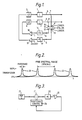
- Figure 1 illustrates two lasers 1, 2 driven by respective laser drivers 3, 4 which generate optical output signals having bandwidths centered on two different frequencies.
- the optical signals are guided along optical waveguides 5, 6, such as optical fibres, to respective fibre splitters 7, 8.
- a portion of the signal fed to each splitter 7, 8 is diverted to respective converging lenses 9, 10.
- Light from the lenses 9, 10 is focussed onto a Fabry-Perot etalon 11 at spaced apart locations.
- Optical radiation which passes through the etalon 11 is received by respective converging lenses 12, 13 and guided along optical fibres 14, 15 to respective photodiodes 16, 17.
- the photodiodes 16, 17 provide electrical outputs corresponding to the intensity of the light passing along the optical fibres 14, 15, the electrical outputs being fed to comparators 18, 19.
- the transmission characteristic of the etalon 11 is illustrated in Figure 2. This indicates that the etalon 11 has a plurality of passbands 20 substantially equally spaced in frequency. The spacing between the passbands 20 may range from 10's of MHz to several nm.
- the output signal from one of the lasers 1, 2 has a frequency falling within one of the passbands 20 it will be transmitted through the etalon 11, the intensity of the transmitted signal depending upon the frequency of the signal relative to the passband.
- the frequency of the optical signal is not exactly centered within the passband 20 so that any change in the intensity of the transmitted signal can be correlated easily with the direction of relative movement of the passband and the optical signal frequency.
- either the laser output is frequency modulated or the etalon frequency spacing is modulated and the photodiodes 16, 17 are followed by phase detectors.
- the frequency of the optical signals may be centred on corresponding passbands and in either case the interaction of the radiation and optical filter causes intensity changes in the received signal.
- the amplitude of the detected sub-carrier indicates the instantaneous difference between laser frequency and eta-Ion passband and the phase indicates the relative direction of movement.
- a desired output frequency for the optical signal from the laser 1 is set. This output frequency must fall within one of the passbands of the etalon 11 so that in use a signal will be received by the photodetector 17.
- a reference input to the comparator 19 is set so that the laser driver 3 controls the laser 1 to output an optical signal of the required frequency.
- the signal passing into the waveguide 15 will have a different intensity from its desired value.
- An electrical signal corresponding to the intensity of the incoming optical signal is generated by the photodiode 17 and is fed to the comparator 19. Since the comparator 19 will detect a difference between the signal from the photodiode 17 and the reference signal it will cause an appropriate electrical signal to be fed to the laser driver 3 to adjust the frequency of the optical signal generated by the laser 1. In this way, the output signal from the laser 1 is maintained at a substantially constant frequency.
- the laser 2 is similarly controlled but at a frequency corresponding to a different passband of the etalon 11. Since the spacing in frequency between the passbands of the etalon 11 is substantially fixed, the output signals from the lasers 1, 2 will also remain fixed relatively to one another despite changes in temperature or other affects.
- the etalon 11 itself is locked onto a more stable reference such as a He-Ne laser 21 or to a laser locked to an atomic reference.
- a more stable reference such as a He-Ne laser 21 or to a laser locked to an atomic reference.
- the optical output signal from the laser 21 is guided to the etalon 11 and the transmitted signal is received by a photodiode 22. This is fed to a comparator 23 whose output is fed to a positional control unit 24.
- the positional control unit could be either a piezo transducer of a stepper motor.
- a particularly attractive method of stabilising the etalon 11 is to place a crystal of LiNb0 3 in between the partially reflecting mirrors of the etalon. By controlling the electric field across the LiNb0 3 the optical pathlength may be varied. This approach would remove the need for mechanical movement of the etalon 11.
- each optical signal from the lasers is fed to a different part of the etalon 11. This requires that separate photodiodes are provided for each laser.
- An alternative example which simplifies the construction of the etalon and reduces the number of photodiodes required is illustrated in Figure 4.
- a plurality of lasers are provided (only two of which are shown in the drawing) whose output signals are fed to fibre splitters so that a portion of the output signals are guided to an optical combiner 25.
- the output of the optical combiner 25 is fed to a single converging lens 26, through the etalon 11 to a single lens 27 and from the lens 27 to a common photodiode 28.
- the electrical output from the photodiode 28 is fed to an electrical demultiplexer 29 having one output for each of the lasers.
- a modulator 30 is associated with each laser, the modulators 30 imparting a unique identification modulation to the output signals from the lasers.
- the modulation could be, for example either by frequency or time. If frequency is used then a unique frequency code is allocated to each laser, if time, then unique time slot or time code is allocated.
- the electrical demultiplexer 29 senses the identification modulation and provides electrical output signals relating to the intensity of the radiation corresponding to each identification modulation.
- Figure 5 illustrates a system for locking a laser to a reference laser based on the Figure 1 example and the modification of Figure 3.
- a reference laser 31 such as a He-Ne laser provides a reference optical signal which is fed to an etalon 32.
- the output signal from a laser 33 to be referenced is split so that part of the output signal is also fed to the etalon 32.
- Optical signals transmitted through the etalon 32 are split with the transmitted reference signal being fed to a photodiode 34 and to a photodiode 35 while the transmitted signal from the laser 33 is fed to a photodiode 36 and to the photodiode 35.
- the output signal from the photodiode 34 is fed via a buffer 37 and a control interface 38 to a positional control unit 39 similar to that shown in Figure 3.
- the output from the photodiode 36 is fed via a buffer 40 whose output is split with one portion being fed to a counter 41 and the other portion to a three position switch 42.
- the output of the photodiode 35 is fed to a filter 43, a comparator 44, and an electrical detector 45 whose output is also fed to the switch 42.
- the laser 33 is driven by a laser driver 46.
- the reference laser is shown co-sited with the semiconductor lasers being locked. These schemes would also allow the reference laser to be sited remotely from the locked lasers. Several sets of locked lasers might be sited at different locations remote from the reference laser in which case each set could have its own feeder from the reference laser and its own F-P etalon. In these circumstances, unless the etalons were perfectly matched, small differences in frequency would appear between the locations. In an optical communications network this could adversely affect switching or transmission performance. Figures 6 and 7 illustrate an arrangement to deal with this problem.
- the section in dashed lines in Figure 6 corresponds to the Figure 1 example with a majority of the locking system illustrated schematically at 47.
- the locked signals from the lasers two of which are indicated at 1, 2, with their identification modulations are fed to an optical combiner/split- ter 48 so that the optical signals are combined to form an optical frequency multiplex and then transmitted to a number of remote locations.
- an optical splitter 49 having one output for each laser of the set of lasers at that location.
- Each laser of the set of lasers is connected in an opto-electronic frequency control loop of the form illustrated in Figure 7.
- the multiplexed reference signals are fed from the splitter 49 along an optical fibre 50 to a photodiode 51, an electrical IF processor 52 and an electrical detector 53.
- the output from the detector 53 is fed to a buffer 54 whose output is fed to a laser driver 55 which controls the laser 56.
- the output signal from the laser 56 is split at 57 with a portion of the output signal being fed back to the photodiode 51.
- the loop is locked to any one of the reference signals in the incoming multiplexed signal via the path just described.
- An electrical beat frequency will appear at the output of the photodiode 51 and this is detected.
- the detected signal will contain the identification modulation corresponding to the reference frequency with which the laser 56 is locked and this identifier is fed to a code check circuit 58.
- This determines in conjunction with a control unit 59 if and how the local laser 56 should be returned.
- An appropriate correction signal is then added to the control signal in the buffer 54 to retune the laser 56 to a required channel. When this is completed, control continues via the direct loop path.
Landscapes
- Physics & Mathematics (AREA)
- Electromagnetism (AREA)
- Engineering & Computer Science (AREA)
- Computer Networks & Wireless Communication (AREA)
- Signal Processing (AREA)
- Optics & Photonics (AREA)
- Plasma & Fusion (AREA)
- Condensed Matter Physics & Semiconductors (AREA)
- General Physics & Mathematics (AREA)
- Optical Communication System (AREA)
- Semiconductor Lasers (AREA)
- Lasers (AREA)
Claims (14)
Priority Applications (1)
| Application Number | Priority Date | Filing Date | Title |
|---|---|---|---|
| AT86905374T ATE59503T1 (de) | 1985-09-16 | 1986-09-16 | Frequenzreferenzsystem und -methode. |
Applications Claiming Priority (2)
| Application Number | Priority Date | Filing Date | Title |
|---|---|---|---|
| GB858522821A GB8522821D0 (en) | 1985-09-16 | 1985-09-16 | Frequency referencing system |
| GB8522821 | 1985-09-16 |
Publications (2)
| Publication Number | Publication Date |
|---|---|
| EP0240512A1 EP0240512A1 (de) | 1987-10-14 |
| EP0240512B1 true EP0240512B1 (de) | 1990-12-27 |
Family
ID=10585221
Family Applications (1)
| Application Number | Title | Priority Date | Filing Date |
|---|---|---|---|
| EP86905374A Expired - Lifetime EP0240512B1 (de) | 1985-09-16 | 1986-09-16 | Frequenzreferenzsystem und -methode |
Country Status (8)
| Country | Link |
|---|---|
| US (1) | US4839614A (de) |
| EP (1) | EP0240512B1 (de) |
| JP (1) | JPS63500973A (de) |
| CA (1) | CA1251831A (de) |
| DE (1) | DE3676688D1 (de) |
| ES (1) | ES2002779A6 (de) |
| GB (1) | GB8522821D0 (de) |
| WO (1) | WO1987001874A1 (de) |
Families Citing this family (52)
| Publication number | Priority date | Publication date | Assignee | Title |
|---|---|---|---|---|
| JPH0681119B2 (ja) * | 1986-04-17 | 1994-10-12 | 日本電気株式会社 | 波長多重光伝送方式 |
| DE3854730T2 (de) * | 1987-06-09 | 1996-05-02 | At & T Corp | Optisches Übertragungssystem mit Konstanthalten einer Frequenzgruppe. |
| US5039984A (en) * | 1987-10-20 | 1991-08-13 | Telefind Corporation | Paging receiver with programmable areas of reception |
| JPH0239131A (ja) * | 1988-07-29 | 1990-02-08 | Hitachi Ltd | 周波数間隔安定化方法、光ヘテロダイン又は光ホモダイン通信方法 |
| AT393763B (de) * | 1989-03-21 | 1991-12-10 | Tabarelli Werner | Einrichtung zur konstanthaltung der luftwellenlaenge von laserlicht |
| US4979178A (en) * | 1989-06-20 | 1990-12-18 | The Boeing Company | Tunable narrow-linewidth semiconductor laser |
| US5003546A (en) * | 1989-08-31 | 1991-03-26 | At&T Bell Laboratories | Interferometric devices for reducing harmonic distortions in laser communication systems |
| US5023947A (en) * | 1989-11-01 | 1991-06-11 | At&T Bell Laboratories | Optical equalization receiver for lightwave communication systems |
| US5130998A (en) * | 1990-02-21 | 1992-07-14 | Mitsubiski Denki Kaubshiki Kaisha | Laser device with oscillation wavelength control |
| ATE130711T1 (de) * | 1990-09-11 | 1995-12-15 | Nederland Ptt | Optisches übertragungsnetzwerk mit frequenzverkopplungsmitteln. |
| DE4039955A1 (de) * | 1990-12-14 | 1992-06-17 | Zeiss Carl Fa | Anordnung mit zwei laserdioden zur erzeugung von licht mit zwei wellenlaengen |
| JP2734778B2 (ja) * | 1991-01-16 | 1998-04-02 | 日本電気株式会社 | 光増幅装置 |
| US5408349A (en) * | 1991-07-05 | 1995-04-18 | Hitachi, Ltd. | Optical frequency division multiplexing transmission system |
| JPH0576068U (ja) * | 1992-03-24 | 1993-10-15 | 横河電機株式会社 | 周波数安定化光源 |
| US5781334A (en) * | 1994-08-19 | 1998-07-14 | Leica Ag | Stabilized multi-frequency light source and method of generating synthetic light wavelengths |
| GB2293684B (en) * | 1994-09-27 | 1998-10-14 | Northern Telecom Ltd | An interfermetric multiplexer |
| JPH08316938A (ja) * | 1995-05-17 | 1996-11-29 | Canon Inc | 複数のチャンネルを多重して通信を行う光通信方法及び光通信システム |
| JPH0993194A (ja) * | 1995-09-27 | 1997-04-04 | Nec Corp | 波長安定回路 |
| GB2314617B (en) * | 1996-06-24 | 2000-08-23 | Graviner Ltd Kidde | High sensitivity gas detection |
| DE19625817A1 (de) * | 1996-06-28 | 1998-01-02 | Sel Alcatel Ag | Optische Sendeeinrichtung für ein hybrides Faser-Funk System |
| US5825792A (en) * | 1996-07-11 | 1998-10-20 | Northern Telecom Limited | Wavelength monitoring and control assembly for WDM optical transmission systems |
| JPH1075005A (ja) * | 1996-08-30 | 1998-03-17 | Ando Electric Co Ltd | 光周波数多重通信用光源装置 |
| US5978119A (en) * | 1997-02-18 | 1999-11-02 | Lucent Technologies Inc. | System and method for synchronizing an optical source and a router in a wavelength division multiplexed fiber optic network |
| US6061158A (en) * | 1997-11-04 | 2000-05-09 | Trw Inc. | High capacity wavelength division multiplexer |
| US5956356A (en) * | 1997-12-08 | 1999-09-21 | Lucent Technologies Inc. | Monitoring wavelength of laser devices |
| US6370169B1 (en) * | 1998-04-22 | 2002-04-09 | Nippon Telegraph & Telephone Corporation | Method and apparatus for controlling optical wavelength based on optical frequency pulling |
| JP2002525856A (ja) | 1998-09-11 | 2002-08-13 | ニュー・フォーカス・インコーポレイテッド | 波長可変レーザ |
| WO2000023764A1 (en) | 1998-10-16 | 2000-04-27 | New Focus, Inc. | Interferometer for optical wavelength monitoring |
| ATE359676T1 (de) * | 1999-06-30 | 2007-05-15 | Tno | Verfahren und kodier-/dekodier-anordnung zur bewertung der bildqualität von reproduzierten bilddaten |
| US6879619B1 (en) | 1999-07-27 | 2005-04-12 | Intel Corporation | Method and apparatus for filtering an optical beam |
| US6853654B2 (en) * | 1999-07-27 | 2005-02-08 | Intel Corporation | Tunable external cavity laser |
| WO2001011739A1 (en) | 1999-08-10 | 2001-02-15 | Coretek, Inc. | Single etalon optical wavelength reference device |
| US6847661B2 (en) * | 1999-09-20 | 2005-01-25 | Iolon, Inc. | Tunable laser with microactuator |
| US6856632B1 (en) * | 1999-09-20 | 2005-02-15 | Iolon, Inc. | Widely tunable laser |
| DE19954036A1 (de) * | 1999-10-29 | 2001-05-10 | Siemens Ag | Verfahren und Anordnung zur Wellenlängenstabilisierung von Licht |
| US7209498B1 (en) | 2000-05-04 | 2007-04-24 | Intel Corporation | Method and apparatus for tuning a laser |
| US6631019B1 (en) | 2000-07-05 | 2003-10-07 | Sri International | Reconfigurable multichannel transmitter for dense wavelength division multiplexing (DWDM) optical communication |
| US7120176B2 (en) * | 2000-07-27 | 2006-10-10 | Intel Corporation | Wavelength reference apparatus and method |
| US7315697B2 (en) * | 2000-09-26 | 2008-01-01 | Celight, Inc. | Light source for generating an output signal having spaced apart frequencies |
| FR2820246B1 (fr) * | 2001-01-26 | 2005-06-17 | Algety Telecom | Dispositif et procede d'asservissement de sources optiques |
| US6658031B2 (en) | 2001-07-06 | 2003-12-02 | Intel Corporation | Laser apparatus with active thermal tuning of external cavity |
| US6804278B2 (en) | 2001-07-06 | 2004-10-12 | Intel Corporation | Evaluation and adjustment of laser losses according to voltage across gain medium |
| US6822979B2 (en) | 2001-07-06 | 2004-11-23 | Intel Corporation | External cavity laser with continuous tuning of grid generator |
| US6901088B2 (en) * | 2001-07-06 | 2005-05-31 | Intel Corporation | External cavity laser apparatus with orthogonal tuning of laser wavelength and cavity optical pathlength |
| US6724797B2 (en) | 2001-07-06 | 2004-04-20 | Intel Corporation | External cavity laser with selective thermal control |
| US7230959B2 (en) | 2002-02-22 | 2007-06-12 | Intel Corporation | Tunable laser with magnetically coupled filter |
| WO2006063473A1 (en) * | 2004-12-16 | 2006-06-22 | Vectronix Ag | Non temperature stabilized pulsed laser diode and all fibre power amplifier |
| WO2007007848A1 (ja) * | 2005-07-13 | 2007-01-18 | Nec Corporation | 外部共振器型波長可変レーザ及びその実装方法 |
| US7583711B2 (en) * | 2006-03-17 | 2009-09-01 | Lockheed Martin Coherent Technologies, Inc. | Apparatus and method for stabilizing the frequency of lasers |
| GB2445956B (en) * | 2007-01-26 | 2009-12-02 | Valtion Teknillinen | A spectrometer and a method for controlling the spectrometer |
| CN101674135A (zh) * | 2008-09-09 | 2010-03-17 | 华为技术有限公司 | 滤波锁定方法、装置 |
| JP5831206B2 (ja) * | 2011-12-21 | 2015-12-09 | 富士通株式会社 | 光スイッチ素子、光復調器、光復調方法 |
Family Cites Families (14)
| Publication number | Priority date | Publication date | Assignee | Title |
|---|---|---|---|---|
| US3967211A (en) * | 1974-01-17 | 1976-06-29 | Jersey Nuclear-Avco Isotopes, Inc. | Laser wavelength stabilization |
| US4081765A (en) * | 1976-06-03 | 1978-03-28 | Coherent, Inc. | Method and apparatus for providing a calibrated scan for a scanning laser |
| US4092070A (en) * | 1976-10-26 | 1978-05-30 | Lansing Research Corporation | Tuning of etalons in spectroscopic apparatus |
| US4096448A (en) * | 1977-01-12 | 1978-06-20 | Rockwell International Corporation | Phase-locking of independent laser oscillators |
| US4150342A (en) * | 1977-07-05 | 1979-04-17 | Coherent, Inc. | Method and apparatus for automatically reacquiring a predetermined output radiation frequency in a tunable laser system despite momentary perturbations of laser oscillation |
| EP0001714B1 (de) * | 1977-10-26 | 1984-03-21 | The Post Office | Steuerapparat für eine Halbleiter-Laservorrichtung |
| JPS59140B2 (ja) * | 1979-01-13 | 1984-01-05 | 日本電信電話株式会社 | 半導体レ−ザ装置 |
| GB2043240A (en) * | 1979-03-01 | 1980-10-01 | Post Office | Improvements in or relating to the switching of signals |
| US4410992A (en) * | 1980-03-26 | 1983-10-18 | Laser Science, Inc. | Generation of pulsed laser radiation at a finely controlled frequency by transient regerative amplification |
| EP0108562A1 (de) * | 1982-11-05 | 1984-05-16 | British Telecommunications | Verfahren und Vorrichtung zum Steuern von Lasern |
| US4672618A (en) * | 1983-03-07 | 1987-06-09 | Beckman Instruments, Inc. | Laser stabilization servo system |
| US4592043A (en) * | 1983-07-08 | 1986-05-27 | At&T Bell Laboratories | Wavelength division multiplexing optical communications systems |
| US4771431A (en) * | 1985-08-30 | 1988-09-13 | Konishiroku Photo Industry Co., Ltd. | Semiconductor laser drive |
| US4719635A (en) * | 1986-02-10 | 1988-01-12 | Rockwell International Corporation | Frequency and phase locking method for laser array |
-
1985
- 1985-09-16 GB GB858522821A patent/GB8522821D0/en active Pending
-
1986
- 1986-09-15 CA CA000518227A patent/CA1251831A/en not_active Expired
- 1986-09-16 DE DE8686905374T patent/DE3676688D1/de not_active Expired - Lifetime
- 1986-09-16 WO PCT/GB1986/000553 patent/WO1987001874A1/en not_active Ceased
- 1986-09-16 ES ES8602290A patent/ES2002779A6/es not_active Expired
- 1986-09-16 US US07/071,341 patent/US4839614A/en not_active Expired - Lifetime
- 1986-09-16 JP JP61504900A patent/JPS63500973A/ja active Granted
- 1986-09-16 EP EP86905374A patent/EP0240512B1/de not_active Expired - Lifetime
Non-Patent Citations (1)
| Title |
|---|
| Japanese Journal of Applied Physics, vol. 20, no. 6, June 1981, (Tokyo, JP), H. Tsuchida et al.: "Frequency stabilization of AlGaAs DH lasers", P. L403-L406 see fig. 4;abstract * |
Also Published As
| Publication number | Publication date |
|---|---|
| US4839614A (en) | 1989-06-13 |
| CA1251831A (en) | 1989-03-28 |
| JPH0553314B2 (de) | 1993-08-09 |
| WO1987001874A1 (en) | 1987-03-26 |
| ES2002779A6 (es) | 1988-10-01 |
| JPS63500973A (ja) | 1988-04-07 |
| GB8522821D0 (en) | 1985-10-23 |
| EP0240512A1 (de) | 1987-10-14 |
| DE3676688D1 (de) | 1991-02-07 |
Similar Documents
| Publication | Publication Date | Title |
|---|---|---|
| EP0240512B1 (de) | Frequenzreferenzsystem und -methode | |
| US5943152A (en) | Laser wavelength control device | |
| US5173794A (en) | Wavelength division multiplexing using a tunable acousto-optic filter | |
| EP0521514B1 (de) | Optisches Übertragungssystem mit Frequenzmultiplexierung | |
| US6120190A (en) | Spatially variable bandpass filter monitoring and feedback control of laser wavelength especially in wavelength division multiplexing communication systems | |
| KR100600935B1 (ko) | 파장 로크 루프 서보 제어 회로 및 전자기 신호의 중심파장과 파장 선택 디바이스의 중심 파장의 상호 정렬 방법 | |
| US6501773B1 (en) | Stabilization of a laser array module | |
| US5469288A (en) | Optical filter, method of controlling transmission wavelength thereof, and optical receiver using the method | |
| US5828689A (en) | Etalon arrangement | |
| US6349103B1 (en) | Cold-start wavelength-division-multiplexed optical transmission system | |
| US6498871B1 (en) | Wavelength stabilized light source | |
| US20040136412A1 (en) | External cavity, widely tunable lasers and methods of tuning the same | |
| CA2309437A1 (en) | Wdm optical communication systems with wavelength-stabilized optical selectors | |
| EP0396371B1 (de) | Digitalabgestimmter optischer Frequenzsynthesierer mit wahlfreiem Zugriff | |
| JPH10213830A (ja) | 光基準周波数発生装置、光基準コーム発生装置およびコヒーレント受信装置 | |
| EP0208729B1 (de) | Optisches netzwerk | |
| US20030206691A1 (en) | High speed data link and transmitter in the mid-infrared wavelength range | |
| US6816517B2 (en) | Micro-electromechanical devices for wavelength tunable lasers | |
| CA2176682C (en) | Optical communication method for performing communication using a plurality of wavelengths, and optical communication system for performing communication using a plurality of wavelengths | |
| CA2164073C (en) | Transmission wavelength control method permitting efficient wavelength multiplexing, optical communication method, optical transmitter, optical transmitter-receiver apparatus, andoptical communication system | |
| US6654152B2 (en) | Frequency guiding filter for dispersion managed soliton transmission | |
| US6927377B2 (en) | Wavelength locking channel monitor | |
| JP2711787B2 (ja) | 遠隔光端末制御方法 | |
| US6327064B1 (en) | Frequency stabilized and crosstalk-free signal sources for optical communication systems | |
| EP0820133B1 (de) | Optische Etalonanordnung |
Legal Events
| Date | Code | Title | Description |
|---|---|---|---|
| PUAI | Public reference made under article 153(3) epc to a published international application that has entered the european phase |
Free format text: ORIGINAL CODE: 0009012 |
|
| 17P | Request for examination filed |
Effective date: 19870427 |
|
| AK | Designated contracting states |
Kind code of ref document: A1 Designated state(s): AT BE CH DE FR GB IT LI LU NL SE |
|
| 17Q | First examination report despatched |
Effective date: 19891009 |
|
| RAP3 | Party data changed (applicant data changed or rights of an application transferred) |
Owner name: BRITISH TELECOMMUNICATIONS PUBLIC LIMITED COMPANY |
|
| GRAA | (expected) grant |
Free format text: ORIGINAL CODE: 0009210 |
|
| AK | Designated contracting states |
Kind code of ref document: B1 Designated state(s): AT BE CH DE FR GB IT LI LU NL SE |
|
| REF | Corresponds to: |
Ref document number: 59503 Country of ref document: AT Date of ref document: 19910115 Kind code of ref document: T |
|
| ITF | It: translation for a ep patent filed | ||
| REF | Corresponds to: |
Ref document number: 3676688 Country of ref document: DE Date of ref document: 19910207 |
|
| ET | Fr: translation filed | ||
| PLBE | No opposition filed within time limit |
Free format text: ORIGINAL CODE: 0009261 |
|
| STAA | Information on the status of an ep patent application or granted ep patent |
Free format text: STATUS: NO OPPOSITION FILED WITHIN TIME LIMIT |
|
| 26N | No opposition filed | ||
| ITTA | It: last paid annual fee | ||
| EPTA | Lu: last paid annual fee | ||
| PGFP | Annual fee paid to national office [announced via postgrant information from national office to epo] |
Ref country code: LU Payment date: 19940801 Year of fee payment: 9 |
|
| PGFP | Annual fee paid to national office [announced via postgrant information from national office to epo] |
Ref country code: AT Payment date: 19940812 Year of fee payment: 9 |
|
| EAL | Se: european patent in force in sweden |
Ref document number: 86905374.4 |
|
| PG25 | Lapsed in a contracting state [announced via postgrant information from national office to epo] |
Ref country code: LU Free format text: LAPSE BECAUSE OF NON-PAYMENT OF DUE FEES Effective date: 19950916 Ref country code: AT Effective date: 19950916 |
|
| PGFP | Annual fee paid to national office [announced via postgrant information from national office to epo] |
Ref country code: NL Payment date: 19980819 Year of fee payment: 13 |
|
| PGFP | Annual fee paid to national office [announced via postgrant information from national office to epo] |
Ref country code: CH Payment date: 19980827 Year of fee payment: 13 |
|
| PGFP | Annual fee paid to national office [announced via postgrant information from national office to epo] |
Ref country code: BE Payment date: 19980904 Year of fee payment: 13 |
|
| PG25 | Lapsed in a contracting state [announced via postgrant information from national office to epo] |
Ref country code: LI Free format text: LAPSE BECAUSE OF NON-PAYMENT OF DUE FEES Effective date: 19990930 Ref country code: CH Free format text: LAPSE BECAUSE OF NON-PAYMENT OF DUE FEES Effective date: 19990930 Ref country code: BE Free format text: LAPSE BECAUSE OF NON-PAYMENT OF DUE FEES Effective date: 19990930 |
|
| BERE | Be: lapsed |
Owner name: BRITISH TELECOMMUNICATIONS P.L.C. Effective date: 19990930 |
|
| PG25 | Lapsed in a contracting state [announced via postgrant information from national office to epo] |
Ref country code: NL Free format text: LAPSE BECAUSE OF NON-PAYMENT OF DUE FEES Effective date: 20000401 |
|
| REG | Reference to a national code |
Ref country code: CH Ref legal event code: PL |
|
| NLV4 | Nl: lapsed or anulled due to non-payment of the annual fee |
Effective date: 20000401 |
|
| REG | Reference to a national code |
Ref country code: GB Ref legal event code: 732E |
|
| PGFP | Annual fee paid to national office [announced via postgrant information from national office to epo] |
Ref country code: SE Payment date: 20010817 Year of fee payment: 16 |
|
| REG | Reference to a national code |
Ref country code: GB Ref legal event code: IF02 |
|
| PGFP | Annual fee paid to national office [announced via postgrant information from national office to epo] |
Ref country code: FR Payment date: 20020812 Year of fee payment: 17 |
|
| PGFP | Annual fee paid to national office [announced via postgrant information from national office to epo] |
Ref country code: GB Payment date: 20020815 Year of fee payment: 17 |
|
| PGFP | Annual fee paid to national office [announced via postgrant information from national office to epo] |
Ref country code: DE Payment date: 20020822 Year of fee payment: 17 |
|
| PG25 | Lapsed in a contracting state [announced via postgrant information from national office to epo] |
Ref country code: SE Free format text: LAPSE BECAUSE OF NON-PAYMENT OF DUE FEES Effective date: 20020917 |
|
| EUG | Se: european patent has lapsed | ||
| PG25 | Lapsed in a contracting state [announced via postgrant information from national office to epo] |
Ref country code: GB Free format text: LAPSE BECAUSE OF NON-PAYMENT OF DUE FEES Effective date: 20030916 |
|
| PG25 | Lapsed in a contracting state [announced via postgrant information from national office to epo] |
Ref country code: DE Free format text: LAPSE BECAUSE OF NON-PAYMENT OF DUE FEES Effective date: 20040401 |
|
| GBPC | Gb: european patent ceased through non-payment of renewal fee |
Effective date: 20030916 |
|
| PG25 | Lapsed in a contracting state [announced via postgrant information from national office to epo] |
Ref country code: FR Free format text: LAPSE BECAUSE OF NON-PAYMENT OF DUE FEES Effective date: 20040528 |
|
| REG | Reference to a national code |
Ref country code: FR Ref legal event code: ST |
|
| PG25 | Lapsed in a contracting state [announced via postgrant information from national office to epo] |
Ref country code: IT Free format text: LAPSE BECAUSE OF NON-PAYMENT OF DUE FEES;WARNING: LAPSES OF ITALIAN PATENTS WITH EFFECTIVE DATE BEFORE 2007 MAY HAVE OCCURRED AT ANY TIME BEFORE 2007. THE CORRECT EFFECTIVE DATE MAY BE DIFFERENT FROM THE ONE RECORDED. Effective date: 20050916 |