EP0108562A1 - Verfahren und Vorrichtung zum Steuern von Lasern - Google Patents
Verfahren und Vorrichtung zum Steuern von Lasern Download PDFInfo
- Publication number
- EP0108562A1 EP0108562A1 EP83306536A EP83306536A EP0108562A1 EP 0108562 A1 EP0108562 A1 EP 0108562A1 EP 83306536 A EP83306536 A EP 83306536A EP 83306536 A EP83306536 A EP 83306536A EP 0108562 A1 EP0108562 A1 EP 0108562A1
- Authority
- EP
- European Patent Office
- Prior art keywords
- laser
- reflector
- external
- cavity
- semiconductor laser
- Prior art date
- Legal status (The legal status is an assumption and is not a legal conclusion. Google has not performed a legal analysis and makes no representation as to the accuracy of the status listed.)
- Ceased
Links
- 239000004065 semiconductor Substances 0.000 claims abstract description 26
- 238000000034 method Methods 0.000 claims abstract description 19
- 230000003287 optical effect Effects 0.000 claims abstract description 19
- 239000000463 material Substances 0.000 claims abstract description 11
- 230000005291 magnetic effect Effects 0.000 claims abstract description 8
- 230000005855 radiation Effects 0.000 claims description 13
- 230000033001 locomotion Effects 0.000 claims description 8
- 230000008859 change Effects 0.000 claims description 4
- 239000011888 foil Substances 0.000 claims description 4
- 230000003534 oscillatory effect Effects 0.000 claims description 4
- RYGMFSIKBFXOCR-UHFFFAOYSA-N Copper Chemical compound [Cu] RYGMFSIKBFXOCR-UHFFFAOYSA-N 0.000 abstract description 5
- 239000011889 copper foil Substances 0.000 abstract description 4
- 230000003595 spectral effect Effects 0.000 description 14
- 230000000694 effects Effects 0.000 description 10
- 238000010586 diagram Methods 0.000 description 3
- 239000003302 ferromagnetic material Substances 0.000 description 3
- 239000000835 fiber Substances 0.000 description 3
- 230000007246 mechanism Effects 0.000 description 3
- 239000013307 optical fiber Substances 0.000 description 3
- 238000001228 spectrum Methods 0.000 description 3
- 230000032683 aging Effects 0.000 description 2
- 230000005540 biological transmission Effects 0.000 description 2
- 238000010438 heat treatment Methods 0.000 description 2
- 238000012544 monitoring process Methods 0.000 description 2
- 230000009467 reduction Effects 0.000 description 2
- 230000002411 adverse Effects 0.000 description 1
- 239000003990 capacitor Substances 0.000 description 1
- 238000011109 contamination Methods 0.000 description 1
- 229910052802 copper Inorganic materials 0.000 description 1
- 239000010949 copper Substances 0.000 description 1
- 230000008878 coupling Effects 0.000 description 1
- 238000010168 coupling process Methods 0.000 description 1
- 238000005859 coupling reaction Methods 0.000 description 1
- 238000001514 detection method Methods 0.000 description 1
- 239000006185 dispersion Substances 0.000 description 1
- 230000009977 dual effect Effects 0.000 description 1
- 238000000295 emission spectrum Methods 0.000 description 1
- 239000003822 epoxy resin Substances 0.000 description 1
- 230000002349 favourable effect Effects 0.000 description 1
- 238000004519 manufacturing process Methods 0.000 description 1
- NJPPVKZQTLUDBO-UHFFFAOYSA-N novaluron Chemical compound C1=C(Cl)C(OC(F)(F)C(OC(F)(F)F)F)=CC=C1NC(=O)NC(=O)C1=C(F)C=CC=C1F NJPPVKZQTLUDBO-UHFFFAOYSA-N 0.000 description 1
- 238000010943 off-gassing Methods 0.000 description 1
- 230000002093 peripheral effect Effects 0.000 description 1
- 229920000647 polyepoxide Polymers 0.000 description 1
- 230000004044 response Effects 0.000 description 1
- 230000011664 signaling Effects 0.000 description 1
- 238000005476 soldering Methods 0.000 description 1
- 230000003019 stabilising effect Effects 0.000 description 1
- 238000003466 welding Methods 0.000 description 1
Images


Classifications
-
- H—ELECTRICITY
- H01—ELECTRIC ELEMENTS
- H01S—DEVICES USING THE PROCESS OF LIGHT AMPLIFICATION BY STIMULATED EMISSION OF RADIATION [LASER] TO AMPLIFY OR GENERATE LIGHT; DEVICES USING STIMULATED EMISSION OF ELECTROMAGNETIC RADIATION IN WAVE RANGES OTHER THAN OPTICAL
- H01S5/00—Semiconductor lasers
- H01S5/10—Construction or shape of the optical resonator, e.g. extended or external cavity, coupled cavities, bent-guide, varying width, thickness or composition of the active region
- H01S5/14—External cavity lasers
-
- H—ELECTRICITY
- H01—ELECTRIC ELEMENTS
- H01S—DEVICES USING THE PROCESS OF LIGHT AMPLIFICATION BY STIMULATED EMISSION OF RADIATION [LASER] TO AMPLIFY OR GENERATE LIGHT; DEVICES USING STIMULATED EMISSION OF ELECTROMAGNETIC RADIATION IN WAVE RANGES OTHER THAN OPTICAL
- H01S3/00—Lasers, i.e. devices using stimulated emission of electromagnetic radiation in the infrared, visible or ultraviolet wave range
- H01S3/10—Controlling the intensity, frequency, phase, polarisation or direction of the emitted radiation, e.g. switching, gating, modulating or demodulating
- H01S3/13—Stabilisation of laser output parameters, e.g. frequency or amplitude
- H01S3/139—Stabilisation of laser output parameters, e.g. frequency or amplitude by controlling the mutual position or the reflecting properties of the reflectors of the cavity, e.g. by controlling the cavity length
- H01S3/1398—Stabilisation of laser output parameters, e.g. frequency or amplitude by controlling the mutual position or the reflecting properties of the reflectors of the cavity, e.g. by controlling the cavity length by using a supplementary modulation of the output
-
- H—ELECTRICITY
- H01—ELECTRIC ELEMENTS
- H01S—DEVICES USING THE PROCESS OF LIGHT AMPLIFICATION BY STIMULATED EMISSION OF RADIATION [LASER] TO AMPLIFY OR GENERATE LIGHT; DEVICES USING STIMULATED EMISSION OF ELECTROMAGNETIC RADIATION IN WAVE RANGES OTHER THAN OPTICAL
- H01S5/00—Semiconductor lasers
- H01S5/06—Arrangements for controlling the laser output parameters, e.g. by operating on the active medium
- H01S5/068—Stabilisation of laser output parameters
- H01S5/0683—Stabilisation of laser output parameters by monitoring the optical output parameters
- H01S5/06837—Stabilising otherwise than by an applied electric field or current, e.g. by controlling the temperature
Definitions
- This invention relates to methods and apparatus for controlling lasers.
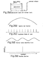
- FIG. la A simplified diagram of a semiconductor laser is shown in Figure la. It consists of two mirrors with a semiconductor gain medium in between. The mirrors are formed by the cleaved facets of respective ends of the semiconductor chip. Two mechanisms combine to determine the wavelengths at which light is emitted. These are the spectral gain function or gain profile, and the longitudinal modes allowed by the dimensions of the laser cavity.
- the spectral gain function defines the range of wavelengths over which the semiconductor material can provide optical gain and is determined by the properties of the semiconductor material. It is a continuous curve as shown in Figure lb.
- the laser longitudinal modes are discrete wavelengths at which lasing can occur.
- the wavelengths of these modes are determined by the length of the laser cavity and by the effective refractive index of the semiconductor material.
- Figure ld shows an emission spectrum which could result from the spectral gain function and longitudinal mode positions shown. Essentially, lasing emission takes place only in those modes whose wavelengths are sufficiently close to the peak of the spectral gain function. This typically results in multi-longitudinal mode operation of the laser, though this is not always the case, for some lasers may operate in a single longitudinal mode even without an external cavity, provided that other conditions (temperature, current etc.) are favourable.
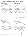
- FIG. 2a A schematic diagram of the semiconductor laser with an external reflector is shown in Figure 2a.
- the effect of the external reflector may be considered as introducing an external cavity whose length L e is determined by the distance between the reflector and the nearest laser facet.
- This external cavity also has cavity modes, but due to the relatively low coupling efficiency between the semiconductor laser and the external cavity, the selectivity curve of the external cavity is much less sharp than that for the laser longitudinal modes ( Figure 2d).
- the positions of the external cavity modes are determined by the cavity length L .
- a change in L e causes the selectivity e e curve of the external cavity to move along the wavelength axis.
- the effect of the additional wavelength selection mechanism introduced by the external cavity is to reduce the loss of laser longitudinal modes near its peak while increasing the loss of modes near its troughs.
- the effect of this on the laser spectrum depends upon the exact positions of the spectral gain function, the laser longitudinal modes and the external cavity modes.
- Figure 3a shows the effect when the peaks of the three curves coincide.
- the central mode has its gain increased by the effect of the external cavity while its two nearest neighbours have their gains reduced.
- the result is that the spectral output from the laser consists of only the central mode. It may be noted that the external cavity also enhances certain other modes, but the reduction in the spectral gain function at these points means that these modes do not lase.
- Figure 3b shows what happens when the tuning of the external cavity is changed, by altering the length L , such e that a peak of the external cavity selectivity curve coincides with a different longitudinal mode of the laser.
- the present invention in its first aspect is based on a discovery by the inventor that single longitudinal mode transmission in a semiconductor laser can be maintained by monitoring the total optical output power from the laser, and need not rely on sensing the wavelength of the emission by means of complex circuitry.
- Methods of controlling lasers by adjusting the length of the laser cavity by sensing the total optical power are known for controlling gas lasers.
- the purpose of such methods is to stabilise and maximise the power output of the laser.
- the cavity of a gas laser is usually relatively long and therefore susceptible to the effects of temperature, which changes the cavity length and hence the wavelength of the lasing mode.
- mount one of the laser mirrors on a piezoelectric support by means of which the mirror may be moved through a small distance. It is to be emphasised that the wavelength of the longitudinal mode varies continuously as the mirror in the gas laser is moved. It is found that the output power from the gas laser is at a maximum when a cavity longitudinal mode is positioned at the peak of the spectral gain function.
- the gas laser can be stabilised by moving the mirror to maximise the laser output.
- the purpose of this method is not to restrict the gas laser to a single longitudinal mode, since it operates in a single mode regardless of the cavity length variations, rather its purpose is to stabilise the wavelength against ambient temperature variations by locking it to the spectral gain function of the lasing medium.
- the purpose of the method of the present invention in its first aspect, is to produce a single longitudinal mode output regardless of the actual wavelength of this mode.
- the present invention in its first aspect, is based on an appreciation of the non-obvious fact that single longitudinal mode operation of a semiconductor laser correlates with a maximisation of its output optical power.
- the total optical power is less than the single mode conditions, as in 3(a) and (b).
- a method of controlling a semiconductor laser for single longitudinal mode operation the laser having an external cavity defined by an external reflector, and the method comprising sensing the radiation output power of the laser and adjusting the optical path length of the external cavity to maximise the radiation output power.
- the optical path length of the external cavity can be adjusted by moving the external reflector.
- the present invention in a first aspect also provides a controlled semiconductor laser adapted to operate in a single longitudinal mode, comprising an external reflector mounted with respect to a facet of the laser to define an external cavity, means for adjusting the optical path length of the cavity, means operative to monitor the radiation output power of the laser and to produce a control signal representative of the magnitude thereof, and signal processing means fed with said control signal and arranged to control said adjusting means to vary the optical path length of said cavity such that the value of the radiation output power of the laser is maximised.
- the reflector may be mounted for translational movement and the adjusting means may include means for accurately moving the reflector.
- the means for accurately moving the external reflector is further controlled to cause the external reflector to undergo a small oscillatory motion about a mean distance from said laser facet, the signal processing means being operative to compare said control signal with respect to the oscillatory position of the reflector and to cause said means for moving the external reflector to adjust the mean position of the reflector to minimise the value of the rate of change in radiation output power with respect to reflector position.
- the movable laser mirror should be controlled to enable precise translational movement through very small distances exists both in the method according to the present invention in its first aspect and in the known systems for stabilising gas lasers.
- Methods suitable for producing such movement have previously been confined to the use of mechanical micro-manipulators or to a technique relying on the thermal expansion of a fine needle supporting the mirror, the heat being generated by passing an electric current through a small heater coil wound on the needle. If active maximisation of the optical power produced by the lasers is desired this will require the position of the mirror to be modulated about a mean position (described further below).
- a variable length cavity for a laser comprising an external reflector, defining the length of the cavity including or having in moving association therewith, magnetically responsible material, the position of the reflector with respect to a mirror of the laser being accurately controlled over a range of distances by an electromagnet producing a magnetic force on said magnetically-responsive material.
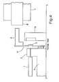
- a laser transmitter module interfaces with a lensed tail of an optical fibre 1 which forms part of a long-haul, high-bit rate optical signalling system.
- the laser included in the module comprises an InGaAsP buried crescent laser diode 2, as described in Electron Lett, 1981, 17 (18), pp 651-653.
- the laser diode 2 has an operating wavelength of approximately 1.51 um and has a threshold current of 34mA at a heatsink temperature of 20°C.
- the optical fibre and the laser diode 2 are both mounted on a copper submount 3, the laser diode being mounted on a pedestal portion of the submount so that both its facets are accessible and so that its front facet is optically coupled to the end of the fibre tail.
- a polished copper foil reflector 4 includes a spherically concave central portion 5.
- the reflector is mounted by bonding with epoxy resin, soldering or laser welding to secure a lower peripheral portion of the foil reflector to a facing surface of the submount 3, below the level of the laser diode.
- the copper foil extends perpendicularly to the path of the laser beam so that the concave reflecting portion 5 is spaced by a short distance behind the rear facet of the laser diode.
- the reflector thus defines an external cavity of the laser diode.
- the concave portion 5 of the reflector has one or more small holes to allow a small portion of the laser radiation to emerge for detection. The alignment and spacing of the reflector with respect to the rear facet of the laser is determined during manufacture of the module.
- a shaped piece of ferromagnetic material 6 is attached to the upper margin of the rear face of the reflector 4.
- a small electromagnet 7 having a pole piece 8 is located to the rear of the piece of ferromagnetic material 6 and spaced therefrom by a small gap.
- a monitor photodiode 9 is located behind the holes in the reflector 4 and so disposed that during laser emission the fraction of the radiation transmitted through the holes is incident on the diode surface.
- Fine adjustment of the length of the external cavity of the laser diode is achieved by passing a current through the coil of the electromagnet 7.
- the resultant magnetic attraction of the piece of ferromagnetic material 6 to the pole piece 8 of the electromagnetic cause the copper foil to flex slightly and thereby alters the distance between the concave reflecting portion of the foil and the near laser facet.
- movement of the reflector through a range of 1 micron is sufficient to tune the external cavity through its complete range, and this may correspond to a coil current of 10mA at 2v.
- restriction of the laser to single mode operation is carried out by active monitoring of the laser output.
- the control circuitry used in association with the transmitter module is shown in Figure 5.
- the electrical coil 10 of the electromagnet, the laser diode 2 and the monitor photodiode 9 are connected to a single integrated circuit board housing the circuit components.
- the circuit includes a feedback loop including a connection from the cathode of the monitor photodiode 9 via, an operational amplifier 10 to one input terminal of a comparator 11.
- a second input terminal to th comparator 11 is connected to a reference signal source 12. This feedback loop is completed by a connection from the output terminal of the comparator 11 to the cathode of the laser diode.
- a further feedback loop also uses the amplified signals from the monitor photodide 9.
- the output terminal from the amplifier 10 is connected to one input terminal of a phase-sensitive detector 13, a second input terminal of which being connected to receive signals from an oscillator 14.
- the output of the phase-sensitive detector is connected to one input terminal of a comparator 15 having another input terminal connected to a reference signal source 16.
- the coil 10 of the electromagnet is connected for current supply from the comparator 15 and from the oscillator 14 via a capacitor 17.
- the first feedback loop operates to stabilise the mean power of the laser output as follows.
- the photocurrent through the monitor photodiode 9 indicative of the optical power output of the laser 2 is amplified and compared at the comparator 11 with a reference value.
- the reference value is chosen at some suitable value and any deviation for this value results in a signal from the output of the comparator 11 to adjust the laser bias current.
- This feedback loop thus maintains the optical power output of the laser at a substantially constant value and is thus able to compensate for the effects of temperature and aging.
- the second feedback loop embodies the present invention and includes a comparison at the phase sensitive detector 13 of the oscillator signal and the amplified mean photocurrent.
- the oscillator 14 produces a small amplitude signal at approximately 500Hz. This signal, applied to the coil 10 of the electromagnet causes a small modulation in the length of the external cavity, and hence a variation in the laser output power. The value of the photocurrent from the monitor photodiode 9 reflects this variation.
- the phase detector 13 produces an output which is proportional to the first derivative of the laser power with respect to reflector position. This output has a polarity depending on the relative position of the external reflector compared with the position at which the power output is at a maximum.
- the output signal from this phase sensitive detector is amplified and fed to the coil 10 to adjust the mean current flowing through the coil.
- the loop thus acts to adjust the coil signal to maintain the laser power output at a maximum or minimum, and the polarity of the feedback signal is chosen so that it is tuned towards a point of maximum rather than minimum power output. Since the power maxima repeat with reflector position, corresponding to different laser longitudinal modes, the circuit can lock to any of those modes that the external cavity can select.
- the loop gains and time constants of the two feedback circuits are carefully chosen so that they do not adversely affect one another.
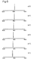
- the control circuit was set up with the transmitter module at a temperature of 20 0 C and an optical power output corresponding to a laser bias current of 50 mA. Single longitudinal mode operation was obtained and the output from the monomode fibre tail was monitored at a 1m monochromator. The temperature of the transmitter module was then changed gradually from 15°C to 40°C. Single longitudinal mode operation was maintained throughout this temperature range. Figure 6 shows the normalised peak heights of spectra results at discrete temperatures through the range. It will be seen that the control circuit has successfully tracked one of the longitudinal modes of the laser, even though the wavelength of the mode has changed by about 2nm with the temperature change of 25°C.
Applications Claiming Priority (2)
| Application Number | Priority Date | Filing Date | Title |
|---|---|---|---|
| GB8231608 | 1982-11-05 | ||
| GB8231608 | 1982-11-05 |
Publications (1)
| Publication Number | Publication Date |
|---|---|
| EP0108562A1 true EP0108562A1 (de) | 1984-05-16 |
Family
ID=10534047
Family Applications (1)
| Application Number | Title | Priority Date | Filing Date |
|---|---|---|---|
| EP83306536A Ceased EP0108562A1 (de) | 1982-11-05 | 1983-10-27 | Verfahren und Vorrichtung zum Steuern von Lasern |
Country Status (3)
| Country | Link |
|---|---|
| US (1) | US4748632A (de) |
| EP (1) | EP0108562A1 (de) |
| JP (1) | JPS5998579A (de) |
Cited By (10)
| Publication number | Priority date | Publication date | Assignee | Title |
|---|---|---|---|---|
| EP0206745A2 (de) * | 1985-06-18 | 1986-12-30 | Sharp Kabushiki Kaisha | Halbleiterlaservorrichtung |
| DE3642445A1 (de) * | 1985-12-10 | 1987-06-11 | Sharp Kk | Resonatoranordnung mit einem halbleiter-laser |
| US4831632A (en) * | 1986-06-27 | 1989-05-16 | British Aerospace Public Limited Company | Method and apparatus for optically aligning a laser cavity |
| EP0348039A2 (de) * | 1988-06-24 | 1989-12-27 | Reiton Corporation | Lasermessvorrichtung |
| EP0365994A2 (de) * | 1988-10-22 | 1990-05-02 | Alcatel SEL Aktiengesellschaft | Geregelter Halbleiterlaser |
| GB2257294A (en) * | 1991-05-10 | 1993-01-06 | Amoco Corp | Controlling laser operation. |
| GB2276973A (en) * | 1993-03-20 | 1994-10-12 | Gec Ferranti Defence Syst | A pulsed laser |
| US5629951A (en) * | 1995-10-13 | 1997-05-13 | Chang-Hasnain; Constance J. | Electrostatically-controlled cantilever apparatus for continuous tuning of the resonance wavelength of a fabry-perot cavity |
| DE19615396A1 (de) * | 1996-04-18 | 1998-01-02 | Laserspec Analytik Gmbh | Verfahren zur Einstellung und Kontrolle der longitudinalen Resonatormode einer Laserstrahlungsquelle |
| WO2011073110A1 (en) * | 2009-12-14 | 2011-06-23 | Vrije Universiteit Brussel | Transverse laser mode switching |
Families Citing this family (38)
| Publication number | Priority date | Publication date | Assignee | Title |
|---|---|---|---|---|
| GB8522821D0 (en) * | 1985-09-16 | 1985-10-23 | British Telecomm | Frequency referencing system |
| JPS6362388A (ja) * | 1986-09-03 | 1988-03-18 | Hitachi Ltd | 半導体レ−ザ装置 |
| US4878724A (en) * | 1987-07-30 | 1989-11-07 | Trw Inc. | Electrooptically tunable phase-locked laser array |
| EP0308603A1 (de) * | 1987-09-25 | 1989-03-29 | Siemens Aktiengesellschaft | Dynamisch einmodiger Lasersender |
| DE3732433A1 (de) * | 1987-09-26 | 1989-04-06 | Standard Elektrik Lorenz Ag | Lasermodul und verfahren zum ankoppeln einer glasfaser |
| US4910738A (en) * | 1987-11-27 | 1990-03-20 | Matsushita Electric Industrial Co., Ltd. | Short optical pulse generators using mode-locked semiconductor lasers oscillating in transverse magnetic modes |
| JP2520153B2 (ja) * | 1988-07-01 | 1996-07-31 | 国際電信電話株式会社 | 半導体レ―ザ光源制御装置 |
| JP2527007B2 (ja) * | 1988-09-29 | 1996-08-21 | 日本電気株式会社 | 光機能素子 |
| US5115439A (en) * | 1989-11-29 | 1992-05-19 | Spectra-Physics Lasers, Inc. | Pole piece to shape axial magnetic field in gas laser |
| US5047639A (en) * | 1989-12-22 | 1991-09-10 | Wong Jacob Y | Concentration detector |
| US5090019A (en) * | 1991-01-10 | 1992-02-18 | The United States Of America As Represented By The Secretary Of The Navy | Laser diode-pumped tunable solid state laser |
| US5247167A (en) * | 1992-08-06 | 1993-09-21 | International Business Machines Corporation | Multiple beam power monitoring system and method with radiation detection and focusing means of overlapping beams |
| US5615052A (en) * | 1993-04-16 | 1997-03-25 | Bruce W. McCaul | Laser diode/lens assembly |
| US5625189A (en) * | 1993-04-16 | 1997-04-29 | Bruce W. McCaul | Gas spectroscopy |
| US5500768A (en) * | 1993-04-16 | 1996-03-19 | Bruce McCaul | Laser diode/lens assembly |
| US5448071A (en) * | 1993-04-16 | 1995-09-05 | Bruce W. McCaul | Gas spectroscopy |
| JP2746227B2 (ja) * | 1995-09-29 | 1998-05-06 | 日本電気株式会社 | イオンレーザ装置 |
| US6198580B1 (en) | 1998-08-17 | 2001-03-06 | Newport Corporation | Gimballed optical mount |
| US6516130B1 (en) | 1998-12-30 | 2003-02-04 | Newport Corporation | Clip that aligns a fiber optic cable with a laser diode within a fiber optic module |
| US6154471A (en) * | 1999-02-22 | 2000-11-28 | Lucent Technologies Inc. | Magnetically tunable and latchable broad-range semiconductor laser |
| FR2790115B1 (fr) | 1999-02-23 | 2001-05-04 | Micro Controle | Procede et dispositif pour deplacer un mobile sur une base montee elastiquement par rapport au sol |
| US6996506B2 (en) * | 1999-02-23 | 2006-02-07 | Newport Corporation | Process and device for displacing a moveable unit on a base |
| US6511035B1 (en) | 1999-08-03 | 2003-01-28 | Newport Corporation | Active vibration isolation systems with nonlinear compensation to account for actuator saturation |
| DE19961056A1 (de) * | 1999-12-20 | 2001-06-21 | Thomson Brandt Gmbh | Laserregelkreis mit automatischer Anpassung an die Monitorsignalpolarität |
| US6580516B1 (en) * | 2000-11-01 | 2003-06-17 | Agilent Technologies, Inc. | Tunable Fabry Perot microelectromechanical resonator adapted for optical filters and lasers with reduced optical power-dependent tuning |
| US6655840B2 (en) | 2001-02-13 | 2003-12-02 | Newport Corporation | Stiff cross roller bearing configuration |
| US6601524B2 (en) | 2001-03-28 | 2003-08-05 | Newport Corporation | Translation table with a spring biased dovetail bearing |
| US6791058B2 (en) | 2001-04-25 | 2004-09-14 | Newport Corporation | Automatic laser weld machine for assembling photonic components |
| US6568666B2 (en) | 2001-06-13 | 2003-05-27 | Newport Corporation | Method for providing high vertical damping to pneumatic isolators during large amplitude disturbances of isolated payload |
| US6717964B2 (en) * | 2001-07-02 | 2004-04-06 | E20 Communications, Inc. | Method and apparatus for wavelength tuning of optically pumped vertical cavity surface emitting lasers |
| US6619611B2 (en) | 2001-07-02 | 2003-09-16 | Newport Corporation | Pneumatic vibration isolator utilizing an elastomeric element for isolation and attenuation of horizontal vibration |
| US6966535B2 (en) * | 2002-05-07 | 2005-11-22 | Newport Corporation | Snubber for pneumatically isolated platforms |
| JP2004221321A (ja) * | 2003-01-15 | 2004-08-05 | Mitsubishi Electric Corp | 波長可変半導体光装置 |
| US7065112B2 (en) * | 2003-05-12 | 2006-06-20 | Princeton Optronics, Inc. | Wavelength locker |
| US20050068245A1 (en) * | 2003-09-25 | 2005-03-31 | Cheng-Chung Chen | Reflective signal booster for omini-antenna |
| US7320455B2 (en) | 2003-10-24 | 2008-01-22 | Newport Corporation | Instrumented platform for vibration-sensitive equipment |
| US8231098B2 (en) | 2004-12-07 | 2012-07-31 | Newport Corporation | Methods and devices for active vibration damping of an optical structure |
| KR100803222B1 (ko) | 2007-01-26 | 2008-02-14 | 삼성전자주식회사 | 스펙클 저감 레이저와 이를 채용한 레이저 디스플레이 장치 |
Citations (3)
| Publication number | Priority date | Publication date | Assignee | Title |
|---|---|---|---|---|
| US3835415A (en) * | 1972-06-28 | 1974-09-10 | Ibm | High radiance semiconductor laser |
| US4237427A (en) * | 1978-06-16 | 1980-12-02 | International Telephone And Telegraph Corporation | Apparatus for stabilizing a laser |
| US4355395A (en) * | 1978-04-10 | 1982-10-19 | British Telecommunications | Injection lasers |
Family Cites Families (9)
| Publication number | Priority date | Publication date | Assignee | Title |
|---|---|---|---|---|
| US3517328A (en) * | 1965-10-24 | 1970-06-23 | Dryden Hugh L | Method and apparatus for stabilizing a gaseous optical maser |
| FR2070473A5 (de) * | 1969-12-05 | 1971-09-10 | Telecommunications Sa | |
| US3793595A (en) * | 1971-12-27 | 1974-02-19 | Perkin Elmer Corp | Single frequency stabilized laser |
| US4046462A (en) * | 1976-04-28 | 1977-09-06 | Nasa | Three-dimensional tracking solar energy concentrator and method for making same |
| JPS5821436B2 (ja) * | 1979-01-16 | 1983-04-30 | 日本電信電話株式会社 | 半導体レ−ザ装置 |
| JPS56150886A (en) * | 1980-04-23 | 1981-11-21 | Nippon Telegr & Teleph Corp <Ntt> | Oscillating frequency stabilized semiconductor laser device |
| US4516242A (en) * | 1981-06-18 | 1985-05-07 | Tokyo Shibaura Denki Kabushiki Kaisha | Output stabilizing device |
| US4504950A (en) * | 1982-03-02 | 1985-03-12 | California Institute Of Technology | Tunable graded rod laser assembly |
| US4461006A (en) * | 1982-03-23 | 1984-07-17 | The United States Of America As Represented By The Secretary Of The Air Force | Synchronously pumped mode-locked semiconductor platelet laser |
-
1983
- 1983-10-27 EP EP83306536A patent/EP0108562A1/de not_active Ceased
- 1983-11-03 US US06/548,480 patent/US4748632A/en not_active Expired - Lifetime
- 1983-11-04 JP JP58208191A patent/JPS5998579A/ja active Granted
Patent Citations (3)
| Publication number | Priority date | Publication date | Assignee | Title |
|---|---|---|---|---|
| US3835415A (en) * | 1972-06-28 | 1974-09-10 | Ibm | High radiance semiconductor laser |
| US4355395A (en) * | 1978-04-10 | 1982-10-19 | British Telecommunications | Injection lasers |
| US4237427A (en) * | 1978-06-16 | 1980-12-02 | International Telephone And Telegraph Corporation | Apparatus for stabilizing a laser |
Non-Patent Citations (4)
| Title |
|---|
| ELECTRONICS LETTERS, vol. 17, no. 24, November 1981, pages 931-933, London, GB. * |
| ELECTRONICS LETTERS, vol. 18, no. 2, 21st January 1982, pages 69-71, London, GB. * |
| IEEE JOURNAL OF QUANTUM ELECTRONICS, vol. 9, no. 2, February 1973, pages 392-394, New York, USA * |
| JOURNAL OF PHYSICS E. SCIENTIFIC INSTRUMENTS, vol. 15, no. 1, January 1982, pages 50-52, Dorking, GB. * |
Cited By (16)
| Publication number | Priority date | Publication date | Assignee | Title |
|---|---|---|---|---|
| EP0206745A3 (en) * | 1985-06-18 | 1988-01-27 | Sharp Kabushiki Kaisha | A semiconductor laser apparatus |
| US4773077A (en) * | 1985-06-18 | 1988-09-20 | Sharp Kabushiki Kaisha | Internal reflection interferometric semiconductor laser apparatus |
| EP0206745A2 (de) * | 1985-06-18 | 1986-12-30 | Sharp Kabushiki Kaisha | Halbleiterlaservorrichtung |
| DE3642445A1 (de) * | 1985-12-10 | 1987-06-11 | Sharp Kk | Resonatoranordnung mit einem halbleiter-laser |
| US4831632A (en) * | 1986-06-27 | 1989-05-16 | British Aerospace Public Limited Company | Method and apparatus for optically aligning a laser cavity |
| EP0348039A3 (en) * | 1988-06-24 | 1990-07-18 | Reiton Corporation | Laser measuring devices |
| EP0348039A2 (de) * | 1988-06-24 | 1989-12-27 | Reiton Corporation | Lasermessvorrichtung |
| EP0365994A3 (de) * | 1988-10-22 | 1990-11-22 | Alcatel SEL Aktiengesellschaft | Geregelter Halbleiterlaser |
| EP0365994A2 (de) * | 1988-10-22 | 1990-05-02 | Alcatel SEL Aktiengesellschaft | Geregelter Halbleiterlaser |
| GB2257294A (en) * | 1991-05-10 | 1993-01-06 | Amoco Corp | Controlling laser operation. |
| GB2257294B (en) * | 1991-05-10 | 1994-11-02 | Amoco Corp | Automated single longitudinal mode locking system |
| GB2276973A (en) * | 1993-03-20 | 1994-10-12 | Gec Ferranti Defence Syst | A pulsed laser |
| US5646952A (en) * | 1993-03-20 | 1997-07-08 | Gec-Marconi Avionics (Holdings) Limited | Laser |
| US5629951A (en) * | 1995-10-13 | 1997-05-13 | Chang-Hasnain; Constance J. | Electrostatically-controlled cantilever apparatus for continuous tuning of the resonance wavelength of a fabry-perot cavity |
| DE19615396A1 (de) * | 1996-04-18 | 1998-01-02 | Laserspec Analytik Gmbh | Verfahren zur Einstellung und Kontrolle der longitudinalen Resonatormode einer Laserstrahlungsquelle |
| WO2011073110A1 (en) * | 2009-12-14 | 2011-06-23 | Vrije Universiteit Brussel | Transverse laser mode switching |
Also Published As
| Publication number | Publication date |
|---|---|
| US4748632A (en) | 1988-05-31 |
| JPS5998579A (ja) | 1984-06-06 |
| JPH0559595B2 (de) | 1993-08-31 |
Similar Documents
| Publication | Publication Date | Title |
|---|---|---|
| US4748632A (en) | Method and apparatus for controlling lasers | |
| US6181717B1 (en) | Tunable semiconductor laser system | |
| US5107512A (en) | Frequency stabilization of a laser beam by using a birefrigent body | |
| US5181214A (en) | Temperature stable solid-state laser package | |
| US20060193354A1 (en) | External Cavity Tunable Laser and Control | |
| US20030099273A1 (en) | Method and apparatus for coupling a surface-emitting laser to an external device | |
| EP3419122B1 (de) | Optische vorrichtung | |
| US6594022B1 (en) | Wavelength reference device | |
| WO1983002856A1 (en) | Semiconductor lasers | |
| CN109863655B (zh) | 基于布拉格光栅的超低噪声、高稳定单模工作、高功率半导体激光器 | |
| US20080002746A1 (en) | Optical transmitters | |
| US20060109873A1 (en) | External cavity laser having improved single mode operation | |
| EP0404857B1 (de) | Laser-frequenzsteuerung | |
| JPH11238946A (ja) | レーザ・モジュールおよびその波長および光パワーを同時に安定化させる方法 | |
| US6526078B2 (en) | Light source | |
| US6717707B2 (en) | Method and system for controlling resonance within a resonator-enhanced optical system | |
| EP0446345B1 (de) | Strahlungsquelle für heliummagnetometer | |
| US6996144B2 (en) | Wavelength stabilization of tunable lasers by current modulation | |
| US5124994A (en) | Light generating device | |
| EP1427077B1 (de) | Laser mit externem Resonator und verbessertem Einzelmodenbetrieb | |
| WO1995029521A1 (en) | Frequency stabilisation of a laser diode | |
| EP0060033A1 (de) | Laser-Lichtquelle | |
| JP2009081321A (ja) | 波長安定化レーザ装置および方法,ならびに波長安定化レーザ装置を備えたラマン増幅器 | |
| US6441940B1 (en) | Wavelength stabilization of light emitting components | |
| WO2001035502A1 (en) | Wavelength stabilization of tunable lasers by current modulation |
Legal Events
| Date | Code | Title | Description |
|---|---|---|---|
| PUAI | Public reference made under article 153(3) epc to a published international application that has entered the european phase |
Free format text: ORIGINAL CODE: 0009012 |
|
| AK | Designated contracting states |
Designated state(s): AT BE CH DE FR GB IT LI LU NL SE |
|
| 17P | Request for examination filed |
Effective date: 19840521 |
|
| STAA | Information on the status of an ep patent application or granted ep patent |
Free format text: STATUS: THE APPLICATION HAS BEEN REFUSED |
|
| 18R | Application refused |
Effective date: 19860623 |
|
| RIN1 | Information on inventor provided before grant (corrected) |
Inventor name: PRESTON, KEITH ROBERT |