EP0239741B1 - Doppelrohr, bestehend aus zwei einstückig über einen Steg miteinander verbundenen Schutzrohren - Google Patents
Doppelrohr, bestehend aus zwei einstückig über einen Steg miteinander verbundenen Schutzrohren Download PDFInfo
- Publication number
- EP0239741B1 EP0239741B1 EP87101327A EP87101327A EP0239741B1 EP 0239741 B1 EP0239741 B1 EP 0239741B1 EP 87101327 A EP87101327 A EP 87101327A EP 87101327 A EP87101327 A EP 87101327A EP 0239741 B1 EP0239741 B1 EP 0239741B1
- Authority
- EP
- European Patent Office
- Prior art keywords
- web
- tubes
- circular cylindrical
- cylindrical portions
- double tube
- Prior art date
- Legal status (The legal status is an assumption and is not a legal conclusion. Google has not performed a legal analysis and makes no representation as to the accuracy of the status listed.)
- Expired
Links
- 229920003023 plastic Polymers 0.000 claims description 2
- 239000004033 plastic Substances 0.000 claims description 2
- 230000001681 protective effect Effects 0.000 abstract description 37
- 229920002457 flexible plastic Polymers 0.000 abstract description 3
- 238000009428 plumbing Methods 0.000 abstract 1
- 238000004519 manufacturing process Methods 0.000 description 3
- 239000011324 bead Substances 0.000 description 2
- 238000010276 construction Methods 0.000 description 2
- 238000010616 electrical installation Methods 0.000 description 2
- 230000002349 favourable effect Effects 0.000 description 2
- 238000009434 installation Methods 0.000 description 2
- 238000000034 method Methods 0.000 description 2
- XLYOFNOQVPJJNP-UHFFFAOYSA-N water Substances O XLYOFNOQVPJJNP-UHFFFAOYSA-N 0.000 description 2
- 239000004698 Polyethylene Substances 0.000 description 1
- 238000009825 accumulation Methods 0.000 description 1
- 239000003086 colorant Substances 0.000 description 1
- 238000005520 cutting process Methods 0.000 description 1
- 238000009826 distribution Methods 0.000 description 1
- 238000010438 heat treatment Methods 0.000 description 1
- 239000008236 heating water Substances 0.000 description 1
- 230000001771 impaired effect Effects 0.000 description 1
- 239000000463 material Substances 0.000 description 1
- 238000005457 optimization Methods 0.000 description 1
- -1 polyethylene Polymers 0.000 description 1
- 229920000573 polyethylene Polymers 0.000 description 1
- 238000000926 separation method Methods 0.000 description 1
- 230000007704 transition Effects 0.000 description 1
Images

Classifications
-
- F—MECHANICAL ENGINEERING; LIGHTING; HEATING; WEAPONS; BLASTING
- F16—ENGINEERING ELEMENTS AND UNITS; GENERAL MEASURES FOR PRODUCING AND MAINTAINING EFFECTIVE FUNCTIONING OF MACHINES OR INSTALLATIONS; THERMAL INSULATION IN GENERAL
- F16L—PIPES; JOINTS OR FITTINGS FOR PIPES; SUPPORTS FOR PIPES, CABLES OR PROTECTIVE TUBING; MEANS FOR THERMAL INSULATION IN GENERAL
- F16L3/00—Supports for pipes, cables or protective tubing, e.g. hangers, holders, clamps, cleats, clips, brackets
- F16L3/08—Supports for pipes, cables or protective tubing, e.g. hangers, holders, clamps, cleats, clips, brackets substantially surrounding the pipe, cable or protective tubing
- F16L3/12—Supports for pipes, cables or protective tubing, e.g. hangers, holders, clamps, cleats, clips, brackets substantially surrounding the pipe, cable or protective tubing comprising a member substantially surrounding the pipe, cable or protective tubing
-
- F—MECHANICAL ENGINEERING; LIGHTING; HEATING; WEAPONS; BLASTING
- F16—ENGINEERING ELEMENTS AND UNITS; GENERAL MEASURES FOR PRODUCING AND MAINTAINING EFFECTIVE FUNCTIONING OF MACHINES OR INSTALLATIONS; THERMAL INSULATION IN GENERAL
- F16L—PIPES; JOINTS OR FITTINGS FOR PIPES; SUPPORTS FOR PIPES, CABLES OR PROTECTIVE TUBING; MEANS FOR THERMAL INSULATION IN GENERAL
- F16L3/00—Supports for pipes, cables or protective tubing, e.g. hangers, holders, clamps, cleats, clips, brackets
- F16L3/22—Supports for pipes, cables or protective tubing, e.g. hangers, holders, clamps, cleats, clips, brackets specially adapted for supporting a number of parallel pipes at intervals
- F16L3/237—Supports for pipes, cables or protective tubing, e.g. hangers, holders, clamps, cleats, clips, brackets specially adapted for supporting a number of parallel pipes at intervals for two pipes
Definitions
- the invention relates to a double tube according to the first part of claim 1.
- Such a double pipe known from DE-C-12 18 574 is used for electrical installation. It is attached by nailing, driving the nail through the web to create a hole, in the area between two opposing troughs. There is a very high risk that the web will tear. This is in itself not important when using the known double tube. However, if such a double pipe is also to be used for sanitary purposes, it must be ensured that it cannot be damaged during installation.
- the invention has for its object to design a double tube of the generic type so that it can be installed in a simple manner, without the risk of damage or deformation and without its flexibility in the main plane formed by the axes of the two protective tubes is impaired .
- the special design of the mounting hole ensures that tearing of the web and thus damage to at least one protective tube is excluded when laying and securing the double tube by means of screws or nails.
- the arrangement and design of the fastening hole according to the invention make it possible to give the web connecting the two protective tubes an extremely small width, so that the flexibility of the double tube in the plane spanned by the two axes of the protective tubes is extremely favorable. Since the fastening means, in particular a screw, does not lie directly against the web, and since the secant-shaped boundary walls of the fastening hole in this area give the protective tubes a high crest strength, deformations of the tube during installation and fastening are excluded. For this reason, the double pipe according to the invention can also be used in a particularly advantageous manner for sanitary purposes, with an additional flexible pipe being provided in the respective protective pipe.
- Claim 2 shows a particularly favorable and space-saving design of the double pipe in the region of the fastening hole.
- Claim 3 specifies an optimal width for the web, i.e. an optimization of the flexibility of the double pipe.
- the development according to claim 4 leads to a particularly preferred application.
- the double tube design makes it very rigid in the longitudinal direction. This makes it easier to insert the inner tube compared to simple protective tubes. The relatively high rigidity also reduces the risk of lateral deflection when laying on the construction site if a worker trips over the tube.
- two separately attached inner tubes are arranged, one of which serves as a supply line 8 and one as a return line 9, namely the supply line 8 is used to supply warm or hot water to a radiator and the return line 9 for discharge of the water cooled in the radiator.
- the flow line 8 and the return line 9 consist of a thermally sufficiently stable and, on the other hand, sufficiently flexible plastic so that curvatures are easily possible.
- the described double tube is produced in one piece by the so-called vacuum process between rotating molds which form a moving form and are connected to form endless chains.
- This widespread technique is known for example from DE-C-20 61 027 (corresponding to US-A-3 776 679).
- a bead 13 in the manner of a weld seam is formed in the transition area between the web 5 and the protective tube 1 and the protective tube 2 on the inside thereof. a slight accumulation of material.
- the boundary wall 12 is offset radially outwards in relation to section 4 by a wall thickness b in the manner described.
- the boundary wall 12 can be slightly inclined outwards towards the interior of the respective protective tube 1 or 2, starting from the web 5, in order to facilitate demolding of the double tube after manufacture.
- fastening pieces 14 are used, as shown in FIGS. 5 and 6. Fastening pieces of this type fill the respective gusset area between the protective tubes 1 and 2 on both sides of the web 5. As can be seen in FIG. 5, the two cylindrical-section-shaped side faces 15 of each fastening piece 14 lie against the two mutually opposite sections 3.
- a bore 16 in the respective fastening piece 14 is aligned with the fastening hole 11 in the double tube, so that a fastening screw 17 penetrates from above the bore 16 of an upper fastening piece 14, the fastening hole 11 and the bore 16 in a lower fastening piece 14 before it is threaded 18 penetrate into a dowel 19 in a corresponding hole 20 in the floor 10 or a wall.
- a countersunk recess 23 coaxial with the bore 16 is formed in the outer surface 22 of each fastening piece 14. As can be seen in particular in FIGS.
- each fastening piece runs tangentially to the two Protective tubes 1, 2 and consequently approximately parallel to the plane spanned by the axes 6, 7 of the protective tubes 1, 2. For this reason, the pressure applied when the fastening screw 17 is tightened by means of the fastening piece 14 assigned to the head 21 is essentially transmitted to the floor 10 or the wall via the fastening piece 14 assigned to the floor 10 or the wall.
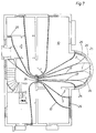
- a plurality of double pipes are laid, starting from a central distribution device 24 on the floor 10 of a house, to form individual radiators 25, 26.
- the double tube is moved up to the radiator 25 without the two protective tubes 1, 2 being pulled apart after severing the web 5.
- Such a separation of the web 5 and a corresponding fanning out of the protective tubes 1, 2 takes place, on the other hand, in the case of the radiators 26, in which the supply line 8 is connected on one side and the return line 9 on the other side of the radiator 26.
- the double tube Since on the one hand the web 5 has a very small width s according to the above illustration, and since the double tube also consists of a relatively flexible plastic, such as polyethylene, the double tube can be laid with very narrow radii of curvature without the web 5 being severed will.
- the radius of curvature r in the plane spanned by the two axes 6, 7 is r - 150 mm.
- a radius of curvature of about 50 mm applies here. In this case, the bend was perpendicular to the plane spanned by the axes 6, 7, which leads to the reduction in the radius of curvature mentioned.
- the protective tubes 1, 2 can in principle not be designed in different colors, which is common for such tubes for sanitary applications. For this reason, a tube can be provided with one or more color strips 27 which, for. B. are red on blue tubes or blue on red tubes. These color strips 27 serve to facilitate assembly.
Landscapes
- Engineering & Computer Science (AREA)
- General Engineering & Computer Science (AREA)
- Mechanical Engineering (AREA)
- Rigid Pipes And Flexible Pipes (AREA)
- Supports For Pipes And Cables (AREA)
- Laying Of Electric Cables Or Lines Outside (AREA)
- Tents Or Canopies (AREA)
- Joints That Cut Off Fluids, And Hose Joints (AREA)
Priority Applications (1)
| Application Number | Priority Date | Filing Date | Title |
|---|---|---|---|
| AT87101327T ATE36393T1 (de) | 1986-03-29 | 1987-01-31 | Doppelrohr, bestehend aus zwei einstueckig ueber einen steg miteinander verbundenen schutzrohren. |
Applications Claiming Priority (2)
| Application Number | Priority Date | Filing Date | Title |
|---|---|---|---|
| DE19863610667 DE3610667A1 (de) | 1986-03-29 | 1986-03-29 | Doppelrohr bestehend aus zwei einstueckig ueber einen steg miteinander verbundenen schutzrohren |
| DE3610667 | 1986-03-29 |
Publications (2)
| Publication Number | Publication Date |
|---|---|
| EP0239741A1 EP0239741A1 (de) | 1987-10-07 |
| EP0239741B1 true EP0239741B1 (de) | 1988-08-10 |
Family
ID=6297542
Family Applications (1)
| Application Number | Title | Priority Date | Filing Date |
|---|---|---|---|
| EP87101327A Expired EP0239741B1 (de) | 1986-03-29 | 1987-01-31 | Doppelrohr, bestehend aus zwei einstückig über einen Steg miteinander verbundenen Schutzrohren |
Country Status (8)
| Country | Link |
|---|---|
| US (1) | US4773451A (enExample) |
| EP (1) | EP0239741B1 (enExample) |
| JP (1) | JPS62233587A (enExample) |
| CN (1) | CN1007288B (enExample) |
| AT (1) | ATE36393T1 (enExample) |
| CA (1) | CA1281661C (enExample) |
| DE (2) | DE3610667A1 (enExample) |
| SU (1) | SU1692307A3 (enExample) |
Families Citing this family (9)
| Publication number | Priority date | Publication date | Assignee | Title |
|---|---|---|---|---|
| JPH0733021Y2 (ja) * | 1988-02-16 | 1995-07-31 | 臼井国際産業株式会社 | クランプ体による配管の一括集中固定構造 |
| DE19932800A1 (de) * | 1999-07-14 | 2001-01-18 | Volkswagen Ag | Trägeranordnung mit einer Strömungsmittelleitung für einen Fahrzeugaufbau |
| GB9921557D0 (en) * | 1999-09-14 | 1999-11-17 | Petroline Wellsystems Ltd | Downhole apparatus |
| FR2836602B1 (fr) * | 2002-02-28 | 2004-12-17 | Usinage Tubes Pour Electr | Conduit destine notamment au cheminement de cables |
| FR2836603B1 (fr) * | 2002-02-28 | 2004-12-17 | Usinage Tubes Pour Electr | Conduit destine notamment au cheminement de cables |
| US8246287B1 (en) * | 2008-01-16 | 2012-08-21 | Westendorf Manufacturing, Co. | Guard structure for fluid conduits of hydraulic cylinders and hydraulic lines |
| CN107489825A (zh) * | 2017-07-26 | 2017-12-19 | 江苏泰力机械科技有限公司 | 单双管可变管夹 |
| CN110894899B (zh) * | 2018-09-13 | 2021-11-19 | 陕西重型汽车有限公司 | 双管固定卡箍 |
| CN112518620B (zh) * | 2020-11-30 | 2022-04-19 | 盐城大孙庄新城建设有限公司 | 一种水利管道维修用支撑座 |
Family Cites Families (14)
| Publication number | Priority date | Publication date | Assignee | Title |
|---|---|---|---|---|
| DE584985C (de) * | 1933-09-27 | Georges Jean Curtet | Leiste zur Verlegung elektrischer Leitungen | |
| US100605A (en) * | 1870-03-08 | Improvement in brad-setter | ||
| US1072173A (en) * | 1908-09-29 | 1913-09-02 | Canton Culvert Company | Culvert. |
| US2624366A (en) * | 1952-07-22 | 1953-01-06 | William J Pugh | Plural hose |
| DE1218574B (de) * | 1961-10-19 | 1966-06-08 | Wilhelm Hegler | Kunststoffrohr fuer Elektroinstallation |
| DE2038991C3 (de) * | 1970-08-05 | 1980-10-30 | Gerhard Dipl.-Ing. 8450 Amberg Pruefling | Rohrleitungsanordnung für eine Warmwasserzentralheizungsanlage |
| US3682422A (en) * | 1970-10-05 | 1972-08-08 | Theodore D Evans | Tube clamping member |
| DE2061027C3 (de) * | 1970-12-11 | 1982-03-04 | Wilhelm 8730 Bad Kissingen Hegler | Vorrichtung zum Anbringen einer Querprofilierung an einem Rohr aus thermoplastischem Kunststoff |
| ES166308Y (es) * | 1971-02-20 | 1972-08-01 | Material De Aireacion, S. A. | Tubo plastico multiple. |
| UST100605I4 (en) | 1979-01-10 | 1981-05-05 | Cable clamp with compression limit stop | |
| JPS5621690U (enExample) * | 1979-07-27 | 1981-02-26 | ||
| JPS5849013Y2 (ja) * | 1980-04-17 | 1983-11-09 | 因幡電工株式会社 | 空調配管用ダクトの構造 |
| CA1187258A (en) * | 1982-12-02 | 1985-05-21 | Lupke, Manfred A. A. | Method and apparatus for forming a double walled thermoplastic tube with integral bells |
| US4658854A (en) * | 1985-06-03 | 1987-04-21 | Caterpillar Inc. | Conduit guarding and clamping device |
-
1986
- 1986-03-29 DE DE19863610667 patent/DE3610667A1/de not_active Withdrawn
-
1987
- 1987-01-31 AT AT87101327T patent/ATE36393T1/de not_active IP Right Cessation
- 1987-01-31 DE DE8787101327T patent/DE3760002D1/de not_active Expired
- 1987-01-31 EP EP87101327A patent/EP0239741B1/de not_active Expired
- 1987-03-17 JP JP62060240A patent/JPS62233587A/ja active Granted
- 1987-03-18 US US07/028,176 patent/US4773451A/en not_active Expired - Fee Related
- 1987-03-19 SU SU874202172A patent/SU1692307A3/ru active
- 1987-03-24 CN CN87102248A patent/CN1007288B/zh not_active Expired
- 1987-03-27 CA CA000533234A patent/CA1281661C/en not_active Expired - Lifetime
Also Published As
| Publication number | Publication date |
|---|---|
| US4773451A (en) | 1988-09-27 |
| CA1281661C (en) | 1991-03-19 |
| ATE36393T1 (de) | 1988-08-15 |
| SU1692307A3 (ru) | 1991-11-15 |
| JPS62233587A (ja) | 1987-10-13 |
| EP0239741A1 (de) | 1987-10-07 |
| JPH049954B2 (enExample) | 1992-02-21 |
| DE3760002D1 (en) | 1988-09-15 |
| CN1007288B (zh) | 1990-03-21 |
| CN87102248A (zh) | 1987-10-07 |
| DE3610667A1 (de) | 1987-10-01 |
Similar Documents
| Publication | Publication Date | Title |
|---|---|---|
| DE2728971C3 (de) | Einsatz für ein Wärmetauscherrohr | |
| DE3050690C2 (de) | Wärmetauscher mit einer Wärmetauschermatte aus elastomerem Material | |
| DE69920059T2 (de) | Kunstharzrohrkupplung mit einem Verstärkungsring | |
| DE69912260T2 (de) | Verbinder für rohrförmige elemente | |
| DE3432073A1 (de) | Waermetauscher, insbesondere fuer kraftfahrzeuge, und vorrichtung und verfahren zum verbinden von dessen rohren und lamellen | |
| EP0111271B1 (de) | Leitungsrohr aus Kunststoff, insbesondere für Abwässer | |
| EP0239741B1 (de) | Doppelrohr, bestehend aus zwei einstückig über einen Steg miteinander verbundenen Schutzrohren | |
| DE4435177C2 (de) | Haltersystem für Rohre od. dgl. | |
| EP0773324B2 (de) | Vorrichtung zum Verbinden und zur Aufnahme von Querkräften von zwei durch eine Fuge getrennten Bauteilen | |
| EP0858568B1 (de) | Verfahren zur verbindung eines rohres mit einem pressfitting sowie kombination aus pressfitting, rohr und pressgerät | |
| DE3838935A1 (de) | Kupplungsstueck | |
| DE3109866C2 (de) | Verlegeplatte zum flächigen Verlegen von Rohrleitungen, insbesondere bei einer Fußbodenheizung | |
| EP0447936B1 (de) | Vorrichtung zur Befestigung von Installationselementen | |
| EP3786532B1 (de) | Flächenwärmetauscher, system und verfahren | |
| DE4040495C2 (enExample) | ||
| DE3628326C2 (de) | Stütz- und Halteelement für einen gebogenen Teil einer Rohrleitung | |
| DE69503103T2 (de) | Verfahren zur Befestigung einer Luftzuführung an einem Kühlradiator | |
| EP0583596B1 (de) | Sickerleitungsrohr | |
| WO2007088072A1 (de) | Verbindung zwischen der stirnseite eines kunststoffrohres und einem kunstoffkörper | |
| DE3301229C2 (enExample) | ||
| DE2306999A1 (de) | Waermeuebertrager | |
| EP2653792A1 (de) | Wärmeleitprofil | |
| DE3518813A1 (de) | Flansch zur befestigung von rohren | |
| DE3832399A1 (de) | Rohrhalter und verfahren zur rohrmontage mittels eines rohrhalters | |
| CH660067A5 (de) | Muffenverbindung und verfahren zur montage derselben. |
Legal Events
| Date | Code | Title | Description |
|---|---|---|---|
| PUAI | Public reference made under article 153(3) epc to a published international application that has entered the european phase |
Free format text: ORIGINAL CODE: 0009012 |
|
| AK | Designated contracting states |
Kind code of ref document: A1 Designated state(s): AT CH DE FR GB LI NL SE |
|
| 17P | Request for examination filed |
Effective date: 19870828 |
|
| 17Q | First examination report despatched |
Effective date: 19880209 |
|
| GRAA | (expected) grant |
Free format text: ORIGINAL CODE: 0009210 |
|
| AK | Designated contracting states |
Kind code of ref document: B1 Designated state(s): AT CH DE FR GB LI NL SE |
|
| REF | Corresponds to: |
Ref document number: 36393 Country of ref document: AT Date of ref document: 19880815 Kind code of ref document: T |
|
| GBT | Gb: translation of ep patent filed (gb section 77(6)(a)/1977) | ||
| REF | Corresponds to: |
Ref document number: 3760002 Country of ref document: DE Date of ref document: 19880915 |
|
| ET | Fr: translation filed | ||
| PLBE | No opposition filed within time limit |
Free format text: ORIGINAL CODE: 0009261 |
|
| STAA | Information on the status of an ep patent application or granted ep patent |
Free format text: STATUS: NO OPPOSITION FILED WITHIN TIME LIMIT |
|
| 26N | No opposition filed | ||
| PGFP | Annual fee paid to national office [announced via postgrant information from national office to epo] |
Ref country code: CH Payment date: 19921224 Year of fee payment: 7 |
|
| PGFP | Annual fee paid to national office [announced via postgrant information from national office to epo] |
Ref country code: AT Payment date: 19930105 Year of fee payment: 7 |
|
| ITF | It: translation for a ep patent filed | ||
| PG25 | Lapsed in a contracting state [announced via postgrant information from national office to epo] |
Ref country code: LI Effective date: 19940131 Ref country code: CH Effective date: 19940131 Ref country code: AT Effective date: 19940131 |
|
| REG | Reference to a national code |
Ref country code: CH Ref legal event code: PL |
|
| EAL | Se: european patent in force in sweden |
Ref document number: 87101327.2 |
|
| PGFP | Annual fee paid to national office [announced via postgrant information from national office to epo] |
Ref country code: GB Payment date: 19970113 Year of fee payment: 11 |
|
| PGFP | Annual fee paid to national office [announced via postgrant information from national office to epo] |
Ref country code: SE Payment date: 19970123 Year of fee payment: 11 |
|
| PG25 | Lapsed in a contracting state [announced via postgrant information from national office to epo] |
Ref country code: GB Free format text: LAPSE BECAUSE OF NON-PAYMENT OF DUE FEES Effective date: 19980131 |
|
| PG25 | Lapsed in a contracting state [announced via postgrant information from national office to epo] |
Ref country code: SE Free format text: LAPSE BECAUSE OF NON-PAYMENT OF DUE FEES Effective date: 19980201 |
|
| GBPC | Gb: european patent ceased through non-payment of renewal fee |
Effective date: 19980131 |
|
| EUG | Se: european patent has lapsed |
Ref document number: 87101327.2 |
|
| PGFP | Annual fee paid to national office [announced via postgrant information from national office to epo] |
Ref country code: DE Payment date: 19991209 Year of fee payment: 14 |
|
| PGFP | Annual fee paid to national office [announced via postgrant information from national office to epo] |
Ref country code: FR Payment date: 20000118 Year of fee payment: 14 |
|
| PGFP | Annual fee paid to national office [announced via postgrant information from national office to epo] |
Ref country code: NL Payment date: 20000125 Year of fee payment: 14 |
|
| PG25 | Lapsed in a contracting state [announced via postgrant information from national office to epo] |
Ref country code: NL Free format text: LAPSE BECAUSE OF NON-PAYMENT OF DUE FEES Effective date: 20010801 |
|
| PG25 | Lapsed in a contracting state [announced via postgrant information from national office to epo] |
Ref country code: FR Free format text: LAPSE BECAUSE OF NON-PAYMENT OF DUE FEES Effective date: 20010928 |
|
| NLV4 | Nl: lapsed or anulled due to non-payment of the annual fee |
Effective date: 20010801 |
|
| PG25 | Lapsed in a contracting state [announced via postgrant information from national office to epo] |
Ref country code: DE Free format text: LAPSE BECAUSE OF NON-PAYMENT OF DUE FEES Effective date: 20011101 |
|
| REG | Reference to a national code |
Ref country code: FR Ref legal event code: ST |