EP0238239A2 - Verfahren und Vorrichtung zum Formen eines thermoplastischen Gegenstandes mit einem Schweisseinsatz - Google Patents
Verfahren und Vorrichtung zum Formen eines thermoplastischen Gegenstandes mit einem Schweisseinsatz Download PDFInfo
- Publication number
- EP0238239A2 EP0238239A2 EP87301989A EP87301989A EP0238239A2 EP 0238239 A2 EP0238239 A2 EP 0238239A2 EP 87301989 A EP87301989 A EP 87301989A EP 87301989 A EP87301989 A EP 87301989A EP 0238239 A2 EP0238239 A2 EP 0238239A2
- Authority
- EP
- European Patent Office
- Prior art keywords
- thermoplastics
- moulding
- pad
- fusion pad
- envelope
- Prior art date
- Legal status (The legal status is an assumption and is not a legal conclusion. Google has not performed a legal analysis and makes no representation as to the accuracy of the status listed.)
- Withdrawn
Links
Images

Classifications
-
- B—PERFORMING OPERATIONS; TRANSPORTING
- B29—WORKING OF PLASTICS; WORKING OF SUBSTANCES IN A PLASTIC STATE IN GENERAL
- B29D—PRODUCING PARTICULAR ARTICLES FROM PLASTICS OR FROM SUBSTANCES IN A PLASTIC STATE
- B29D23/00—Producing tubular articles
- B29D23/001—Pipes; Pipe joints
- B29D23/003—Pipe joints, e.g. straight joints
- B29D23/005—Pipe joints, e.g. straight joints provided with electrical wiring
-
- B—PERFORMING OPERATIONS; TRANSPORTING
- B29—WORKING OF PLASTICS; WORKING OF SUBSTANCES IN A PLASTIC STATE IN GENERAL
- B29C—SHAPING OR JOINING OF PLASTICS; SHAPING OF MATERIAL IN A PLASTIC STATE, NOT OTHERWISE PROVIDED FOR; AFTER-TREATMENT OF THE SHAPED PRODUCTS, e.g. REPAIRING
- B29C45/00—Injection moulding, i.e. forcing the required volume of moulding material through a nozzle into a closed mould; Apparatus therefor
- B29C45/14—Injection moulding, i.e. forcing the required volume of moulding material through a nozzle into a closed mould; Apparatus therefor incorporating preformed parts or layers, e.g. injection moulding around inserts or for coating articles
- B29C45/14311—Injection moulding, i.e. forcing the required volume of moulding material through a nozzle into a closed mould; Apparatus therefor incorporating preformed parts or layers, e.g. injection moulding around inserts or for coating articles using means for bonding the coating to the articles
-
- B—PERFORMING OPERATIONS; TRANSPORTING
- B29—WORKING OF PLASTICS; WORKING OF SUBSTANCES IN A PLASTIC STATE IN GENERAL
- B29C—SHAPING OR JOINING OF PLASTICS; SHAPING OF MATERIAL IN A PLASTIC STATE, NOT OTHERWISE PROVIDED FOR; AFTER-TREATMENT OF THE SHAPED PRODUCTS, e.g. REPAIRING
- B29C70/00—Shaping composites, i.e. plastics material comprising reinforcements, fillers or preformed parts, e.g. inserts
- B29C70/68—Shaping composites, i.e. plastics material comprising reinforcements, fillers or preformed parts, e.g. inserts by incorporating or moulding on preformed parts, e.g. inserts or layers, e.g. foam blocks
-
- F—MECHANICAL ENGINEERING; LIGHTING; HEATING; WEAPONS; BLASTING
- F16—ENGINEERING ELEMENTS AND UNITS; GENERAL MEASURES FOR PRODUCING AND MAINTAINING EFFECTIVE FUNCTIONING OF MACHINES OR INSTALLATIONS; THERMAL INSULATION IN GENERAL
- F16L—PIPES; JOINTS OR FITTINGS FOR PIPES; SUPPORTS FOR PIPES, CABLES OR PROTECTIVE TUBING; MEANS FOR THERMAL INSULATION IN GENERAL
- F16L47/00—Connecting arrangements or other fittings specially adapted to be made of plastics or to be used with pipes made of plastics
- F16L47/02—Welded joints; Adhesive joints
- F16L47/03—Welded joints with an electrical resistance incorporated in the joint
-
- F—MECHANICAL ENGINEERING; LIGHTING; HEATING; WEAPONS; BLASTING
- F16—ENGINEERING ELEMENTS AND UNITS; GENERAL MEASURES FOR PRODUCING AND MAINTAINING EFFECTIVE FUNCTIONING OF MACHINES OR INSTALLATIONS; THERMAL INSULATION IN GENERAL
- F16L—PIPES; JOINTS OR FITTINGS FOR PIPES; SUPPORTS FOR PIPES, CABLES OR PROTECTIVE TUBING; MEANS FOR THERMAL INSULATION IN GENERAL
- F16L47/00—Connecting arrangements or other fittings specially adapted to be made of plastics or to be used with pipes made of plastics
- F16L47/26—Connecting arrangements or other fittings specially adapted to be made of plastics or to be used with pipes made of plastics for branching pipes; for joining pipes to walls; Adaptors therefor
- F16L47/32—Branch units, e.g. made in one piece, welded, riveted
-
- B—PERFORMING OPERATIONS; TRANSPORTING
- B29—WORKING OF PLASTICS; WORKING OF SUBSTANCES IN A PLASTIC STATE IN GENERAL
- B29C—SHAPING OR JOINING OF PLASTICS; SHAPING OF MATERIAL IN A PLASTIC STATE, NOT OTHERWISE PROVIDED FOR; AFTER-TREATMENT OF THE SHAPED PRODUCTS, e.g. REPAIRING
- B29C45/00—Injection moulding, i.e. forcing the required volume of moulding material through a nozzle into a closed mould; Apparatus therefor
-
- B—PERFORMING OPERATIONS; TRANSPORTING
- B29—WORKING OF PLASTICS; WORKING OF SUBSTANCES IN A PLASTIC STATE IN GENERAL
- B29C—SHAPING OR JOINING OF PLASTICS; SHAPING OF MATERIAL IN A PLASTIC STATE, NOT OTHERWISE PROVIDED FOR; AFTER-TREATMENT OF THE SHAPED PRODUCTS, e.g. REPAIRING
- B29C65/00—Joining or sealing of preformed parts, e.g. welding of plastics materials; Apparatus therefor
- B29C65/02—Joining or sealing of preformed parts, e.g. welding of plastics materials; Apparatus therefor by heating, with or without pressure
- B29C65/34—Joining or sealing of preformed parts, e.g. welding of plastics materials; Apparatus therefor by heating, with or without pressure using heated elements which remain in the joint, e.g. "verlorenes Schweisselement"
- B29C65/3404—Joining or sealing of preformed parts, e.g. welding of plastics materials; Apparatus therefor by heating, with or without pressure using heated elements which remain in the joint, e.g. "verlorenes Schweisselement" characterised by the type of heated elements which remain in the joint
- B29C65/342—Joining or sealing of preformed parts, e.g. welding of plastics materials; Apparatus therefor by heating, with or without pressure using heated elements which remain in the joint, e.g. "verlorenes Schweisselement" characterised by the type of heated elements which remain in the joint comprising at least a single wire, e.g. in the form of a winding
-
- B—PERFORMING OPERATIONS; TRANSPORTING
- B29—WORKING OF PLASTICS; WORKING OF SUBSTANCES IN A PLASTIC STATE IN GENERAL
- B29C—SHAPING OR JOINING OF PLASTICS; SHAPING OF MATERIAL IN A PLASTIC STATE, NOT OTHERWISE PROVIDED FOR; AFTER-TREATMENT OF THE SHAPED PRODUCTS, e.g. REPAIRING
- B29C65/00—Joining or sealing of preformed parts, e.g. welding of plastics materials; Apparatus therefor
- B29C65/02—Joining or sealing of preformed parts, e.g. welding of plastics materials; Apparatus therefor by heating, with or without pressure
- B29C65/34—Joining or sealing of preformed parts, e.g. welding of plastics materials; Apparatus therefor by heating, with or without pressure using heated elements which remain in the joint, e.g. "verlorenes Schweisselement"
- B29C65/3472—Joining or sealing of preformed parts, e.g. welding of plastics materials; Apparatus therefor by heating, with or without pressure using heated elements which remain in the joint, e.g. "verlorenes Schweisselement" characterised by the composition of the heated elements which remain in the joint
- B29C65/3476—Joining or sealing of preformed parts, e.g. welding of plastics materials; Apparatus therefor by heating, with or without pressure using heated elements which remain in the joint, e.g. "verlorenes Schweisselement" characterised by the composition of the heated elements which remain in the joint being metallic
-
- B—PERFORMING OPERATIONS; TRANSPORTING
- B29—WORKING OF PLASTICS; WORKING OF SUBSTANCES IN A PLASTIC STATE IN GENERAL
- B29C—SHAPING OR JOINING OF PLASTICS; SHAPING OF MATERIAL IN A PLASTIC STATE, NOT OTHERWISE PROVIDED FOR; AFTER-TREATMENT OF THE SHAPED PRODUCTS, e.g. REPAIRING
- B29C66/00—General aspects of processes or apparatus for joining preformed parts
- B29C66/01—General aspects dealing with the joint area or with the area to be joined
- B29C66/05—Particular design of joint configurations
- B29C66/10—Particular design of joint configurations particular design of the joint cross-sections
- B29C66/11—Joint cross-sections comprising a single joint-segment, i.e. one of the parts to be joined comprising a single joint-segment in the joint cross-section
- B29C66/112—Single lapped joints
-
- B—PERFORMING OPERATIONS; TRANSPORTING
- B29—WORKING OF PLASTICS; WORKING OF SUBSTANCES IN A PLASTIC STATE IN GENERAL
- B29C—SHAPING OR JOINING OF PLASTICS; SHAPING OF MATERIAL IN A PLASTIC STATE, NOT OTHERWISE PROVIDED FOR; AFTER-TREATMENT OF THE SHAPED PRODUCTS, e.g. REPAIRING
- B29C66/00—General aspects of processes or apparatus for joining preformed parts
- B29C66/01—General aspects dealing with the joint area or with the area to be joined
- B29C66/05—Particular design of joint configurations
- B29C66/10—Particular design of joint configurations particular design of the joint cross-sections
- B29C66/13—Single flanged joints; Fin-type joints; Single hem joints; Edge joints; Interpenetrating fingered joints; Other specific particular designs of joint cross-sections not provided for in groups B29C66/11 - B29C66/12
- B29C66/131—Single flanged joints, i.e. one of the parts to be joined being rigid and flanged in the joint area
-
- B—PERFORMING OPERATIONS; TRANSPORTING
- B29—WORKING OF PLASTICS; WORKING OF SUBSTANCES IN A PLASTIC STATE IN GENERAL
- B29C—SHAPING OR JOINING OF PLASTICS; SHAPING OF MATERIAL IN A PLASTIC STATE, NOT OTHERWISE PROVIDED FOR; AFTER-TREATMENT OF THE SHAPED PRODUCTS, e.g. REPAIRING
- B29C66/00—General aspects of processes or apparatus for joining preformed parts
- B29C66/50—General aspects of joining tubular articles; General aspects of joining long products, i.e. bars or profiled elements; General aspects of joining single elements to tubular articles, hollow articles or bars; General aspects of joining several hollow-preforms to form hollow or tubular articles
- B29C66/51—Joining tubular articles, profiled elements or bars; Joining single elements to tubular articles, hollow articles or bars; Joining several hollow-preforms to form hollow or tubular articles
- B29C66/52—Joining tubular articles, bars or profiled elements
- B29C66/522—Joining tubular articles
- B29C66/5224—Joining tubular articles for forming fork-shaped connections, e.g. for making Y-shaped pieces
- B29C66/52241—Joining tubular articles for forming fork-shaped connections, e.g. for making Y-shaped pieces with two right angles, e.g. for making T-shaped pieces
Definitions
- the present invention relates to a method of and apparatus for moulding an assembly of a thermoplastics member with a fusion pad, the latter being intended for the purpose of welding the assembly to a surface of compatible thermoplastics material. More particularly, the invention concerns a thermoplastics member in which the fusion pad comprises an element which is intended to be electrically heated to effect the aforementioned welding.
- Typical examples of assemblies having thermoplastics members with fusion pads are to be found for the jointing or tapping of thermoplastics piping; in a pipe joint or coupling the thermoplastics member may comprise a socket within which a tubular fusion pad is disposed to effect the welding between the socket and a pipe received therein.
- the thermoplastics member may be in the form of a tapping saddle for connecting two pipes together at an angle to one another with one pipe communicating through the wall of the other pipe.
- a tapping saddle is particularly useful for connecting together pipes intended to carry a liquid or gas such as for example pipes forming part of a gas or water main system.
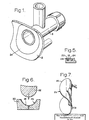
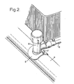
- Figures 1 and 2 of the accompanying illustrative drawings show a known form of tapping saddle in which Figure 1 is a perspective view from below of the tapping saddle, and Figure 2 is a perspective view from above of the tapping saddle connected to a pipe.
- the tapping saddle has a saddle pad 2 of thermoplastics for connection to a main pipe 4, a tubular body 6 leading from the pad 2, and a branch pipe 7 leading from the body 6 for connection to a pipe 8.
- the pipe 4 is the main pipe and the pipe 8 leads to a consumer point such as for example a house.
- a fusion pad part 2a having an electrical heating coil is located in the saddle pad 2.
- This can be achieved by winding a plastics coated wire into a flat spiral, heat sealing this spiral into a single piece that can be curved to the required pipe diameter, and fixing terminals to the two ends of the heat sealed spiral.
- This spiral complete with the terminals, is curved to the required pipe diameter before spiral and terminals are loaded into an injection moulding tool for encapsulation in thermoplastics to form the saddle pad 2 and body 6.
- the plastics coating which encapsulates the wire spiral is used to maintain the correct wire spacing between adjacent ends of the spiral, and also the optimum spacing between the coil and the pipe 4 during welding.
- Our G.B. Patent Specification 2,158,007A discloses a method of producing a fusion pad comprising forming in one surface of a thermoplastics sheet a continuous groove extending between an inner end and an outer end, locating in the groove and electrically conductive wire having a diameter less than the depth of the groove, and melting the upper portion of the groove to envelope and retain the wire in the sheet.
- the two ends of the wire are connected to respective terminals which project from the sheet.
- This fusion pad is then bent into a required curvature (such as a saddle) and is placed in a suitable tool to mould a tapping saddle which includes the fusion pad.
- a required curvature such as a saddle
- the known tapping saddle (including the fusion pad) is fused to the pipe 4 by passing current through the wire in the pad.
- current through the wire in the pad.
- the wire has to heat both the pipe and also the part of the pad behind the wire in order to complete the bond of the pad to the tapping saddle. It has been found that this comparatively long duration current can produce sufficient heat to cause the edges of the saddle pad to lift off the pipe 4 thereby reducing the efficiency of the bond.
- thermoplastics member with a fusion pad
- said pad comprising an element which is to be electrically heated for the purpose of welding the assembly to a surface of compatible thermoplastics material, and which comprises locating the element in an envelope of thermoplastics material to provide the fusion pad; mounting the fusion pad in a plastics moulding machine; moulding the thermoplastics member over the fusion pad and, during the moulding of the thermoplastics member electrically heating the element to assist in bonding the thermoplastics material of the envelope to the material of the member.
- apparatus for moulding an assembly of a thermoplastics member with a fusion pad which comprises a plastics injection moulding machine having a moulding tool with a cavity substantially corresponding to the shape of the assembly which is to be formed; means for mounting in the cavity a fusion pad comprising a thermoplastics envelope and an element which is to be electrically heated located in said envelope; electrical connection means for coupling with the element of a fusion pad mounted in the cavity whereby that pad can be electrically heated, and means controlling electrical heating of the element during moulding of the thermoplastics member to assist in bonding the thermoplastics material of the envelope to that of the member which is moulded in the cavity.
- the assembly can be of any structure which is intended to be electrically welded to a thermoplastics surface.
- the invention will have particular advantage for pipe couplings such as in socket and spigot joints or in pipe tapping saddles or connections as previously mentioned.
- the fusion pad comprising the wire element and thermoplastics envelope can be of many forms, such as a sleeve or tube for moulding into a socket for a pipe coupling or a flat or curved disc for moulding into a tapping saddle as proposed in G.B. 2,158,007A
- thermoplastics envelope of the fusion pad is molten, or substantially so, at its interface with the material (which will usually be injected) for moulding the member and thereby for an efficient bond to be achieved between the two compatible plastics.
- the fusion pad is mounted in the cavity of the moulding machine tool so that a surface part of the envelope (which surface part corresponds to that part of the fusion pad which is to be welded to a compatible thermoplastics surface) communicates (preferably in face-to-face contact) with a wall part of the machine.
- This wall part of the moulding machine can be temperature controlled, for example by electrical heating means and/or fluid heat exchangers, to provide desired moulding conditions for the fusion pad to be bonded to the injected thermoplastics.
- the aforementioned wall part of the tool is temperature controlled to maintain the surface part of the envelope with which it communicates substantially solid.
- the element in the fusion pad may be electrically heated and the moulding conditions controlled to provide a temperature gradient through the material of the envelope so that the surface of the envelope may be molten to bond to the material which is being moulded to form the member.
- the moulding conditions controlled to provide a temperature gradient through the material of the envelope so that the surface of the envelope may be molten to bond to the material which is being moulded to form the member.
- the moulding of the member is likely to be carried out in the range of 200°C to 250°C (although the thermoplastics will usually melt at temperatures above 130°). It is therefore preferred that the aforementioned wall part of the moulding tool is temperature controlled to be less than 130° to provide a required temperature gradient in the envelope as aforementioned.
- the present invention is not limited to any particular amplitude and time duration of current for heating the element, but particularly good results have been obtained when heating a wire element for approximately forty five to sixty seconds with a current of approximately five amps.
- the invention also includes an assembly which is moulded by the method specified as being in accordance with the invention.
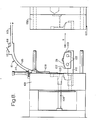
- two terminals 10 and 12 project from the underside of a fusion pad 2b (shown partly formed in Figures 3 and 4) comprising an annular sheet of thermoplastics enveloping material 14 and an electrically conductive wire 16.
- the wire 16 is fed from a reel 18, has one end passed through a hole 20 in the sheet 14 and is secured to the terminal 10.
- the wire 16 emerging from the hole 20 is guided into the inner end of a spiral groove 22 which is formed in the upper surface of the sheet 14.
- the sheet 14 is rotated so as to cause the wire 16 progressively to enter the groove 22.
- the side walls of the groove 22 have a height greater than the diameter of the wire 16 thereby ensuring that the groove walls 24 project above the wire 16 in the groove.
- An electrical heating tool 26 is applied to each part of the groove 22 as soon as the wire 16 is located in that groove part thereby causing the adjacent groove walls 24 to heat up and become molten at their upper regions. These molten upper regions of the groove walls collapse inwardly onto the wire 16 therebetween, and these walls 24 solidify in that position after they emerge from the heating tool 26 so as to envelope and retain the wire 16 in the groove. It will be appreciated from Figure 4 that by rotating the disc-like sheet 14 for a sufficient number of revolutions and causing the heating tool 26 to travel outwardly from the inner to the outer end of the groove 22, then the wire 16 is retained in the entire length of the groove 22. The wire 16 is then fed through a notch 28 in the outer periphery of the sheet 14 and secured to the terminal 12.
- the fusion pad is then located on the forming surface of a tool base 30, and a punch 32 is pressed onto the tool base 30 to shape the fusion pad 2b into required saddle or curvature as illustrated in Figure 7. Because of the previously described technique of retaining the wire 16 in the groove 22, this curving of the fusion pad does not cause the wire 16 to come out of the groove 22.
- the fusion pad 2b as shown in Figure 7 is now assembled as part of a tapping saddle by moulding it into a thermoplastics body to provide a structure which may be regarded as similar to that shown in Figure 1 with the pad 2b corresponding to the pad part 2a.
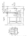
- This assembly is achieved by use of an injection moulding machine having a split cavity moulding tool 100 ( Figures 8 and 10) with die parts 101, 102 and a base part 103.
- the moulding tool 100 when closed for injection moulding (as shown in Figure 10) has a moulding cavity 104 which substantially corresponds to the profile of the tapping saddle shown in Figure 1 and, in conventional manner, retractable rods 108, 109 are provided in the tool which correspond to required bores which are to be formed in the saddle.
- the cavity 104 in the mould when closed is defined by appropriately shaped recesses 105, 106 in the die parts and a convex surface 107 on the base part 3.
- the convex surface 107 corresponds to the concave profile of the fusion pad 2b and such a pad 2b is mounted in the tool with its concave surface in face-to-face contact with the surface 107 as shown in Figure 8.
- the base part 103 is carried by a linkage 110 which extends when the tool 100 is opened to locate the base part 103 clear of the two die parts and retracts as the die parts are closed to define the cavity 104 - this linkage 110 also serves as an ejector for convenience of removing the moulded tapping saddle from the moulding tool.
- an electrical control system 111 having an on/off control switch 112 for a power supply 113 for electrically heating the wire element 16 in the fusion pad 2b.
- the system 111 includes electrical conduits 114 and 115 which extend through passages in the moulding tool to communicate with terminals 116 and 117 respectively.
- the terminals 116 and 117 are displaceable in the moulding tool and are located to correspond (see Figure 9) with the terminals 10 and 12 respectively of the fusion pad 2b which is mounted on the base part 103.
- Displacement of the terminals 116 and 117 is conveniently achieved by their movement in unison with the rod 109 so that, as the moulding tool is closed, the terminals 116 and 117 are automatically moved into electrical engagement with the respective terminals 10 and 12 and an electrical connection is thereby provided between the wire heating element and the system 111.
- the system 111 conveniently includes a timer device 118 which is actuated on closing the switch 112 to electrically heat the wire element 16 for a predetermined period.
- the tool 100 On moulding the tapping saddle the tool 100 is closed around a fusion pad 2b mounted on the base part 103 to effect the electrical connection between the terminals 10 and 12 and the electrical system 111 and the switch 112 is closed to electrically heat the wire element 16 in the fusion pad.
- the cavity 104 is charged with thermoplastics in conventional manner from an injector device 119 of the machine to mould the body 120 over the fusion pad 2b as shown in Figure 10 during which a removable sprue 121 is formed.
- thermoplastics are suitable for producing the envelope of the fusion pad and the body of the tapping saddle provided that these plastics are compatible for bonding together as aforementioned; a preferred thermoplastics is medium or high density polyethylene and for this the saddle body 120 is moulded in a temperature range of approximately 200°C to 250°C.
- a preferred thermoplastics is medium or high density polyethylene and for this the saddle body 120 is moulded in a temperature range of approximately 200°C to 250°C.
- the surface of the envelope which bonds to the injected plastics is molten as a result of the heating effect from the wire element 16.
- the concave surface of the envelope which is in face-to-face contact with the base part 103 of the moulding tool is maintained solid (or substantially so).
- the wire element 16 will usually be located relatively near to the concave surface of the fusion pad 2b (to ensure that there will be an adequate transfer of heat from the fusion pad to a pipe surface to which the moulded saddle will ultimately be welded) and, by locating the wire element 16 in a region of the thermoplastics envelope 14 which is maintained relatively solid during injection moulding of the saddle body 120, it is possible to alleviate disturbance of the position of the wire element 16 in the fusion pad during the moulding process.
- the base part 103 includes temperature control means such as passages 122 through which fluid, typically water, can flow for the purpose of heating or cooling that base part and thereby maintaining its surface 107 at a temperature consistent with the concave surface of the fusion pad being maintained solid during the moulding process.
- fluid typically water
- the temperature of the surface 107 will usually be maintained at less than 130°C.
- the fusion pad envelope 14 typically, will have a thickness in the range of 0.5 millimetres to 2.0 millimetres and applying the moulding characteristics as aforementioned to such a pad, efficient fusing or bonding of the fusion pad to the injection moulded saddle body has been achieved with a current of approximately 5 amps being passed through the heating element 16 for approximately 45 to 50 seconds.
- the invention can be applied to a pipe coupling in which case an appropriate moulding tool is provided having a cavity corresponding to the external profile of the coupling which is to be injection moulded while the bore of the coupling may be defined by a cylindrical rod core which extends through the cavity and on which is mounted a tubular fusion pad so that terminals on the fusion pad element contact with an electrical control system similar to that previously discussed.
- the rod core is preferably temperature controlled in a similar manner to the base part 103 and for a similar purpose.
Landscapes
- Engineering & Computer Science (AREA)
- Mechanical Engineering (AREA)
- General Engineering & Computer Science (AREA)
- Manufacturing & Machinery (AREA)
- Chemical & Material Sciences (AREA)
- Composite Materials (AREA)
- Lining Or Joining Of Plastics Or The Like (AREA)
- Branch Pipes, Bends, And The Like (AREA)
Applications Claiming Priority (2)
| Application Number | Priority Date | Filing Date | Title |
|---|---|---|---|
| GB868606790A GB8606790D0 (en) | 1986-03-19 | 1986-03-19 | Thermoplastics member |
| GB8606790 | 1986-03-19 |
Publications (2)
| Publication Number | Publication Date |
|---|---|
| EP0238239A2 true EP0238239A2 (de) | 1987-09-23 |
| EP0238239A3 EP0238239A3 (de) | 1990-02-07 |
Family
ID=10594877
Family Applications (1)
| Application Number | Title | Priority Date | Filing Date |
|---|---|---|---|
| EP87301989A Withdrawn EP0238239A3 (de) | 1986-03-19 | 1987-03-09 | Verfahren und Vorrichtung zum Formen eines thermoplastischen Gegenstandes mit einem Schweisseinsatz |
Country Status (4)
| Country | Link |
|---|---|
| US (1) | US4806181A (de) |
| EP (1) | EP0238239A3 (de) |
| AU (1) | AU603353B2 (de) |
| GB (2) | GB8606790D0 (de) |
Cited By (1)
| Publication number | Priority date | Publication date | Assignee | Title |
|---|---|---|---|---|
| DE102004023338A1 (de) * | 2004-05-12 | 2005-12-15 | Gwc Gas-Water-Valves-Components Gmbh | Heizvorrichtung zum Verschweißen von mindestens zwei aus einem Kunststoffmaterial bestehenden Gegenständen |
Families Citing this family (9)
| Publication number | Priority date | Publication date | Assignee | Title |
|---|---|---|---|---|
| GB2238011A (en) * | 1989-11-18 | 1991-05-22 | Crystalate Electronics | Moulding composite articles |
| US5820719A (en) * | 1997-01-28 | 1998-10-13 | Worthen Industries, Inc. | Method for forming a sole having a heat activatable adhesive adhered to one side thereof for subsequent attachment to an upper |
| GB2421553A (en) | 2004-12-23 | 2006-06-28 | Uponor Innovation Ab | Tapping tee assembly with an integrated cutter and dual electrofusion elements |
| GB2422348A (en) | 2005-01-25 | 2006-07-26 | Uponor Innovation Ab | Joining metal to plastic with heat activated adhesive |
| GB2426306A (en) | 2005-05-18 | 2006-11-22 | Uponor Innovation Ab | Tapping tee with flexible spigot |
| GB2451080B (en) * | 2007-07-17 | 2011-10-05 | Uponor Innovation Ab | Tapping tee assembly |
| GB2453569B (en) | 2007-10-11 | 2012-04-25 | Radius Systems Ltd | Purge tee assembley |
| DK2902172T3 (en) | 2014-01-30 | 2018-06-14 | Plasson Ltd | ELECTROFUSION CONNECTOR PART AND PROCESS FOR MANUFACTURING ELECTROFUSION CONNECTOR PART |
| ES2668773T3 (es) | 2014-01-30 | 2018-05-22 | Plasson Ltd | Miembro de acoplamiento de electrofusión y proceso de fabricación de miembro de acoplamiento de electrofusión |
Family Cites Families (10)
| Publication number | Priority date | Publication date | Assignee | Title |
|---|---|---|---|---|
| US3183361A (en) * | 1959-08-07 | 1965-05-11 | Texas Instruments Inc | Method of making glass sealed electric circuit devices and article resulting therefrom |
| CH528697A (de) * | 1972-02-08 | 1972-09-30 | Rollmaplast Ag Kunststoffrohr | Elektrisch schweissbares Anbohrformstück aus thermoplastischem Werkstoff |
| NL175458C (nl) * | 1973-03-14 | 1984-11-01 | Sturm Werner | Werkwijze voor het vervaardigen van een lasmof voor thermoplastische buizen. |
| FR2519578A1 (fr) * | 1981-07-01 | 1983-07-18 | Sam Innovation Tech | Dispositif en matiere plastique pour realiser une perforation dans un element sous-jacent en matiere plastique, procede de fabrication d'un tel dispositif et sa mise en oeuvre pour realiser des derivations de canalisations |
| CH652473A5 (de) * | 1981-10-02 | 1985-11-15 | Fischer Ag Georg | Schweissverbindung fuer kunststoffrohre. |
| AU569278B2 (en) * | 1983-03-09 | 1988-01-28 | Rutland Plastics Ltd. | Weldable thermoplastic pipe fitting |
| GB2137297B (en) * | 1983-03-30 | 1986-11-26 | Fusion Plastics Ltd | Branch pipe fitting for thermoplastic pipe |
| FR2558326B1 (fr) * | 1983-12-07 | 1986-06-27 | Rech Applic Plastiques Et | Raccord de branchement en charge, resistance electrique pour un tel raccord et son procede de fabrication |
| SE451557B (sv) * | 1984-02-29 | 1987-10-19 | Fiber Mech | Sett och anordning for tillverknig av en kropp av fiberarmerad plast, varvid elstrom ledes genom fibrerna i samband med lindningsoperationen |
| GB8410765D0 (en) * | 1984-04-27 | 1984-06-06 | Glynwed Tubes & Fittings | Fusion pad |
-
1986
- 1986-03-19 GB GB868606790A patent/GB8606790D0/en active Pending
-
1987
- 1987-03-04 US US07/021,446 patent/US4806181A/en not_active Expired - Fee Related
- 1987-03-09 EP EP87301989A patent/EP0238239A3/de not_active Withdrawn
- 1987-03-09 GB GB8705467A patent/GB2187998B/en not_active Expired
- 1987-03-18 AU AU70135/87A patent/AU603353B2/en not_active Expired - Fee Related
Cited By (1)
| Publication number | Priority date | Publication date | Assignee | Title |
|---|---|---|---|---|
| DE102004023338A1 (de) * | 2004-05-12 | 2005-12-15 | Gwc Gas-Water-Valves-Components Gmbh | Heizvorrichtung zum Verschweißen von mindestens zwei aus einem Kunststoffmaterial bestehenden Gegenständen |
Also Published As
| Publication number | Publication date |
|---|---|
| GB8705467D0 (en) | 1987-04-15 |
| GB8606790D0 (en) | 1986-04-23 |
| GB2187998A (en) | 1987-09-23 |
| US4806181A (en) | 1989-02-21 |
| EP0238239A3 (de) | 1990-02-07 |
| GB2187998B (en) | 1989-12-06 |
| AU603353B2 (en) | 1990-11-15 |
| AU7013587A (en) | 1987-09-24 |
Similar Documents
| Publication | Publication Date | Title |
|---|---|---|
| US4894521A (en) | Electric heating element for fusing thermoplastic materials | |
| US5375889A (en) | Electrofusion joint and hot water supply header using the same | |
| US3788928A (en) | Method of forming a lap joint between tubular articles of thermoplastic material | |
| US4806181A (en) | Method for moulding a thermoplastics member with a fusion pad | |
| EP0055891B1 (de) | Verfahren zur Herstellung eines durch Hitze abdichtbaren Anschluss-Stückes | |
| US4684428A (en) | Method of making a fusion pad | |
| EP0695624B1 (de) | Tankanschlussteilkonstruktion | |
| US5238615A (en) | Method for joining together of tubular plastic products | |
| JPH0739120B2 (ja) | 溶着継手の製造方法 | |
| JPH02270536A (ja) | 溶融性プラスチツク材料の物理的状態変化検知装置 | |
| US5431764A (en) | Method of fabricating a tank and method of fabricating a tank connector therefor | |
| GB2137297A (en) | Branch pipe fitting for thermoplastic pipe | |
| JPS6259655B2 (de) | ||
| JP2721465B2 (ja) | 電気融着式プラスチック管継手 | |
| JP5856672B2 (ja) | 管状の片受け電気融着継手及びその製造方法 | |
| JP3136027B2 (ja) | 受口付プラスチックパイプの成形方法 | |
| JP4574881B2 (ja) | 電気融着継手の製造方法 | |
| JP2709363B2 (ja) | プラスチックパイプの製造方法 | |
| JPH07151289A (ja) | 電気融着継手 | |
| JP3224855B2 (ja) | 電熱コイルが埋設された受口を有する合成樹脂管の製法 | |
| JPH11315987A (ja) | 予備成形体及び電気融着継手の製法 | |
| JPS5882742A (ja) | プラスチツク容器の製造方法 | |
| JPH09126378A (ja) | 電気融着式分岐継手の製造方法 | |
| JPS63203317A (ja) | フランジ部を有するフツ素樹脂製管体の製造方法 | |
| JPH09229280A (ja) | 2層融着用管継手および2層融着用管継手の製造方法 |
Legal Events
| Date | Code | Title | Description |
|---|---|---|---|
| PUAI | Public reference made under article 153(3) epc to a published international application that has entered the european phase |
Free format text: ORIGINAL CODE: 0009012 |
|
| AK | Designated contracting states |
Kind code of ref document: A2 Designated state(s): BE DE FR IT NL |
|
| PUAL | Search report despatched |
Free format text: ORIGINAL CODE: 0009013 |
|
| AK | Designated contracting states |
Kind code of ref document: A3 Designated state(s): BE DE FR IT NL |
|
| 17P | Request for examination filed |
Effective date: 19900228 |
|
| 17Q | First examination report despatched |
Effective date: 19900828 |
|
| STAA | Information on the status of an ep patent application or granted ep patent |
Free format text: STATUS: THE APPLICATION IS DEEMED TO BE WITHDRAWN |
|
| 18D | Application deemed to be withdrawn |
Effective date: 19911007 |
|
| RIN1 | Information on inventor provided before grant (corrected) |
Inventor name: EWEN, ALEXANDER THOMAS EDMUND Inventor name: HEWITT, DAVID ANTHONY |