EP0237814B1 - Ventilanordnung - Google Patents
Ventilanordnung Download PDFInfo
- Publication number
- EP0237814B1 EP0237814B1 EP87102253A EP87102253A EP0237814B1 EP 0237814 B1 EP0237814 B1 EP 0237814B1 EP 87102253 A EP87102253 A EP 87102253A EP 87102253 A EP87102253 A EP 87102253A EP 0237814 B1 EP0237814 B1 EP 0237814B1
- Authority
- EP
- European Patent Office
- Prior art keywords
- valve
- stem
- valve stem
- seat
- valve seat
- Prior art date
- Legal status (The legal status is an assumption and is not a legal conclusion. Google has not performed a legal analysis and makes no representation as to the accuracy of the status listed.)
- Expired
Links
- 238000002485 combustion reaction Methods 0.000 claims abstract description 25
- 230000001154 acute effect Effects 0.000 claims description 3
- 230000001419 dependent effect Effects 0.000 claims description 3
- 230000006835 compression Effects 0.000 description 15
- 238000007906 compression Methods 0.000 description 15
- 230000008859 change Effects 0.000 description 4
- 238000004939 coking Methods 0.000 description 2
- 238000010276 construction Methods 0.000 description 2
- 238000000034 method Methods 0.000 description 2
- 230000008569 process Effects 0.000 description 2
- 238000007789 sealing Methods 0.000 description 2
- 230000009471 action Effects 0.000 description 1
- 230000005540 biological transmission Effects 0.000 description 1
- 230000003197 catalytic effect Effects 0.000 description 1
- 239000000919 ceramic Substances 0.000 description 1
- 230000009849 deactivation Effects 0.000 description 1
- 230000000694 effects Effects 0.000 description 1
- 238000002347 injection Methods 0.000 description 1
- 239000007924 injection Substances 0.000 description 1
- 239000011810 insulating material Substances 0.000 description 1
- 230000007774 longterm Effects 0.000 description 1
- 238000011089 mechanical engineering Methods 0.000 description 1
- 230000005226 mechanical processes and functions Effects 0.000 description 1
- 239000000203 mixture Substances 0.000 description 1
- 238000013386 optimize process Methods 0.000 description 1
- 238000004886 process control Methods 0.000 description 1
- 230000009467 reduction Effects 0.000 description 1
- 230000000284 resting effect Effects 0.000 description 1
Images
Classifications
-
- F—MECHANICAL ENGINEERING; LIGHTING; HEATING; WEAPONS; BLASTING
- F02—COMBUSTION ENGINES; HOT-GAS OR COMBUSTION-PRODUCT ENGINE PLANTS
- F02D—CONTROLLING COMBUSTION ENGINES
- F02D15/00—Varying compression ratio
- F02D15/04—Varying compression ratio by alteration of volume of compression space without changing piston stroke
-
- F—MECHANICAL ENGINEERING; LIGHTING; HEATING; WEAPONS; BLASTING
- F01—MACHINES OR ENGINES IN GENERAL; ENGINE PLANTS IN GENERAL; STEAM ENGINES
- F01L—CYCLICALLY OPERATING VALVES FOR MACHINES OR ENGINES
- F01L1/00—Valve-gear or valve arrangements, e.g. lift-valve gear
- F01L1/28—Valve-gear or valve arrangements, e.g. lift-valve gear characterised by the provision of coaxial valves; characterised by the provision of valves co-operating with both intake and exhaust ports
-
- F—MECHANICAL ENGINEERING; LIGHTING; HEATING; WEAPONS; BLASTING
- F01—MACHINES OR ENGINES IN GENERAL; ENGINE PLANTS IN GENERAL; STEAM ENGINES
- F01L—CYCLICALLY OPERATING VALVES FOR MACHINES OR ENGINES
- F01L3/00—Lift-valve, i.e. cut-off apparatus with closure members having at least a component of their opening and closing motion perpendicular to the closing faces; Parts or accessories thereof
- F01L3/20—Shapes or constructions of valve members, not provided for in preceding subgroups of this group
-
- F—MECHANICAL ENGINEERING; LIGHTING; HEATING; WEAPONS; BLASTING
- F01—MACHINES OR ENGINES IN GENERAL; ENGINE PLANTS IN GENERAL; STEAM ENGINES
- F01L—CYCLICALLY OPERATING VALVES FOR MACHINES OR ENGINES
- F01L7/00—Rotary or oscillatory slide valve-gear or valve arrangements
- F01L7/10—Rotary or oscillatory slide valve-gear or valve arrangements with valves of other specific shape, e.g. spherical
-
- F—MECHANICAL ENGINEERING; LIGHTING; HEATING; WEAPONS; BLASTING
- F02—COMBUSTION ENGINES; HOT-GAS OR COMBUSTION-PRODUCT ENGINE PLANTS
- F02B—INTERNAL-COMBUSTION PISTON ENGINES; COMBUSTION ENGINES IN GENERAL
- F02B19/00—Engines characterised by precombustion chambers
- F02B19/02—Engines characterised by precombustion chambers the chamber being periodically isolated from its cylinder
-
- F—MECHANICAL ENGINEERING; LIGHTING; HEATING; WEAPONS; BLASTING
- F02—COMBUSTION ENGINES; HOT-GAS OR COMBUSTION-PRODUCT ENGINE PLANTS
- F02B—INTERNAL-COMBUSTION PISTON ENGINES; COMBUSTION ENGINES IN GENERAL
- F02B1/00—Engines characterised by fuel-air mixture compression
- F02B1/02—Engines characterised by fuel-air mixture compression with positive ignition
- F02B1/04—Engines characterised by fuel-air mixture compression with positive ignition with fuel-air mixture admission into cylinder
Definitions
- the invention relates to a valve arrangement for mechanical devices with a valve, in particular for an internal combustion engine, which has a valve stem and a valve disk arranged at an acute angle thereto and which can be lifted off an associated valve seat.
- the conventional plate valves have a circular plate, the plane of which forms a right angle to the valve stem, the valve plate resting on a frustoconical seat in the closed state.
- this valve design results in a high flow resistance due to the annular opening gap.
- JP 60-6010 a valve arrangement with a generic valve with arrangement of the valve plate at a predetermined angle to the valve stem is known. As a result, the efficiency of the intake and exhaust process can be increased by reducing the flow resistance.
- JP 55-8407 it is known to equip a valve disk with a beveled hollow cylinder, to which an opposing valve seat is assigned.
- the round valve disc can be rotated around its axis, whereby the opening time can be reduced depending on the rotational position.
- the object of the invention is to provide a valve arrangement with which a compression chamber can be connected to secondary chambers or channels by opening and closing a valve, in particular in order to achieve a variable compression ratio.
- valve assembly is characterized in that the valve plate is not circular and this sits in the truncated cone-shaped valve seat, the height of which is determined by the angle between the valve stem and valve plate, sealingly in the closed state and in the lifted-off state can be rotated or swung back and forth about its valve stem via a swivel drive so that chambers or channels that open into the valve seat can be opened and closed.
- the swivel drive can work back and forth or in the same direction.
- valve plate is elliptical and is eccentric to the valve stem.
- the swivel drive can be controlled according to the clock and / or dependent on a computer.
- valve seat in which the valve disc lies as an oblique conical section, centered or eccentric to the valve stem.
- the known flow resistance only results from the oscillating movement, while in the phase of rotation of a partial circle rotation a chamber or channel opening in the frustoconical valve seat can be opened or closed without a cross section. After turning back, the valve plate sits on its seat; this results in a wide range of uses.
- the valve according to the invention can be used to implement a gradual change in the compression ratio in variable-volume internal combustion engines. will.
- the change in the compression ratio is made possible by the fact that an auxiliary chamber is assigned to the valve, which opens into the seat of the valve.
- the auxiliary chamber is closed by turning the valve, which increases the compression ratio.
- the secondary chamber is opened by turning the valve, so that the reduced compression ratio prevents knocking combustion.
- the need to open or close the secondary chamber is indicated, for example, by the throttle valve position or the start of knocking, recorded by sensors and processed in a computer with other suitable sensor data.
- the pitch circle rotation of the valve then takes place with the aid of a computer-controlled signal box.
- the gas forces are introduced directly into the cylinder head via the valve plate and the valve seat in the working phase.
- the signal box remains unused.
- a coking of functionally important sealing surfaces is prevented because the valve keeps the sealing surfaces free by oscillating and controlled turning.
- valve according to the invention with an associated secondary chamber can also be used for process-specific compression reduction or compression increase in self-igniting, in particular highly charged, internal combustion engines - diesel engines.
- the opening and closing of the secondary chamber takes place, for example, in a pressure or quantity-controlled manner.
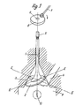
- the valve according to the invention consists of the valve stem 1 with an elliptical valve plate 2, the The plate plane EE forms an acute angle to the valve stem 1 and which is arranged in an oscillating and / or rotating manner in the valve seat 3 and thus serves to open or close the secondary chamber 4, as shown here.
- the valve seat 3 is formed by the inner wall of a truncated cone, in which the valve plate 2 is eccentric to the valve stem 1 as an oblique conical section.
- valve stem is non-positively connected in the end region at the valve stem end 5, here by an oval design with a swivel drive in the form of a rotary crank wheel 6 with an engaging rotating arm 7, which (6) with the oval perforation 8 can be placed on the oval valve stem end 5 so that it can be pushed in a courtly manner.
- the height is adjusted in a known manner by means of a camshaft against the action of the valve spring, as can then be seen in FIG. 5.
- the valve seat 3 is followed by the cylinder chamber 9 with spark ignition 10, the secondary chamber 4 being able to be opened and closed above the valve plate 2, as shown in dash-dotted lines.
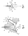
- a valve with valve stem 11 and valve plate 12 the latter is shown as an oblique conical section in the frustoconical valve seat 13 for opening and closing the secondary chamber 14 in the manner described above.
- the valve guide 15 and the exhaust gas duct 16 at the valve seat 13 are also shown here.
- the spark plug 18 is provided in the combustion chamber 17 and, in addition, a spark plug 19 with an injection nozzle 19a in the secondary chamber 14.
- This design is to be driven in the lean operation with the auxiliary chamber 14 activated and in whole or in part with the secondary chamber 14 in the stratified charge operation. Limited load ranges make finishing loading easier.
- the high compression phase results in improved thermodynamic efficiency compared to conventional designs.
- these embodiments can be run with a lean concept.
- Two-stage and multi-stage compression ratios facilitate operation in a lean mixture thanks to high compression and increased turbulence in the combustion chamber.
- the secondary chamber 14 is to be lined with heat-insulating material 20, preferably ceramic.
- This design is intended for two and multi-stage compression ratios. If the basic compression is low, the starting security can be increased and the combustion chamber volume can be adapted to the load by controlling the secondary chamber 14 or the secondary chambers. In the area of use of the ramp-up charge and the cylinder deactivation, this construction seems mechanically and thermodynamically interesting.
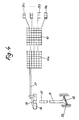
- valve 3 also shows a valve with valve stem 21 and valve plate 22, as well as the main channel as valve seat 23, the secondary channels 24 and 25 being able to be opened and closed to the main channel 26.
- valve according to the invention can also be used in the inlet and / or outlet area of internal combustion engines and in general mechanical engineering for the cross-sectional opening and closing of chambers and channels. This shows the range of possible applications.
- valve stem 31 with valve disk 32 and valve seat 33 is shown schematically in FIG. 4, the valve stem end 35 being connectable to the engaging rotating arms 37 via the attachable crank wheel 36 and the rotary drive in turn being coupled to the oval valve stem 35 via the oval perforation 38 is.
- the entire rotary system is shown schematically here with sensors 39 a-x.
- the knock sensor 39a gives the information for reducing the compression to the computer 40; this (40) then forwards the pulse to the signal box 40a.
- the signal box 40a effects the required partial circle rotation of the valve plate 32, as described at the beginning.
- the sensor 39b for the throttle valve position can, for example, initiate the pulse for increasing the compression in a corresponding manner.
- other sensors up to 39x are to be provided for suitable engine control, e.g. for temperatures, pressures, quantities and load conditions.
- Programs for starting and emergency running can be fed into the computer 40, which can be integrated into a central computer. These programs relate to the mechanical function and functional reliability of the internal combustion engine.
- the valve 40a can be used to rotate the valve by a few angular degrees, for example depending on time intervals. This program has no influence on the process control. Coking of the valve seat is prevented by the normal load change and the necessary turning of the valve.
- a short-term load change can be indicated or initiated using a suitable signal program.
- the program can relate continuously to individual combustion chambers or simultaneously to the entire internal combustion engine.
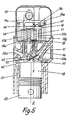
- valve stem 41 with valve plate 42 and valve seat 43, as well as the secondary chamber 44 which can be opened and closed, and at the end of the valve stem 45 the rotating crank wheel 46 with rotating arm 47, the rotary connection again being effected via an oval perforation 48.
- Spark plug 50 is located in combustion chamber 49, for example of a four-stroke internal combustion engine.
- the combustion chamber 49 in the cylinder block 51 with pistons 52 can be seen, the latter limiting the volume of the combustion chamber downwards.
- the cylinder head 51a there are, for example, an intake valve 53, an exhaust valve, not shown, and the valve 41, 42 according to the invention.
- the cylinder longitudinal axis “Z” and the valve stem longitudinal axis “V” of the valve 41, 42 according to the invention are parallel. These axes can also be at an angle so that the partial circular rotation of the valve 41, 42 by a camshaft 57, Transmission elements and / or an interlocking 40a with a corresponding angular position V / Z causes a temporary overlap of the valve plate.
- the valves are assigned the usual control devices, which for the intake valve 53, the exhaust valve (not shown) and the valve 41, 42 according to the invention include, for example, oscillating levers 54a-54x and valve springs 55a-55x. Lift heights and valve spring strengths are different for valves which control the gas exchange and a valve according to the invention which controls only the secondary chamber 44.
- the valve spring 55b is seated on a rotary bearing 56. The valves are actuated via a common camshaft 57.
- the rotation of the valve 41, 42 should take place at low pressure in the combustion chamber 49, preferably with the inlet valve 53 open or the outlet valve not shown. Furthermore, the rotation can be facilitated by a ball bearing 56 below the valve spring 55b.
- the rotary crank 46, 47 rests on the abutments 58a-58x and is held by them.
- the valve 41, 42 is slightly lifted off the valve seat 43 before the pitch circle rotation. This measure increases the service life of the valve and the valve seat surface.
- valve 41, 42 according to the invention can also be used to control an inlet channel 53a and an unillustrated outlet channel or of inlet and / or outlet channels and the associated secondary chambers. If two or more valves according to the invention are connected by a connecting linkage, the number of signal boxes is reduced.
Landscapes
- Engineering & Computer Science (AREA)
- Mechanical Engineering (AREA)
- General Engineering & Computer Science (AREA)
- Combustion & Propulsion (AREA)
- Geometry (AREA)
- Chemical & Material Sciences (AREA)
- Physics & Mathematics (AREA)
- Output Control And Ontrol Of Special Type Engine (AREA)
- Valve-Gear Or Valve Arrangements (AREA)
- Valve Device For Special Equipments (AREA)
- Magnetically Actuated Valves (AREA)
- Combustion Methods Of Internal-Combustion Engines (AREA)
- Lift Valve (AREA)
- Superconductors And Manufacturing Methods Therefor (AREA)
- Valve Housings (AREA)
- Temperature-Responsive Valves (AREA)
- Electrically Driven Valve-Operating Means (AREA)
- Fertilizing (AREA)
- Pens And Brushes (AREA)
Priority Applications (1)
| Application Number | Priority Date | Filing Date | Title |
|---|---|---|---|
| AT87102253T ATE48889T1 (de) | 1986-03-08 | 1987-02-17 | Ventilanordnung. |
Applications Claiming Priority (2)
| Application Number | Priority Date | Filing Date | Title |
|---|---|---|---|
| DE3607798 | 1986-03-08 | ||
| DE19863607798 DE3607798A1 (de) | 1986-03-08 | 1986-03-08 | Ventilanordnung |
Publications (2)
| Publication Number | Publication Date |
|---|---|
| EP0237814A1 EP0237814A1 (de) | 1987-09-23 |
| EP0237814B1 true EP0237814B1 (de) | 1989-12-20 |
Family
ID=6295907
Family Applications (1)
| Application Number | Title | Priority Date | Filing Date |
|---|---|---|---|
| EP87102253A Expired EP0237814B1 (de) | 1986-03-08 | 1987-02-17 | Ventilanordnung |
Country Status (9)
| Country | Link |
|---|---|
| US (1) | US4739968A (enExample) |
| EP (1) | EP0237814B1 (enExample) |
| JP (1) | JPS62253919A (enExample) |
| KR (1) | KR900007812B1 (enExample) |
| AT (1) | ATE48889T1 (enExample) |
| BR (1) | BR8701366A (enExample) |
| DE (1) | DE3607798A1 (enExample) |
| ES (1) | ES2012366B3 (enExample) |
| GR (1) | GR3000262T3 (enExample) |
Families Citing this family (11)
| Publication number | Priority date | Publication date | Assignee | Title |
|---|---|---|---|---|
| ES2158801B1 (es) * | 1999-09-14 | 2002-03-16 | Martinez Luis Enrique Bonet | Culata de valvulas elipticas de movimiento compuesto. |
| DE19950682A1 (de) | 1999-10-21 | 2001-04-26 | Volkswagen Ag | Verfahren zum Betreiben einer zumindest einen Arbeitskolben aufweisenden Brennkraftmaschine |
| DE19950677A1 (de) * | 1999-10-21 | 2001-04-26 | Volkswagen Ag | Verfahren zum Betreiben einer zumindest einen in einem Zylinder geführten Arbeitskolben aufweisenden Brennkraftmaschine |
| US6679219B1 (en) * | 2000-02-23 | 2004-01-20 | Louis A. Pacinelli | Intake and exhaust valves for internal combustion engines |
| DE10311229B4 (de) * | 2003-03-14 | 2005-03-31 | Iav Gmbh Ingenieurgesellschaft Auto Und Verkehr | Verbrennungsmotor mit veränderbarem Verdichtungsverhältnis |
| US6817326B1 (en) | 2003-09-22 | 2004-11-16 | Kevin J. Anibas | Valve system for internal combustion engines |
| US7779807B2 (en) * | 2003-11-11 | 2010-08-24 | Honda Motor Co., Ltd. | Intake/exhaust valve and its seal for internal combustion engine |
| FR2979967B1 (fr) * | 2011-09-13 | 2014-10-03 | Peugeot Citroen Automobiles Sa | Dispositif comportant un clapet associe a un conduit et ensemble de motorisation comprenant un tel dispositif |
| FR2979965B1 (fr) * | 2011-09-13 | 2014-10-10 | Peugeot Citroen Automobiles Sa | Dispositif comportant un clapet associe a un conduit et ensemble de motorisation comprenant un tel dispositif |
| FR2979966B1 (fr) * | 2011-09-13 | 2014-10-03 | Peugeot Citroen Automobiles Sa | Dispositif comportant un clapet associe a un conduit et ensemble de motorisation comprenant un tel dispositif |
| WO2013061060A1 (en) * | 2011-10-24 | 2013-05-02 | Wyatt Gary John | Poppet valve assemblies |
Family Cites Families (12)
| Publication number | Priority date | Publication date | Assignee | Title |
|---|---|---|---|---|
| US3126193A (en) * | 1964-03-24 | atherton | ||
| GB190909354A (en) * | 1909-04-20 | 1910-01-20 | Charles Henry Whittington | Improved Means for Varying the Compression Space in Internal Combustion Engines. |
| CH225425A (de) * | 1942-08-05 | 1943-01-31 | Bachmann Henri | Einrichtung an Verbrennungskraftmaschinen zum Regeln des Kompressionsdruckes. |
| DE1043708B (de) * | 1952-12-04 | 1958-11-13 | Moteurs Goiot | Gemischverdichtende Zweitakt-Brennkraftmaschine |
| US3051156A (en) * | 1960-10-24 | 1962-08-28 | Aspin Frank Metcalf | Internal combustion engines, compressors and the like |
| JPS5584807A (en) * | 1978-12-18 | 1980-06-26 | Nissan Motor Co Ltd | Arrangement for valve used in internal-combustion engine |
| DE2916509A1 (de) * | 1979-04-24 | 1980-11-06 | Friedhelm Herzog | Kombinierte ventil-schieber-steuerung |
| EP0092869A3 (en) * | 1982-04-23 | 1984-02-22 | Van de Vel, Alfons Juul | Improved motor |
| JPS59529A (ja) * | 1982-06-24 | 1984-01-05 | Toshie Kobayashi | 予燃焼室を生滅するエンヂン |
| US4562993A (en) * | 1982-08-31 | 1986-01-07 | Lew Hyok S | Dual action handle for floating disc valve and ball-plug valve |
| JPS606010A (ja) * | 1983-06-25 | 1985-01-12 | Mitsubishi Heavy Ind Ltd | 往復動機関の給,排気弁 |
| DE3433380A1 (de) * | 1984-09-12 | 1986-03-20 | Ulrich 2000 Norderstedt Becker | Einlasswinkelventil zur steuerung der schichtladung des ottomotors |
-
1986
- 1986-03-08 DE DE19863607798 patent/DE3607798A1/de active Granted
-
1987
- 1987-02-13 US US07/014,284 patent/US4739968A/en not_active Expired - Lifetime
- 1987-02-17 EP EP87102253A patent/EP0237814B1/de not_active Expired
- 1987-02-17 ES ES87102253T patent/ES2012366B3/es not_active Expired - Lifetime
- 1987-02-17 AT AT87102253T patent/ATE48889T1/de active
- 1987-03-05 BR BR8701366A patent/BR8701366A/pt not_active IP Right Cessation
- 1987-03-07 KR KR1019870002060A patent/KR900007812B1/ko not_active Expired
- 1987-03-09 JP JP62053915A patent/JPS62253919A/ja active Granted
-
1989
- 1989-12-21 GR GR89400254T patent/GR3000262T3/el unknown
Also Published As
| Publication number | Publication date |
|---|---|
| KR870009110A (ko) | 1987-10-23 |
| ES2012366B3 (es) | 1990-03-16 |
| DE3607798C2 (enExample) | 1987-12-03 |
| ATE48889T1 (de) | 1990-01-15 |
| US4739968A (en) | 1988-04-26 |
| GR3000262T3 (en) | 1991-03-15 |
| JPS62253919A (ja) | 1987-11-05 |
| KR900007812B1 (ko) | 1990-10-20 |
| BR8701366A (pt) | 1987-12-22 |
| JPH0432215B2 (enExample) | 1992-05-28 |
| DE3607798A1 (de) | 1987-09-10 |
| EP0237814A1 (de) | 1987-09-23 |
Similar Documents
| Publication | Publication Date | Title |
|---|---|---|
| DE19922600B4 (de) | Brennkraftmaschine mit variabler Nockenwellen-Synchronisation und mit einer Auslaßphase variabler Dauer | |
| DE19922568C2 (de) | Brennkraftmaschine mit variabler Nockenwellen-Synchronisation, einem Regelventil für die Ladungsbewegung und variablem Luft/Kraftstoff-Verhältnis | |
| EP0237814B1 (de) | Ventilanordnung | |
| DE2324190A1 (de) | Verfahren zum betreiben einer brennkraftmaschine und nach diesem verfahren arbeitende brennkraftmaschine | |
| DE3424773A1 (de) | Brennkraftmaschine mit einer einzigen obenliegenden nockenwelle | |
| DE102004030452A1 (de) | Verfahren und Vorrichtung zum Betreiben einer Brennkraftmaschine | |
| DE3650636T2 (de) | Ventilantriebmechanismus für Brennkraftmaschine | |
| EP1697624A1 (de) | Verfahren und vorrichtung zum steuern einer brennkraftmaschine | |
| EP1840352B1 (de) | Frischgasanlage und Betriebsverfahren für einen Kolbenmotor | |
| DE102022125505B4 (de) | Vorbrennkammer für eine Hubkolbenbrennkraftmaschine mit Vorkammerzündung | |
| DE10223409A1 (de) | Nockenwellenversteller | |
| DE102015205297A1 (de) | Brennkraftmaschine | |
| DE1298103B (de) | Ventilantrieb fuer eine Brennkraftmaschine | |
| WO1997007324A2 (de) | Brennkraftmaschine und arbeitsverfahren eines ventiltriebs einer brennkraftmaschine | |
| DE102016013370A1 (de) | Brennkraftmaschinen vorrichtung zur Durchführung eines Direktstarts | |
| DE10312962A1 (de) | Vorrichtung zur Betätigung von Ladungswechselventilen in Hubkolbenmotoren | |
| DE102015200150B3 (de) | Mehrzylinder-Ottomotor sowie Verfahren zu dessen Betrieb | |
| DE202015106072U1 (de) | Brennkraftmaschine mit variablem Ventiltrieb | |
| DE2363637C3 (de) | Steuerung für eine Brennkraftmaschine | |
| DE102015219414A1 (de) | Brennkraftmaschine mit variablem Ventiltrieb und Verfahren zum Betreiben einer derartigen Brennkraftmaschine | |
| DE202016106420U1 (de) | Einlass-Auslasssteuerungs-Vorrichtung der Zylinder eines Verbrennungsmotors | |
| DE2714090A1 (de) | Brennkammervorrichtung fuer verbrennungskraftmaschinen | |
| DE654058C (de) | Kolbenschiebersteuerung fuer Brennkraftmaschinen | |
| DE598988C (de) | Brennkraftmaschine | |
| DE102021125243A1 (de) | Zweitaktbrennkraftmaschine mit Schiebersteuerung |
Legal Events
| Date | Code | Title | Description |
|---|---|---|---|
| PUAI | Public reference made under article 153(3) epc to a published international application that has entered the european phase |
Free format text: ORIGINAL CODE: 0009012 |
|
| AK | Designated contracting states |
Kind code of ref document: A1 Designated state(s): AT BE CH ES FR GB GR IT LI NL SE |
|
| 17P | Request for examination filed |
Effective date: 19870824 |
|
| 17Q | First examination report despatched |
Effective date: 19880805 |
|
| GRAA | (expected) grant |
Free format text: ORIGINAL CODE: 0009210 |
|
| AK | Designated contracting states |
Kind code of ref document: B1 Designated state(s): AT BE CH ES FR GB GR IT LI NL SE |
|
| REF | Corresponds to: |
Ref document number: 48889 Country of ref document: AT Date of ref document: 19900115 Kind code of ref document: T |
|
| ET | Fr: translation filed | ||
| ITF | It: translation for a ep patent filed | ||
| GBT | Gb: translation of ep patent filed (gb section 77(6)(a)/1977) | ||
| REG | Reference to a national code |
Ref country code: GR Ref legal event code: FG4A Free format text: 3000262 |
|
| PLBE | No opposition filed within time limit |
Free format text: ORIGINAL CODE: 0009261 |
|
| STAA | Information on the status of an ep patent application or granted ep patent |
Free format text: STATUS: NO OPPOSITION FILED WITHIN TIME LIMIT |
|
| 26N | No opposition filed | ||
| ITTA | It: last paid annual fee | ||
| PGFP | Annual fee paid to national office [announced via postgrant information from national office to epo] |
Ref country code: BE Payment date: 19931213 Year of fee payment: 8 |
|
| PGFP | Annual fee paid to national office [announced via postgrant information from national office to epo] |
Ref country code: AT Payment date: 19931217 Year of fee payment: 8 |
|
| PGFP | Annual fee paid to national office [announced via postgrant information from national office to epo] |
Ref country code: GR Payment date: 19931220 Year of fee payment: 8 |
|
| PGFP | Annual fee paid to national office [announced via postgrant information from national office to epo] |
Ref country code: CH Payment date: 19931221 Year of fee payment: 8 |
|
| PGFP | Annual fee paid to national office [announced via postgrant information from national office to epo] |
Ref country code: NL Payment date: 19940228 Year of fee payment: 8 |
|
| EAL | Se: european patent in force in sweden |
Ref document number: 87102253.9 |
|
| PG25 | Lapsed in a contracting state [announced via postgrant information from national office to epo] |
Ref country code: AT Effective date: 19950217 |
|
| PG25 | Lapsed in a contracting state [announced via postgrant information from national office to epo] |
Ref country code: LI Effective date: 19950228 Ref country code: CH Effective date: 19950228 Ref country code: BE Effective date: 19950228 |
|
| BERE | Be: lapsed |
Owner name: SCHABINGER GUNTER Effective date: 19950228 |
|
| PG25 | Lapsed in a contracting state [announced via postgrant information from national office to epo] |
Ref country code: GR Free format text: THE PATENT HAS BEEN ANNULLED BY A DECISION OF A NATIONAL AUTHORITY Effective date: 19950831 |
|
| PG25 | Lapsed in a contracting state [announced via postgrant information from national office to epo] |
Ref country code: NL Effective date: 19950901 |
|
| REG | Reference to a national code |
Ref country code: GR Ref legal event code: MM2A Free format text: 3000262 |
|
| NLV4 | Nl: lapsed or anulled due to non-payment of the annual fee |
Effective date: 19950901 |
|
| PGFP | Annual fee paid to national office [announced via postgrant information from national office to epo] |
Ref country code: SE Payment date: 19990215 Year of fee payment: 13 Ref country code: FR Payment date: 19990215 Year of fee payment: 13 |
|
| PGFP | Annual fee paid to national office [announced via postgrant information from national office to epo] |
Ref country code: ES Payment date: 19990224 Year of fee payment: 13 |
|
| PGFP | Annual fee paid to national office [announced via postgrant information from national office to epo] |
Ref country code: GB Payment date: 19990315 Year of fee payment: 13 |
|
| PG25 | Lapsed in a contracting state [announced via postgrant information from national office to epo] |
Ref country code: GB Free format text: LAPSE BECAUSE OF NON-PAYMENT OF DUE FEES Effective date: 20000217 |
|
| PG25 | Lapsed in a contracting state [announced via postgrant information from national office to epo] |
Ref country code: SE Free format text: LAPSE BECAUSE OF NON-PAYMENT OF DUE FEES Effective date: 20000218 Ref country code: ES Free format text: LAPSE BECAUSE OF NON-PAYMENT OF DUE FEES Effective date: 20000218 |
|
| GBPC | Gb: european patent ceased through non-payment of renewal fee |
Effective date: 20000217 |
|
| EUG | Se: european patent has lapsed |
Ref document number: 87102253.9 |
|
| PG25 | Lapsed in a contracting state [announced via postgrant information from national office to epo] |
Ref country code: FR Free format text: LAPSE BECAUSE OF NON-PAYMENT OF DUE FEES Effective date: 20001031 |
|
| REG | Reference to a national code |
Ref country code: FR Ref legal event code: ST |
|
| REG | Reference to a national code |
Ref country code: ES Ref legal event code: FD2A Effective date: 20010910 |
|
| PG25 | Lapsed in a contracting state [announced via postgrant information from national office to epo] |
Ref country code: IT Free format text: LAPSE BECAUSE OF NON-PAYMENT OF DUE FEES;WARNING: LAPSES OF ITALIAN PATENTS WITH EFFECTIVE DATE BEFORE 2007 MAY HAVE OCCURRED AT ANY TIME BEFORE 2007. THE CORRECT EFFECTIVE DATE MAY BE DIFFERENT FROM THE ONE RECORDED. Effective date: 20050217 |