EP0237478A1 - Moyen d'étanchéité d'une busette de coulée dans l'espace de coulée d'une machine continue à bande mouvante - Google Patents
Moyen d'étanchéité d'une busette de coulée dans l'espace de coulée d'une machine continue à bande mouvante Download PDFInfo
- Publication number
- EP0237478A1 EP0237478A1 EP87810106A EP87810106A EP0237478A1 EP 0237478 A1 EP0237478 A1 EP 0237478A1 EP 87810106 A EP87810106 A EP 87810106A EP 87810106 A EP87810106 A EP 87810106A EP 0237478 A1 EP0237478 A1 EP 0237478A1
- Authority
- EP
- European Patent Office
- Prior art keywords
- nozzle
- mold belt
- mold
- casting
- pouring nozzle
- Prior art date
- Legal status (The legal status is an assumption and is not a legal conclusion. Google has not performed a legal analysis and makes no representation as to the accuracy of the status listed.)
- Granted
Links
Images


Classifications
-
- B—PERFORMING OPERATIONS; TRANSPORTING
- B22—CASTING; POWDER METALLURGY
- B22D—CASTING OF METALS; CASTING OF OTHER SUBSTANCES BY THE SAME PROCESSES OR DEVICES
- B22D11/00—Continuous casting of metals, i.e. casting in indefinite lengths
- B22D11/06—Continuous casting of metals, i.e. casting in indefinite lengths into moulds with travelling walls, e.g. with rolls, plates, belts, caterpillars
- B22D11/0637—Accessories therefor
- B22D11/064—Accessories therefor for supplying molten metal
- B22D11/0645—Sealing means for the nozzle between the travelling surfaces
Definitions
- the present invention relates to a sealing of a casting nozzle against the casting space of a continuous casting device with at least one flexible mold belt running with the casting material over a certain distance.
- a known continuous casting device of this type is characterized by a so-called casting wheel, which is provided with a wheel rim internally cooled by means of a liquid (US Pat. No. 3,429,363).
- This has a depression corresponding to the desired strand dimension to be cast over the circumference and forms three sides of the casting space with the edges of the depression on both sides.
- the fourth side is now formed by a metal band resting on the edges and partially wrapping around the wheel rim, hereinafter referred to as the mold band, which creates a closed casting space over the circumference of the strand cross section to be cast.
- the mold belt is usually endless and is guided and tensioned over deflection rollers in order to form a casting mold of the desired length for a given wheel diameter.
- the mold belt is intensively cooled on the outside over the entire length of the casting space by means of an aqueous liquid. If the casting wheel is rotated by a drive, the mold belt runs along, creating a mold running with the cast material.
- a further known continuous casting device is characterized in that the casting space is formed by two circumferential mold belts which are opposite one another at a certain distance and so-called side dams arranged between them on both sides (US Pat. No. 2,904,860 or 3,036,348).
- Circulating, endless mold belts are usually provided, which are guided over appropriate deflection rollers and be excited. If a casting operation with interruptions is permissible, mold strips unwinding from a bundle can also be used, which are wound again after passing through the casting section or fed to the further processing as a cover layer combined with the casting material (DE Patent No. 1 508 876).
- the heat given off by the cast material to the mold belt is dissipated by means of intensive cooling through an aqueous liquid on the back of the mold belt.
- the melt is fed into the casting chamber by means of a feed device in the direction of the mold movement, where solidification takes place as a result of the heat removal, after which a completely or partially solidified strand emerges from the casting chamber, depending on the material to be cast.
- So-called open or closed feed systems are used. In the open system, the melt flows through a suitable trough into the casting chamber, the inflow of the melt being regulated in a known manner. If high demands are placed on the quality of the cast strand, only a closed feed system can be used.
- a so-called pouring nozzle is used to feed the melt into the casting chamber, which protrudes into the casting chamber and closes it backwards.
- the material of the pouring nozzle is adapted to the properties of the molten metal.
- the material used for this must meet the requirements in terms of temperature, thermal shock on first contact with the melt, heat conduction, erosion, chemical reaction with the melt, workability and economy.
- ceramic materials are in the foreground, depending on the existing requirements of various types.
- pouring nozzles come from ceramic and fiber impregnated, compressed and fired with binder and filler, based on Si O2 and Al2 O3, aluminum titanate, graphite, boron nitride, quartz, etc. to use.
- the gap width is usually on the order of 0.1 to 0.5 mm.
- the metallostatic pressure of the melt at the outlet of the nozzle must be regulated within narrow limits. With increasing pressure and / or decreasing viscosity or surface tension of the melt, the sealing becomes more and more important. It is now known to create an increased sealing effect by suitable shaping of the nozzle. Even with the measures described, however, the risk of flowing backwards and the associated consequences remains.
- the aim of the present invention is now, in the case of casting devices of the two types described at the outset, to create a perfect seal of the casting space across its width between the mold belt and the casting nozzle.
- This goal is achieved in that the mold belt is pressed against the casting nozzle by a resilient force using the means described below.
- the contact pressure is measured so that the metallostatic pressure of the melt at the end If the nozzle does not lift the mold belt from the latter.
- the height difference corresponds to the difference between the level height in the tundish and the height of the lower mold surface at the nozzle outlet.
- FIG. 1 illustrates a first solution of sealing a casting nozzle with respect to a mold belt, a horizontal casting device with two mold belts being selected as an example.
- the melt 10 flows through the nozzle 11 into the casting space 21 delimited at the top and bottom by the mold belts 13.
- an aqueous coolant from pressure chambers 18 is guided at high speed through coolant nozzles 19 onto the back of the mold belts.
- the mold strips 13 are pressed against the mouthpiece of the nozzle 11 by means of a bar 14 which is resiliently loaded by springs 15.
- the bar advantageously extends over the entire casting width of the nozzle.
- the bar can be in one piece or divided into several individual parts of any length. Plastic, metal or ceramic can be used as the material.
- the bar preferably has a width of 8 to 12 mm and a height of the same order of magnitude.
- the strip 14 is hydraulically loaded, pistons 16 being acted upon directly by the pressurized cooling liquid through openings 17 from the pressure chamber 18.
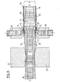
- Fig. 3 shows a vertical arrangement of the casting device.
- Another possibility is to bypass the pistons and allow the pressure medium to act directly on the strip 14 with appropriate sealing.
- springs 15 (FIG. 1) or pistons 16 (FIG. 3) are used, they are provided at a suitable distance a (FIG. 2) and dimensioned such that the mold belt does not deviate from the metallostatic pressure at the outlet of the nozzle Nozzle is lifted off.
- the cooling liquid is high Velocity and acts at an angle ⁇ through the coolant nozzle 19 directly on the mold belt.
- Fig. 4 shows this solution in a vertical orientation.
- the deflection of the mass flow of the cooling liquid by the angle ⁇ results in a force component acting on the mold belt.
- the leakage of the coolant backwards can be kept within permissible limits by means of a labyrinth seal 22, wherein the leakage liquid can be collected in the housing of the device and returned to the coolant system.
- the liquid stream 20 emerging from the coolant nozzle at high speed covers the entire rear surface of the mold belt with a corresponding cooling effect.
- the not shown leadership and support of the same can be done in a known manner.
- FIG. 5 An additional variant according to FIG. 5 is that the static liquid pressure prevailing in the chamber 18 acts on the mold belt and presses it against the casting nozzle.
- the coolant on the belt 13 flows directly from the pressurized chamber 18 through the subsequent coolant nozzle 19. Since the kinetic energy of the liquid flow is exhausted some distance after the nozzle exit, the coolant can be replaced in a known manner at regular intervals.
- the mold strips can also be pressed in that the mold strip is guided in such a way that it runs in a diverging direction in front of the mouth of the pouring nozzle with respect to the center line thereof and is deflected in the pouring nozzle on the pouring nozzle, as a result of the tension of the Mold belt is generated a force acting on the nozzle.
- FIG. 6 illustrates a solution of this type in that both opposing mold belts 13 are directed via guides 22, the distance a of which is smaller than the height h of the pouring nozzle. This results in a diverging direction of the mold belt with respect to the center line CC of the pouring nozzle 11 13. As a result of the tension in the circumferential direction thereof, a force F directed against the pouring nozzle results.
- rollers can also be provided.
- the contact pressure can be adapted to the metallostatic pressure prevailing at the outlet of the nozzle in all of the solutions described above.
- the principle according to the invention of sealing the casting space between the mold belt and the casting nozzle can also be used with other cooling methods.
- cooling can also take place by spraying from nozzles arranged at short intervals or using so-called support heads, for example in accordance with EP-A 0 148 384. Since using the before lying invention between the pouring nozzle and a mold belt creates a certain friction, it is advantageous to apply a wear-resistant layer on the friction point of the nozzle. This can be done by known methods using the flame or plasma spray technique by applying a 0.1 to 0.2 mm thick layer, for example made of aluminum oxide.
- the mouthpiece of the nozzle 11 is provided with inserted wear plates 12.
- Materials such as aluminum oxide, silicon carbide or nitride, metal carbides, etc. are suitable for this.
- One of the measures mentioned can prevent premature wear of the pouring nozzle.
- the Swiss patent no. 508 433 describes a pouring nozzle with inserts made of a self-lubricating material attached near the mouth.
- the inserts serve the purpose of guiding the mouthpiece between the rigid mold halves of a caterpillar mold in such a way that the nozzle surface does not come into contact with the mold, even claiming that the inserts protrude from the surface of the nozzle in order to provide a direct To prevent contact of the nozzle surface with the mold by providing a gap of 0.2 to 0.3 mm between the nozzle and the mold surface.
- a sealing effect can only be achieved with a low metallostatic pressure of at most 20 to 30 mm liquid aluminum column.
- the present invention essentially differs from the type and mode of operation in question, firstly, that the inlays do not protrude from the nozzle surface, secondly, that the inlays are as close as possible to the nozzle outlet, and thirdly, that the inlays consist of a hard, wear-resistant material, in order to increase the operating time of the nozzle under the condition that the mold belts are pressed against it and to increase the to create a free seal between the nozzle and the mold belt for all metallostatic pressures that occur practically in the casting direction, even when casting in an increasing direction.
- two or more of the measures mentioned can be used in combination, which e.g. 1 and 3 already applies in that a certain hydrostatic and hydrodynamic pressure by the coolant is added to the pressure by means of springs or pistons. However, this combined effect can be increased.
- the pressing and sealing device allows, in contrast to the usual known systems, the cooling of the mold belts only after the pressing or sealing point, directly at the mouth of the pouring nozzle 11, i.e. still in the area of the pouring nozzle between the pressing point and the mouth , can take place.
- the cooling starts directly at the mouth of the pouring nozzle 11.
- the orientation of the pouring device or the pouring process is arbitrary. Instead of horizontal or vertical, as shown, it could also be inclined or directed upwards.
- the seal according to the invention has the advantage that it is possible to work with higher metallostatic pressures when the melt supply system is closed, be it that a relatively high pressure results as a result of the vertical arrangement, or that the level in the horizontal or upward pouring direction Tundish is higher than usual.
- the vertical arrangement also offers advantages in terms of symmetrical cooling and generally symmetrical relationships in the casting and solidification process. The higher casting pressure leads to a safe reflow of the melt in the solidification area and thus to a high-quality structure of the cast strip.
Landscapes
- Engineering & Computer Science (AREA)
- Mechanical Engineering (AREA)
- Continuous Casting (AREA)
- Casting Or Compression Moulding Of Plastics Or The Like (AREA)
- Pressure Vessels And Lids Thereof (AREA)
Priority Applications (1)
| Application Number | Priority Date | Filing Date | Title |
|---|---|---|---|
| AT87810106T ATE43264T1 (de) | 1986-03-10 | 1987-02-23 | Abdichtung einer giessduese gegen den giessraum einer stranggiessvorrichtung mit mindestens einem umlaufenden, flexiblen kokillenband. |
Applications Claiming Priority (2)
| Application Number | Priority Date | Filing Date | Title |
|---|---|---|---|
| CH97286 | 1986-03-10 | ||
| CH972/86 | 1986-03-10 |
Publications (2)
| Publication Number | Publication Date |
|---|---|
| EP0237478A1 true EP0237478A1 (fr) | 1987-09-16 |
| EP0237478B1 EP0237478B1 (fr) | 1989-05-24 |
Family
ID=4199483
Family Applications (1)
| Application Number | Title | Priority Date | Filing Date |
|---|---|---|---|
| EP87810106A Expired EP0237478B1 (fr) | 1986-03-10 | 1987-02-23 | Moyen d'étanchéité d'une busette de coulée dans l'espace de coulée d'une machine continue à bande mouvante |
Country Status (8)
| Country | Link |
|---|---|
| US (1) | US4785873A (fr) |
| EP (1) | EP0237478B1 (fr) |
| JP (1) | JP2593470B2 (fr) |
| AT (1) | ATE43264T1 (fr) |
| CA (1) | CA1293848C (fr) |
| DE (1) | DE3760169D1 (fr) |
| ES (1) | ES2008705B3 (fr) |
| GR (2) | GR890300033T1 (fr) |
Cited By (3)
| Publication number | Priority date | Publication date | Assignee | Title |
|---|---|---|---|---|
| EP0278202A2 (fr) * | 1987-02-10 | 1988-08-17 | MANNESMANN Aktiengesellschaft | Installation de coulée continue de billettes fines de métal notamment d'acier |
| DE102010046292A1 (de) | 2009-12-29 | 2011-06-30 | SMS Siemag AG, 40237 | Stranggießanlage und Verfahren zum Stranggießen |
| WO2013000841A1 (fr) | 2011-06-29 | 2013-01-03 | Sms Siemag Ag | Procédé de coulée continue d'une barre de coulée continue et installation de coulée continue |
Families Citing this family (12)
| Publication number | Priority date | Publication date | Assignee | Title |
|---|---|---|---|---|
| CA2128398C (fr) * | 1994-07-19 | 2007-02-06 | John Sulzer | Appareil de coulee en continue de bandes metalliques, injecteur utilise pour ce faire et procede connexe |
| US5725046A (en) * | 1994-09-20 | 1998-03-10 | Aluminum Company Of America | Vertical bar caster |
| US5687789A (en) * | 1995-12-28 | 1997-11-18 | Larex A.G. | Caster with improved coil changing system |
| US5787968A (en) * | 1995-12-28 | 1998-08-04 | Larex A.G. | Movably mounted side dam and an associated method of sealing the side dam against the nozzle of a belt caster |
| US5640868A (en) * | 1995-12-28 | 1997-06-24 | Larex A.G. | Apparatus and method for work hardening an endless belt for use in a belt caster |
| US5613547A (en) * | 1996-01-11 | 1997-03-25 | Larex A.G. | Nozzle with a baffle for a caster and an associated method of casting molten metal |
| US5711367A (en) * | 1996-01-11 | 1998-01-27 | Larex A.G. | Apparatus for delivering molten metal to a caster including wear strips |
| US5671801A (en) * | 1996-01-11 | 1997-09-30 | Larex A.G. | Cooling system for a belt caster and associated methods |
| US5778967A (en) * | 1996-01-11 | 1998-07-14 | Larex A.G. | Side dam for a caster having improved contact with solidifying metal |
| US6173755B1 (en) | 1996-05-23 | 2001-01-16 | Aluminum Company Of America | Nozzle for continuous slab casting |
| US5823246A (en) * | 1997-03-03 | 1998-10-20 | Larex A.G. | Tundish including a baffle for directing molten metal therethrough and an associated caster and method of casting molten metal |
| US5967220A (en) * | 1997-03-25 | 1999-10-19 | Larex, A.G. | Caster including a gas delivery means to resist backflowing and freezing of molten metal to the tip of a nozzle |
Citations (4)
| Publication number | Priority date | Publication date | Assignee | Title |
|---|---|---|---|---|
| FR1418754A (fr) * | 1958-11-19 | 1965-11-26 | Pechiney Prod Chimiques Sa | Améliorations à la technique de la coulée continue |
| CH423109A (de) * | 1964-08-31 | 1966-10-31 | Alusuisse | Giessmaschine zur Herstellung von Bändern |
| DE1758957A1 (de) * | 1968-09-07 | 1971-04-01 | Schloemann Ag | Stranggiesskokille |
| CH508433A (de) * | 1970-06-24 | 1971-06-15 | Prolizenz Ag C O Schweiz Kredi | Düse für die Zuführung des geschmolzenen Metalles beim Bandgiessen in Raupenkokille |
Family Cites Families (11)
| Publication number | Priority date | Publication date | Assignee | Title |
|---|---|---|---|---|
| CH416955A (de) * | 1964-04-20 | 1966-07-15 | Alusuisse | Verfahren und Maschine zum Stranggiessen von Metallen |
| FR1435936A (fr) * | 1965-03-08 | 1966-04-22 | Siderurgie Fse Inst Rech | Procédé et dispositif de coulée continue de produits liquides |
| US3429363A (en) * | 1966-04-14 | 1969-02-25 | Hazelett Strip Casting Corp | Method of cooling the casting belt in a continuous metal casting machine of the drum and belt type |
| US3933193A (en) * | 1971-02-16 | 1976-01-20 | Alcan Research And Development Limited | Apparatus for continuous casting of metal strip between moving belts |
| US3937270A (en) * | 1973-11-09 | 1976-02-10 | Hazelett Strip-Casting Corporation | Twin-belt continuous casting method providing control of the temperature operating conditions at the casting belts |
| JPS582735B2 (ja) * | 1974-07-30 | 1983-01-18 | 古河電気工業株式会社 | レンゾクチユウゾウソウチニオケル チユウユホウホウ |
| DE3029223C2 (de) * | 1980-08-01 | 1984-09-27 | Fried. Krupp Gmbh, 4300 Essen | Einlauf für die Metallschmelze in Stranggießvorrichtungen |
| JPS5820356A (ja) * | 1981-07-29 | 1983-02-05 | Mitsubishi Heavy Ind Ltd | 水平型連続鋳造装置 |
| DE3231321C2 (de) * | 1982-08-23 | 1984-06-07 | Fried. Krupp Gmbh, 4300 Essen | Abdichtung zwischen einer Gießdüse und einer diese umschließenden Stranggießkokille für Stahl mit einem rechteckförmigen Gießquerschnitt |
| JPS59153552A (ja) * | 1983-02-22 | 1984-09-01 | Nippon Kokan Kk <Nkk> | 薄肉鋳片の水平連続鋳造装置 |
| DE3345982C2 (de) * | 1983-12-20 | 1985-11-14 | Fried. Krupp Gmbh, 4300 Essen | Einlauf für die Metallschmelze in Stranggießvorrichtungen, die eine feststehende feuerfeste Gießdüse und eine Kokille mit nur in Gießrichtung bewegten Kokillenwänden aufweisen |
-
1987
- 1987-02-23 EP EP87810106A patent/EP0237478B1/fr not_active Expired
- 1987-02-23 DE DE8787810106T patent/DE3760169D1/de not_active Expired
- 1987-02-23 AT AT87810106T patent/ATE43264T1/de not_active IP Right Cessation
- 1987-02-23 ES ES87810106T patent/ES2008705B3/es not_active Expired
- 1987-02-25 CA CA000530521A patent/CA1293848C/fr not_active Expired - Lifetime
- 1987-02-26 US US07/019,204 patent/US4785873A/en not_active Expired - Lifetime
- 1987-03-09 JP JP62053914A patent/JP2593470B2/ja not_active Expired - Fee Related
-
1989
- 1989-04-12 GR GR89300033T patent/GR890300033T1/el unknown
- 1989-08-23 GR GR89400154T patent/GR3000131T3/el unknown
Patent Citations (4)
| Publication number | Priority date | Publication date | Assignee | Title |
|---|---|---|---|---|
| FR1418754A (fr) * | 1958-11-19 | 1965-11-26 | Pechiney Prod Chimiques Sa | Améliorations à la technique de la coulée continue |
| CH423109A (de) * | 1964-08-31 | 1966-10-31 | Alusuisse | Giessmaschine zur Herstellung von Bändern |
| DE1758957A1 (de) * | 1968-09-07 | 1971-04-01 | Schloemann Ag | Stranggiesskokille |
| CH508433A (de) * | 1970-06-24 | 1971-06-15 | Prolizenz Ag C O Schweiz Kredi | Düse für die Zuführung des geschmolzenen Metalles beim Bandgiessen in Raupenkokille |
Cited By (6)
| Publication number | Priority date | Publication date | Assignee | Title |
|---|---|---|---|---|
| EP0278202A2 (fr) * | 1987-02-10 | 1988-08-17 | MANNESMANN Aktiengesellschaft | Installation de coulée continue de billettes fines de métal notamment d'acier |
| EP0278202A3 (en) * | 1987-02-10 | 1988-12-28 | Mannesmann Aktiengesellschaft | Installation for continuous casting of fine metal strands, especially steel |
| DE102010046292A1 (de) | 2009-12-29 | 2011-06-30 | SMS Siemag AG, 40237 | Stranggießanlage und Verfahren zum Stranggießen |
| WO2011080065A1 (fr) | 2009-12-29 | 2011-07-07 | Sms Siemag Ag | Installation de coulée continue et procédé de coulée continue |
| WO2013000841A1 (fr) | 2011-06-29 | 2013-01-03 | Sms Siemag Ag | Procédé de coulée continue d'une barre de coulée continue et installation de coulée continue |
| DE102011078370A1 (de) | 2011-06-29 | 2013-01-03 | Sms Siemag Ag | Verfahren zum Stranggießen eines Gießstrangs und Stranggießanlage |
Also Published As
| Publication number | Publication date |
|---|---|
| JP2593470B2 (ja) | 1997-03-26 |
| DE3760169D1 (en) | 1989-06-29 |
| ES2008705B3 (es) | 1989-08-01 |
| US4785873A (en) | 1988-11-22 |
| JPS62214854A (ja) | 1987-09-21 |
| GR890300033T1 (en) | 1989-04-12 |
| CA1293848C (fr) | 1992-01-07 |
| ATE43264T1 (de) | 1989-06-15 |
| GR3000131T3 (en) | 1990-11-29 |
| EP0237478B1 (fr) | 1989-05-24 |
Similar Documents
| Publication | Publication Date | Title |
|---|---|---|
| EP0237478B1 (fr) | Moyen d'étanchéité d'une busette de coulée dans l'espace de coulée d'une machine continue à bande mouvante | |
| DE3719976C2 (fr) | ||
| EP1957220B1 (fr) | Procede de fonctionnement d'une machine de coulee a deux cylindres pour la coulee de metaux en fusion en bande coulee | |
| CH624322A5 (en) | Device for cooling and guiding a revolving mould belt in a continuous casting installation | |
| DE10042078A1 (de) | Verfahren und Vorrichtung zum kontinuierlichen Gießen von Stahlband aus Stahlschmelze | |
| DE2709540A1 (de) | Verfahren zum kuehlen und fuehren eines umlaufenden kokillenbandes an einer vorrichtung zum kontinuierlichen giessen von straengen | |
| EP0233147B1 (fr) | Procédé et dispositif de coulée continue entre rouleaux | |
| DE102011078370A1 (de) | Verfahren zum Stranggießen eines Gießstrangs und Stranggießanlage | |
| DE3207010A1 (de) | Metallblech-durchlaufgiesseinrichtung | |
| WO2021001495A1 (fr) | Acheminement de matière fondue pour installations de coulée en bande | |
| DE2758514C3 (de) | Stahlstranggießkokille für Knüppel- und Vorblockstränge | |
| DE102008010688B4 (de) | Verfahren und Zwei-Walzen-Gießmaschine zum Herstellen von aus einer Metallschmelze gegossenem Band | |
| DE2551803A1 (de) | Verfahren und vorrichtung zum kontinuierlichen giessen eines metallischen stranges | |
| DE3402751C2 (fr) | ||
| EP1827735B1 (fr) | Procede et dispositif de coulee en bande de metaux | |
| DE2731748B2 (de) | Rollenführungsgerüst für eine Stahlstranggießanlage | |
| EP1646464B1 (fr) | Procede d'exploitation d'une machine de coulee en bande pour produire un feuillard | |
| DD201650A5 (de) | Metalleinlauf in stranggiessvorrichtungen mit bewegten kokillenwaenden | |
| DE102008031476A1 (de) | Gießvorrichtung | |
| CH640758A5 (de) | Stranggiessvorrichtung. | |
| DE19960593C2 (de) | Vorrichtung zum Kühlen eines metallischen Gussstrangs | |
| DE865940C (de) | Maschine zum Giessen von Metallbaendern u. dgl. | |
| DE2226095C3 (de) | Verfahren und Vorrichtung zum Fördern eines Stranges durch die Strangführung einer Stahlstranggießanlage | |
| DE3337583C1 (de) | Vorrichtung zum Bandgiessen von Stahl in einer Stranggiesskokille mit mitlaufenden Kokillenwaenden | |
| EP0197135B1 (fr) | Dispositif de coulee des barres |
Legal Events
| Date | Code | Title | Description |
|---|---|---|---|
| PUAI | Public reference made under article 153(3) epc to a published international application that has entered the european phase |
Free format text: ORIGINAL CODE: 0009012 |
|
| AK | Designated contracting states |
Kind code of ref document: A1 Designated state(s): AT BE CH DE ES FR GB GR IT LI LU NL SE |
|
| 17P | Request for examination filed |
Effective date: 19871002 |
|
| 17Q | First examination report despatched |
Effective date: 19880428 |
|
| GRAA | (expected) grant |
Free format text: ORIGINAL CODE: 0009210 |
|
| AK | Designated contracting states |
Kind code of ref document: B1 Designated state(s): AT BE CH DE ES FR GB GR IT LI LU NL SE |
|
| REF | Corresponds to: |
Ref document number: 43264 Country of ref document: AT Date of ref document: 19890615 Kind code of ref document: T |
|
| ITF | It: translation for a ep patent filed |
Owner name: BARZANO' E ZANARDO MILANO S.P.A. |
|
| REF | Corresponds to: |
Ref document number: 3760169 Country of ref document: DE Date of ref document: 19890629 |
|
| GBT | Gb: translation of ep patent filed (gb section 77(6)(a)/1977) | ||
| ET | Fr: translation filed | ||
| PLBE | No opposition filed within time limit |
Free format text: ORIGINAL CODE: 0009261 |
|
| STAA | Information on the status of an ep patent application or granted ep patent |
Free format text: STATUS: NO OPPOSITION FILED WITHIN TIME LIMIT |
|
| 26N | No opposition filed | ||
| REG | Reference to a national code |
Ref country code: GR Ref legal event code: FG4A Free format text: 3000131 |
|
| ITTA | It: last paid annual fee | ||
| EPTA | Lu: last paid annual fee | ||
| EAL | Se: european patent in force in sweden |
Ref document number: 87810106.2 |
|
| PGFP | Annual fee paid to national office [announced via postgrant information from national office to epo] |
Ref country code: NL Payment date: 20011214 Year of fee payment: 16 |
|
| PGFP | Annual fee paid to national office [announced via postgrant information from national office to epo] |
Ref country code: LU Payment date: 20011221 Year of fee payment: 16 |
|
| REG | Reference to a national code |
Ref country code: GB Ref legal event code: IF02 |
|
| PGFP | Annual fee paid to national office [announced via postgrant information from national office to epo] |
Ref country code: AT Payment date: 20020107 Year of fee payment: 16 |
|
| PGFP | Annual fee paid to national office [announced via postgrant information from national office to epo] |
Ref country code: GB Payment date: 20020108 Year of fee payment: 16 |
|
| PGFP | Annual fee paid to national office [announced via postgrant information from national office to epo] |
Ref country code: GR Payment date: 20020124 Year of fee payment: 16 |
|
| PGFP | Annual fee paid to national office [announced via postgrant information from national office to epo] |
Ref country code: FR Payment date: 20020131 Year of fee payment: 16 |
|
| PGFP | Annual fee paid to national office [announced via postgrant information from national office to epo] |
Ref country code: SE Payment date: 20020201 Year of fee payment: 16 |
|
| PGFP | Annual fee paid to national office [announced via postgrant information from national office to epo] |
Ref country code: ES Payment date: 20020212 Year of fee payment: 16 |
|
| PGFP | Annual fee paid to national office [announced via postgrant information from national office to epo] |
Ref country code: DE Payment date: 20020228 Year of fee payment: 16 |
|
| PGFP | Annual fee paid to national office [announced via postgrant information from national office to epo] |
Ref country code: BE Payment date: 20020318 Year of fee payment: 16 |
|
| PGFP | Annual fee paid to national office [announced via postgrant information from national office to epo] |
Ref country code: CH Payment date: 20020325 Year of fee payment: 16 |
|
| PG25 | Lapsed in a contracting state [announced via postgrant information from national office to epo] |
Ref country code: LU Free format text: LAPSE BECAUSE OF NON-PAYMENT OF DUE FEES Effective date: 20030223 Ref country code: GB Free format text: LAPSE BECAUSE OF NON-PAYMENT OF DUE FEES Effective date: 20030223 Ref country code: AT Free format text: LAPSE BECAUSE OF NON-PAYMENT OF DUE FEES Effective date: 20030223 |
|
| PG25 | Lapsed in a contracting state [announced via postgrant information from national office to epo] |
Ref country code: SE Free format text: LAPSE BECAUSE OF NON-PAYMENT OF DUE FEES Effective date: 20030224 Ref country code: ES Free format text: LAPSE BECAUSE OF NON-PAYMENT OF DUE FEES Effective date: 20030224 |
|
| PG25 | Lapsed in a contracting state [announced via postgrant information from national office to epo] |
Ref country code: LI Free format text: LAPSE BECAUSE OF NON-PAYMENT OF DUE FEES Effective date: 20030228 Ref country code: CH Free format text: LAPSE BECAUSE OF NON-PAYMENT OF DUE FEES Effective date: 20030228 Ref country code: BE Free format text: LAPSE BECAUSE OF NON-PAYMENT OF DUE FEES Effective date: 20030228 |
|
| PG25 | Lapsed in a contracting state [announced via postgrant information from national office to epo] |
Ref country code: NL Free format text: LAPSE BECAUSE OF NON-PAYMENT OF DUE FEES Effective date: 20030901 |
|
| PG25 | Lapsed in a contracting state [announced via postgrant information from national office to epo] |
Ref country code: DE Free format text: LAPSE BECAUSE OF NON-PAYMENT OF DUE FEES Effective date: 20030902 |
|
| PG25 | Lapsed in a contracting state [announced via postgrant information from national office to epo] |
Ref country code: GR Free format text: LAPSE BECAUSE OF NON-PAYMENT OF DUE FEES Effective date: 20030904 |
|
| EUG | Se: european patent has lapsed | ||
| GBPC | Gb: european patent ceased through non-payment of renewal fee | ||
| REG | Reference to a national code |
Ref country code: CH Ref legal event code: PL |
|
| PG25 | Lapsed in a contracting state [announced via postgrant information from national office to epo] |
Ref country code: FR Free format text: LAPSE BECAUSE OF NON-PAYMENT OF DUE FEES Effective date: 20031031 |
|
| NLV4 | Nl: lapsed or anulled due to non-payment of the annual fee |
Effective date: 20030901 |
|
| REG | Reference to a national code |
Ref country code: FR Ref legal event code: ST |
|
| REG | Reference to a national code |
Ref country code: ES Ref legal event code: FD2A Effective date: 20030224 |
|
| PG25 | Lapsed in a contracting state [announced via postgrant information from national office to epo] |
Ref country code: IT Free format text: LAPSE BECAUSE OF NON-PAYMENT OF DUE FEES;WARNING: LAPSES OF ITALIAN PATENTS WITH EFFECTIVE DATE BEFORE 2007 MAY HAVE OCCURRED AT ANY TIME BEFORE 2007. THE CORRECT EFFECTIVE DATE MAY BE DIFFERENT FROM THE ONE RECORDED. Effective date: 20050223 |