EP0234482B1 - Gerät, insbesondere Videorecorder - Google Patents
Gerät, insbesondere Videorecorder Download PDFInfo
- Publication number
- EP0234482B1 EP0234482B1 EP87102225A EP87102225A EP0234482B1 EP 0234482 B1 EP0234482 B1 EP 0234482B1 EP 87102225 A EP87102225 A EP 87102225A EP 87102225 A EP87102225 A EP 87102225A EP 0234482 B1 EP0234482 B1 EP 0234482B1
- Authority
- EP
- European Patent Office
- Prior art keywords
- conductors
- head
- pickup
- head wheel
- magnetic
- Prior art date
- Legal status (The legal status is an assumption and is not a legal conclusion. Google has not performed a legal analysis and makes no representation as to the accuracy of the status listed.)
- Expired - Lifetime
Links
- 239000004020 conductor Substances 0.000 claims description 57
- 230000005684 electric field Effects 0.000 abstract description 5
- 230000001360 synchronised effect Effects 0.000 description 6
- 230000005540 biological transmission Effects 0.000 description 2
- 238000000926 separation method Methods 0.000 description 2
- 230000001154 acute effect Effects 0.000 description 1
- 230000015572 biosynthetic process Effects 0.000 description 1
- 230000001419 dependent effect Effects 0.000 description 1
- 238000011161 development Methods 0.000 description 1
- 230000018109 developmental process Effects 0.000 description 1
- 239000002184 metal Substances 0.000 description 1
- 238000000034 method Methods 0.000 description 1
Images

Classifications
-
- G—PHYSICS
- G11—INFORMATION STORAGE
- G11B—INFORMATION STORAGE BASED ON RELATIVE MOVEMENT BETWEEN RECORD CARRIER AND TRANSDUCER
- G11B15/00—Driving, starting or stopping record carriers of filamentary or web form; Driving both such record carriers and heads; Guiding such record carriers or containers therefor; Control thereof; Control of operating function
- G11B15/18—Driving; Starting; Stopping; Arrangements for control or regulation thereof
- G11B15/46—Controlling, regulating, or indicating speed
- G11B15/467—Controlling, regulating, or indicating speed in arrangements for recording or reproducing wherein both record carriers and heads are driven
- G11B15/473—Controlling, regulating, or indicating speed in arrangements for recording or reproducing wherein both record carriers and heads are driven by controlling the speed of the heads
-
- G—PHYSICS
- G11—INFORMATION STORAGE
- G11B—INFORMATION STORAGE BASED ON RELATIVE MOVEMENT BETWEEN RECORD CARRIER AND TRANSDUCER
- G11B15/00—Driving, starting or stopping record carriers of filamentary or web form; Driving both such record carriers and heads; Guiding such record carriers or containers therefor; Control thereof; Control of operating function
- G11B15/18—Driving; Starting; Stopping; Arrangements for control or regulation thereof
- G11B15/1808—Driving of both record carrier and head
-
- G—PHYSICS
- G11—INFORMATION STORAGE
- G11B—INFORMATION STORAGE BASED ON RELATIVE MOVEMENT BETWEEN RECORD CARRIER AND TRANSDUCER
- G11B15/00—Driving, starting or stopping record carriers of filamentary or web form; Driving both such record carriers and heads; Guiding such record carriers or containers therefor; Control thereof; Control of operating function
- G11B15/18—Driving; Starting; Stopping; Arrangements for control or regulation thereof
- G11B15/46—Controlling, regulating, or indicating speed
- G11B15/467—Controlling, regulating, or indicating speed in arrangements for recording or reproducing wherein both record carriers and heads are driven
- G11B15/473—Controlling, regulating, or indicating speed in arrangements for recording or reproducing wherein both record carriers and heads are driven by controlling the speed of the heads
- G11B15/4731—Controlling, regulating, or indicating speed in arrangements for recording or reproducing wherein both record carriers and heads are driven by controlling the speed of the heads control of headwheel rotation
-
- G—PHYSICS
- G11—INFORMATION STORAGE
- G11B—INFORMATION STORAGE BASED ON RELATIVE MOVEMENT BETWEEN RECORD CARRIER AND TRANSDUCER
- G11B5/00—Recording by magnetisation or demagnetisation of a record carrier; Reproducing by magnetic means; Record carriers therefor
- G11B5/48—Disposition or mounting of heads or head supports relative to record carriers ; arrangements of heads, e.g. for scanning the record carrier to increase the relative speed
- G11B5/52—Disposition or mounting of heads or head supports relative to record carriers ; arrangements of heads, e.g. for scanning the record carrier to increase the relative speed with simultaneous movement of head and record carrier, e.g. rotation of head
- G11B5/53—Disposition or mounting of heads on rotating support
Definitions
- the invention relates to a device, in particular a video recorder, according to the preamble of patent claim 1.
- a method for determining the angular position of the magnetic heads relative to the tape.
- a head wheel disc contains two rotating permanent magnets which, during rotation in a stationary head or in a stationary coil outside the head, permanently installed in a head wheel environment, generate pulses of alternating polarity.
- the impulses serve as a criterion for the respective position and speed of the top wheel disc (page 6, first paragraph).
- the invention has for its object to provide an arrangement that improves the display of the angular position of the head wheel disc.
- the object is achieved by the features specified in patent claims 1. Distributive developments of the invention are specified in dependent claims.
- a head wheel arrangement is also known (US-A-4 025 934), in which the head wheel is assigned a transmitter for high frequencies with two conductors lying next to one another.
- a rotating Archimedean spiral made of metal serves as an indicator and is arranged between the transmitter and the sensor in the function of a receiving coil.
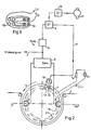
- head wheel 1 shows a head wheel disk or a head drum 1, hereinafter referred to as head wheel, with two magnetic heads 2 and 3.
- a magnetic tape 4 is placed around the head wheel 1.
- the head wheel 1 rotates in the direction of 5.
- Fields in the magnetic tape 4 induce voltages in the magnetic heads 2 and 3, which are given to a demodulator 6 via lines.
- the demodulator 6 demodulates the signals coming from the magnetic tape 4 and supplies demodulated signals to the output 7.
- a video signal can be tapped at output 7.
- a synchronous separation stage 8 synchronization words, hereinafter called synchronous words, are filtered out. These synchronous words are forwarded to a controller 9.
- the controller 9 controls a head wheel control 11 via an amplifier 10.
- Two conductors 12 and 13 are arranged parallel to the axis of rotation of the head wheel 1.
- the conductors 12 and 13 are permanently installed in the chassis of the video recorder, hereinafter referred to as the head wheel environment.
- An AC voltage source 15 supplies the conductors 12 and 13 with an alternating current I1 via a limiting resistor 14.
- the conductors 12 and 13 are elongated.
- the arrow direction 25 indicates the current direction.
- the current I1 flows through the conductor 12 in the direction of the drawing plane and the conductor 13 in the direction out of the drawing plane.
- the current I1 flows through the two conductors 12, 13 in the opposite direction, that is to say in the opposite direction, so that an electrical field is formed around the conductors 12, 13 with a minimal field strength between the two conductors.
- a head position circuit 16 separates pulses from the signals coming from the magnetic heads 2 and 3. These pulses are induced by conductors 12 and 13. The pulses are passed on from the head position circuit 16 to the controller 9 via the line 17.
- the controller 9 compares the synchronous words coming from the synchronous separation 8 with the head position pulses and regulates the head wheel control 11 on the basis of the synchronous words and the pulses.
- FIG. 2 shows the two elongated conductors 12 and 13 fixedly installed in the head wheel 1 parallel to the axis of rotation of the head wheel 1.
- the conductors 12 and 13 are supplied by the AC voltage source 15 and supplied with a current I2 via a limiting resistor 14.
- the two conductors 12 and 13 are connected to the voltage source and the limiting resistor 14 via slip rings 19 and 20 and via contact wipers.
- the magnetic heads 2 and 3 and the conductors 12 and 13 are advantageously arranged on the head wheel in two different planes, so that the conductors 12 and 13 do not influence the magnetic tape 4.
- the conductors 12 and 13 induce a voltage in the magnetic head 18.
- the voltage is passed on to the controller 9 via the line 17.
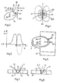
- FIG. 3 shows a magnetic head 2 on a head wheel track 21.
- the magnetic head 2 rotates on the head wheel track 21 and is displaceable in the direction of the axis of rotation 25.
- Two conductor loops 22 and 23 are arranged on the top wheel track 21.
- Each of the two conductor loops 22, 23 consists of two conductors 12 and 13 through which current flows.
- the conductor loop 23 is arranged parallel to the axis of rotation 25.
- the conductor loop 22 extends over a stroke region of the top wheel track 21.
- the conductor loop 22 forms an acute angle or a V-shaped arrangement with the conductor loop 23.
- the conductor loop 22 is arranged in such a way that it can induce a voltage in the magnetic head 2 over the entire stroke range of the knock wheel track 21.
- An exact determination of the head position 2 is possible via the conductor loop 23.
- a speed of the magnetic head 2 can be determined via the frequency of the induced pulses. Due to the inclined position of the conductor loop 22 relative to the conductor loop 23, different distances between the conductor loops 22 and 23 are predetermined.
- a height shift of the top wheel track in the direction of the axis of rotation 25 over a stroke range can be calculated from the different distances between the conductor tracks 22, 23.
- the stroke range is used to sequentially scan several parallel longitudinal tracks, which are arranged in blocks on a magnetic tape, over a height, which corresponds to the width of a magnetic tape.
- Fig. 4 shows two atomic conductors 12 and 13, which build up an electric field with the field lines 24.
- the two electrical conductors 12 and 13 are arranged on a top wheel track 21. Doing a mathematical quadrature or amount formation, which corresponds to an electrical rectification, this electrical field is minimal at location X0. See also (equation (4) on page 280 in) G. Joos, textbook of theoretical physics, eighth edition, Leipzig 1954, Akademiscbe publishing company Geest & Portig K.-G.
- FIG. 5 shows an induced voltage U after rectification, which is induced in a magnetic head on the head wheel path 21 at the point X0 in a magnetic head. Viewing with a time abscissa and a time to is also possible. Due to the voltage difference between U1 and U0 in the vicinity of point X0 an exact determination of the phase or the angular position of the heads 2, 3 or the head position on a head wheel track 21 is possible. The electric field has a strong gradient in the vicinity of X0. The induced voltage changes its sign at point X0. For a good transmission, the frequency of the polarity change of the currents I1-I4 with approximately the resonance frequency of a head / transmission system must be selected. That means choosing a frequency at which the system of head, equalizer and amplifier reacts most sensitively.
- Fig. 6 shows the head wheel 1 with the two magnetic heads 2 and 3, which is movably mounted in both directions 26 and 27 in the direction of the axis of rotation 25.
- the two conductor loops 22 and 23 are permanently installed in the head wheel environment 26.
- FIG 7 shows the top wheel environment 26 with the two conductor loops 22 and 23.
- Each conductor loop 22 and 23 has conductors 12 and 13.
- the current loop I1 flows through the conductor loop 22 and the current 12 flows through the conductor loop 23.
- FIG. 8 shows a V-shaped arrangement with a conductor loop 22.
- Each conductor 12 and 13 forms a V-shaped arrangement.
- a conductor loop 22 through which a current I1 flows is necessary for this V-shaped arrangement.
- Fig. 9 shows several conductors 12 and 13 in a coil-shaped arrangement.
- the distance s between the two conductors is of the order of the distance d between each of the conductors 12 and 13 and the heads 2, 3.
- the distances s and d are small compared to the length of the circumference of the top wheel track.
- the distance s between the two conductors is ideally zero.
Landscapes
- Measurement Of Length, Angles, Or The Like Using Electric Or Magnetic Means (AREA)
- Adjustment Of The Magnetic Head Position Track Following On Tapes (AREA)
- Recording Or Reproducing By Magnetic Means (AREA)
- Transmission And Conversion Of Sensor Element Output (AREA)
Priority Applications (1)
| Application Number | Priority Date | Filing Date | Title |
|---|---|---|---|
| AT87102225T ATE68304T1 (de) | 1986-02-26 | 1987-02-17 | Geraet, insbesondere videorecorder. |
Applications Claiming Priority (2)
| Application Number | Priority Date | Filing Date | Title |
|---|---|---|---|
| DE19863606091 DE3606091A1 (de) | 1986-02-26 | 1986-02-26 | Geraet, insbesondere videorecorder |
| DE3606091 | 1986-02-26 |
Publications (2)
| Publication Number | Publication Date |
|---|---|
| EP0234482A1 EP0234482A1 (de) | 1987-09-02 |
| EP0234482B1 true EP0234482B1 (de) | 1991-10-09 |
Family
ID=6294918
Family Applications (1)
| Application Number | Title | Priority Date | Filing Date |
|---|---|---|---|
| EP87102225A Expired - Lifetime EP0234482B1 (de) | 1986-02-26 | 1987-02-17 | Gerät, insbesondere Videorecorder |
Country Status (8)
| Country | Link |
|---|---|
| US (1) | US4930025A (el) |
| EP (1) | EP0234482B1 (el) |
| JP (1) | JPS62204460A (el) |
| KR (1) | KR870008300A (el) |
| AT (1) | ATE68304T1 (el) |
| DE (2) | DE3606091A1 (el) |
| ES (1) | ES2026140T3 (el) |
| GR (1) | GR3003532T3 (el) |
Families Citing this family (5)
| Publication number | Priority date | Publication date | Assignee | Title |
|---|---|---|---|---|
| DE3829182A1 (de) * | 1988-08-29 | 1990-03-08 | Broadcast Television Syst | Magnetbandgeraet zur aufzeichnung und wiedergabe von datensignalen |
| KR930005877B1 (ko) * | 1988-11-30 | 1993-06-25 | 주식회사 금성사 | 칼라 디스플레이 튜브용 전자총 |
| US5745316A (en) * | 1991-09-20 | 1998-04-28 | Deutsche Thomson Brandt Gmbh | Phase detector for a recorder/player using a conducting loop driven by a winding strand of the head drum motor |
| DE4131278A1 (de) * | 1991-09-20 | 1993-03-25 | Thomson Brandt Gmbh | Recorder mit antriebs-phasendetektor |
| CN1068449C (zh) * | 1996-01-17 | 2001-07-11 | 三星电子株式会社 | 磁带记录设备的磁头位置检测装置 |
Family Cites Families (14)
| Publication number | Priority date | Publication date | Assignee | Title |
|---|---|---|---|---|
| GB931752A (en) * | 1960-08-15 | 1963-07-17 | Bush And Rank Cintel Ltd | Improvements in rotary-head magnetic recording and reproducing equipment |
| BE668533A (el) * | 1964-08-19 | |||
| AT278177B (de) * | 1968-04-01 | 1970-01-26 | Philips Nv | Vorrichtung zur Gewinnung einer Impulsfolge |
| DE1774502C3 (de) * | 1968-07-03 | 1974-02-14 | Siemens Ag, 1000 Berlin U. 8000 Muenchen | Anordnung zur Spurauswahlsteuerung der Schreib-Leseköpfe bei einem Magnetplattenspeicher |
| DE1952369B2 (de) * | 1969-10-17 | 1971-10-21 | Blaupunkt-Werke Gmbh, 3200 Hildesheim | Anordnung zur justierung von videokoepfen auf einem kopftraeger |
| DE2137918A1 (de) * | 1971-07-23 | 1973-02-08 | Siemens Ag | Schleifringlos gleichstromerregte elektrische maschine, insbesondere blindleistungsmaschine |
| JPS5151215Y2 (el) * | 1972-10-20 | 1976-12-08 | ||
| AT322642B (de) * | 1973-08-01 | 1975-05-26 | Philips Nv | Aufzeichnungs- und wiedergabegerät |
| DE2521163C2 (de) * | 1975-05-13 | 1977-06-16 | Frieseke & Hoepfner Gmbh | Einrichtung zur ermittlung einer der drehzahl oder dem drehwinkel einer achse entsprechenden groesse |
| JPS51138410A (en) * | 1975-05-26 | 1976-11-30 | Sony Corp | Method of recording and reproducing signal |
| DE2751180C2 (de) * | 1977-11-16 | 1979-11-15 | Grundig E.M.V. Elektro-Mechanische Versuchsanstalt Max Grundig, 8510 Fuerth | Verfahren und Anordnung zur störungsfreien Standbildwiedergabe |
| DE2901676A1 (de) * | 1979-01-17 | 1980-08-14 | Papst Motoren Kg | Kollektorloser gleichstrommotor |
| DE3115670A1 (de) * | 1981-04-18 | 1982-11-04 | Licentia Patent-Verwaltungs-Gmbh, 6000 Frankfurt | Videorecorder mit schraegspuraufzeichnung |
| JPS6035317U (ja) * | 1983-08-18 | 1985-03-11 | アルプス電気株式会社 | 磁気ヘツド |
-
1986
- 1986-02-26 DE DE19863606091 patent/DE3606091A1/de not_active Withdrawn
-
1987
- 1987-02-13 JP JP62029951A patent/JPS62204460A/ja active Pending
- 1987-02-17 DE DE8787102225T patent/DE3773504D1/de not_active Expired - Fee Related
- 1987-02-17 ES ES198787102225T patent/ES2026140T3/es not_active Expired - Lifetime
- 1987-02-17 EP EP87102225A patent/EP0234482B1/de not_active Expired - Lifetime
- 1987-02-17 AT AT87102225T patent/ATE68304T1/de not_active IP Right Cessation
- 1987-02-26 KR KR870001652A patent/KR870008300A/ko not_active Application Discontinuation
-
1989
- 1989-01-17 US US07/298,203 patent/US4930025A/en not_active Expired - Fee Related
-
1992
- 1992-01-08 GR GR920400005T patent/GR3003532T3/el unknown
Also Published As
| Publication number | Publication date |
|---|---|
| US4930025A (en) | 1990-05-29 |
| JPS62204460A (ja) | 1987-09-09 |
| DE3606091A1 (de) | 1987-08-27 |
| ATE68304T1 (de) | 1991-10-15 |
| KR870008300A (ko) | 1987-09-25 |
| GR3003532T3 (el) | 1993-03-16 |
| ES2026140T3 (es) | 1992-04-16 |
| DE3773504D1 (de) | 1991-11-14 |
| EP0234482A1 (de) | 1987-09-02 |
Similar Documents
| Publication | Publication Date | Title |
|---|---|---|
| DE2907797C2 (el) | ||
| DE4437289C2 (de) | Magnetaufzeichnungsdiskette, zugehöriges Diskettenantriebs-Spurverfolgungssystem, und zugehöriges Verfahren | |
| DE2011222C3 (de) | Anordnung zur Bestimmung von Koordinaten auf einer Fläche | |
| DE2752027A1 (de) | Anordnung zum spurfuehren eines gleisfreien fahrzeuges | |
| DE112008001432T5 (de) | Linearmotor-Positionserfassungssystem | |
| DE102012204917A1 (de) | Positionserfassungsvorrichtung und Verfahren zum Erfassen einer Position eines beweglichen Elements einer Antriebsvorrichtung | |
| DE112007001939T5 (de) | Verfahren zum Verarbeiten von Kodierersignalen | |
| DE3308352A1 (de) | Magnetdetektorvorrichtung | |
| DE4344494C2 (de) | Verfahren und Vorrichtung zur Vermessung einer Achsdrehbewegung | |
| DE2350990A1 (de) | Verfaaren und vorrichtung zur phasenempfindlichen muenzpruefung | |
| DE3112886A1 (de) | Verfahren zum erkennen einer kante eines magnetischen mediums und vorrichtung zur druchfuehrung des verfahrens | |
| DE3808198A1 (de) | Vorrichtung zum aufzeichnen/wiedergeben eines digitalsignals | |
| DE3303961A1 (de) | Vorrichtung zur inkrementalen erfassung der fahrzeuglage eines magnetschwebefahrzeuges | |
| EP0234482B1 (de) | Gerät, insbesondere Videorecorder | |
| DE3231558C2 (el) | ||
| DE3240478C2 (el) | ||
| DE2454522A1 (de) | Magnetoresistives element | |
| DE3040316C2 (de) | Verfahren und Vorrichtung zur kontaktlosen Messung von Gleich- und Wechselströmen, insbesondere von Strom-Augenblickswerten | |
| DE3418526A1 (de) | Verfahren und anordnung zur fehlersignalermittlung in einem magnetplattenspeicher und testmagnetplatte dafuer | |
| DE3836508A1 (de) | Vorrichtung zum erfassen der geschwindigkeit eines sich bewegenden koerpers | |
| DE19504307A1 (de) | Einrichtung zur Erfassung von Position und/oder Geschwindigkeit eines beweglichen Geräteteils | |
| DE2929964C2 (de) | Verfahren zur Kompensation von magnetischen Störfeldern von Objekten mittels magnetischer Eigenschutzanlagen | |
| EP0204956B1 (de) | Gerät, insbesondere Videorecorder | |
| DE4001533C2 (el) | ||
| DE3323984A1 (de) | Mit einem laengs einer fahrspur sich erstreckenden schlitzhohlleiter koppelbare antenne eines fahrzeugs |
Legal Events
| Date | Code | Title | Description |
|---|---|---|---|
| PUAI | Public reference made under article 153(3) epc to a published international application that has entered the european phase |
Free format text: ORIGINAL CODE: 0009012 |
|
| AK | Designated contracting states |
Kind code of ref document: A1 Designated state(s): AT BE CH DE ES FR GB GR IT LI LU NL SE |
|
| 17P | Request for examination filed |
Effective date: 19880205 |
|
| 17Q | First examination report despatched |
Effective date: 19900511 |
|
| GRAA | (expected) grant |
Free format text: ORIGINAL CODE: 0009210 |
|
| AK | Designated contracting states |
Kind code of ref document: B1 Designated state(s): AT BE CH DE ES FR GB GR IT LI LU NL SE |
|
| REF | Corresponds to: |
Ref document number: 68304 Country of ref document: AT Date of ref document: 19911015 Kind code of ref document: T |
|
| ITF | It: translation for a ep patent filed |
Owner name: BARZANO' E ZANARDO MILANO S.P.A. |
|
| REF | Corresponds to: |
Ref document number: 3773504 Country of ref document: DE Date of ref document: 19911114 |
|
| ET | Fr: translation filed | ||
| GBT | Gb: translation of ep patent filed (gb section 77(6)(a)/1977) | ||
| PGFP | Annual fee paid to national office [announced via postgrant information from national office to epo] |
Ref country code: LU Payment date: 19920130 Year of fee payment: 6 |
|
| PGFP | Annual fee paid to national office [announced via postgrant information from national office to epo] |
Ref country code: SE Payment date: 19920205 Year of fee payment: 6 |
|
| PGFP | Annual fee paid to national office [announced via postgrant information from national office to epo] |
Ref country code: GB Payment date: 19920211 Year of fee payment: 6 |
|
| PG25 | Lapsed in a contracting state [announced via postgrant information from national office to epo] |
Ref country code: ES Free format text: LAPSE BECAUSE OF EXPIRATION OF PROTECTION Effective date: 19920218 |
|
| PGFP | Annual fee paid to national office [announced via postgrant information from national office to epo] |
Ref country code: BE Payment date: 19920219 Year of fee payment: 6 |
|
| PGFP | Annual fee paid to national office [announced via postgrant information from national office to epo] |
Ref country code: GR Payment date: 19920225 Year of fee payment: 6 |
|
| PGFP | Annual fee paid to national office [announced via postgrant information from national office to epo] |
Ref country code: CH Payment date: 19920228 Year of fee payment: 6 |
|
| PGFP | Annual fee paid to national office [announced via postgrant information from national office to epo] |
Ref country code: NL Payment date: 19920229 Year of fee payment: 6 |
|
| REG | Reference to a national code |
Ref country code: ES Ref legal event code: FG2A Ref document number: 2026140 Country of ref document: ES Kind code of ref document: T3 |
|
| EPTA | Lu: last paid annual fee | ||
| PLBE | No opposition filed within time limit |
Free format text: ORIGINAL CODE: 0009261 |
|
| STAA | Information on the status of an ep patent application or granted ep patent |
Free format text: STATUS: NO OPPOSITION FILED WITHIN TIME LIMIT |
|
| 26N | No opposition filed | ||
| PG25 | Lapsed in a contracting state [announced via postgrant information from national office to epo] |
Ref country code: FR Effective date: 19921030 |
|
| PG25 | Lapsed in a contracting state [announced via postgrant information from national office to epo] |
Ref country code: DE Effective date: 19921103 |
|
| REG | Reference to a national code |
Ref country code: GR Ref legal event code: FG4A Free format text: 3003532 |
|
| REG | Reference to a national code |
Ref country code: FR Ref legal event code: ST |
|
| PGFP | Annual fee paid to national office [announced via postgrant information from national office to epo] |
Ref country code: AT Payment date: 19930210 Year of fee payment: 7 |
|
| PG25 | Lapsed in a contracting state [announced via postgrant information from national office to epo] |
Ref country code: LU Free format text: LAPSE BECAUSE OF NON-PAYMENT OF DUE FEES Effective date: 19930217 Ref country code: GB Effective date: 19930217 |
|
| PG25 | Lapsed in a contracting state [announced via postgrant information from national office to epo] |
Ref country code: SE Effective date: 19930218 |
|
| PG25 | Lapsed in a contracting state [announced via postgrant information from national office to epo] |
Ref country code: LI Effective date: 19930228 Ref country code: CH Effective date: 19930228 Ref country code: BE Effective date: 19930228 |
|
| BERE | Be: lapsed |
Owner name: DEUTSCHE THOMSON-BRANDT G.M.B.H. Effective date: 19930228 |
|
| PG25 | Lapsed in a contracting state [announced via postgrant information from national office to epo] |
Ref country code: GR Free format text: THE PATENT HAS BEEN ANNULLED BY A DECISION OF A NATIONAL AUTHORITY Effective date: 19930831 |
|
| PG25 | Lapsed in a contracting state [announced via postgrant information from national office to epo] |
Ref country code: NL Effective date: 19930901 |
|
| GBPC | Gb: european patent ceased through non-payment of renewal fee |
Effective date: 19930217 |
|
| NLV4 | Nl: lapsed or anulled due to non-payment of the annual fee | ||
| REG | Reference to a national code |
Ref country code: CH Ref legal event code: PL |
|
| PG25 | Lapsed in a contracting state [announced via postgrant information from national office to epo] |
Ref country code: AT Effective date: 19940217 |
|
| REG | Reference to a national code |
Ref country code: GR Ref legal event code: MM2A Free format text: 3003532 |
|
| EUG | Se: european patent has lapsed |
Ref document number: 87102225.7 Effective date: 19930912 |
|
| REG | Reference to a national code |
Ref country code: ES Ref legal event code: FD2A Effective date: 19991201 |
|
| PG25 | Lapsed in a contracting state [announced via postgrant information from national office to epo] |
Ref country code: IT Free format text: LAPSE BECAUSE OF NON-PAYMENT OF DUE FEES Effective date: 20050217 |