EP0234482B1 - Apparatus, particularly video tape recorder - Google Patents
Apparatus, particularly video tape recorder Download PDFInfo
- Publication number
- EP0234482B1 EP0234482B1 EP87102225A EP87102225A EP0234482B1 EP 0234482 B1 EP0234482 B1 EP 0234482B1 EP 87102225 A EP87102225 A EP 87102225A EP 87102225 A EP87102225 A EP 87102225A EP 0234482 B1 EP0234482 B1 EP 0234482B1
- Authority
- EP
- European Patent Office
- Prior art keywords
- conductors
- head
- pickup
- head wheel
- magnetic
- Prior art date
- Legal status (The legal status is an assumption and is not a legal conclusion. Google has not performed a legal analysis and makes no representation as to the accuracy of the status listed.)
- Expired - Lifetime
Links
- 239000004020 conductor Substances 0.000 claims description 57
- 230000005684 electric field Effects 0.000 abstract description 5
- 230000001360 synchronised effect Effects 0.000 description 6
- 230000005540 biological transmission Effects 0.000 description 2
- 238000000926 separation method Methods 0.000 description 2
- 230000001154 acute effect Effects 0.000 description 1
- 230000015572 biosynthetic process Effects 0.000 description 1
- 230000001419 dependent effect Effects 0.000 description 1
- 238000011161 development Methods 0.000 description 1
- 230000018109 developmental process Effects 0.000 description 1
- 239000002184 metal Substances 0.000 description 1
- 238000000034 method Methods 0.000 description 1
Images

Classifications
-
- G—PHYSICS
- G11—INFORMATION STORAGE
- G11B—INFORMATION STORAGE BASED ON RELATIVE MOVEMENT BETWEEN RECORD CARRIER AND TRANSDUCER
- G11B15/00—Driving, starting or stopping record carriers of filamentary or web form; Driving both such record carriers and heads; Guiding such record carriers or containers therefor; Control thereof; Control of operating function
- G11B15/18—Driving; Starting; Stopping; Arrangements for control or regulation thereof
- G11B15/46—Controlling, regulating, or indicating speed
- G11B15/467—Controlling, regulating, or indicating speed in arrangements for recording or reproducing wherein both record carriers and heads are driven
- G11B15/473—Controlling, regulating, or indicating speed in arrangements for recording or reproducing wherein both record carriers and heads are driven by controlling the speed of the heads
-
- G—PHYSICS
- G11—INFORMATION STORAGE
- G11B—INFORMATION STORAGE BASED ON RELATIVE MOVEMENT BETWEEN RECORD CARRIER AND TRANSDUCER
- G11B15/00—Driving, starting or stopping record carriers of filamentary or web form; Driving both such record carriers and heads; Guiding such record carriers or containers therefor; Control thereof; Control of operating function
- G11B15/18—Driving; Starting; Stopping; Arrangements for control or regulation thereof
- G11B15/1808—Driving of both record carrier and head
-
- G—PHYSICS
- G11—INFORMATION STORAGE
- G11B—INFORMATION STORAGE BASED ON RELATIVE MOVEMENT BETWEEN RECORD CARRIER AND TRANSDUCER
- G11B15/00—Driving, starting or stopping record carriers of filamentary or web form; Driving both such record carriers and heads; Guiding such record carriers or containers therefor; Control thereof; Control of operating function
- G11B15/18—Driving; Starting; Stopping; Arrangements for control or regulation thereof
- G11B15/46—Controlling, regulating, or indicating speed
- G11B15/467—Controlling, regulating, or indicating speed in arrangements for recording or reproducing wherein both record carriers and heads are driven
- G11B15/473—Controlling, regulating, or indicating speed in arrangements for recording or reproducing wherein both record carriers and heads are driven by controlling the speed of the heads
- G11B15/4731—Controlling, regulating, or indicating speed in arrangements for recording or reproducing wherein both record carriers and heads are driven by controlling the speed of the heads control of headwheel rotation
-
- G—PHYSICS
- G11—INFORMATION STORAGE
- G11B—INFORMATION STORAGE BASED ON RELATIVE MOVEMENT BETWEEN RECORD CARRIER AND TRANSDUCER
- G11B5/00—Recording by magnetisation or demagnetisation of a record carrier; Reproducing by magnetic means; Record carriers therefor
- G11B5/48—Disposition or mounting of heads or head supports relative to record carriers ; arrangements of heads, e.g. for scanning the record carrier to increase the relative speed
- G11B5/52—Disposition or mounting of heads or head supports relative to record carriers ; arrangements of heads, e.g. for scanning the record carrier to increase the relative speed with simultaneous movement of head and record carrier, e.g. rotation of head
- G11B5/53—Disposition or mounting of heads on rotating support
Definitions
- the invention relates to a device, in particular a video recorder, according to the preamble of patent claim 1.
- a method for determining the angular position of the magnetic heads relative to the tape.
- a head wheel disc contains two rotating permanent magnets which, during rotation in a stationary head or in a stationary coil outside the head, permanently installed in a head wheel environment, generate pulses of alternating polarity.
- the impulses serve as a criterion for the respective position and speed of the top wheel disc (page 6, first paragraph).
- the invention has for its object to provide an arrangement that improves the display of the angular position of the head wheel disc.
- the object is achieved by the features specified in patent claims 1. Distributive developments of the invention are specified in dependent claims.
- a head wheel arrangement is also known (US-A-4 025 934), in which the head wheel is assigned a transmitter for high frequencies with two conductors lying next to one another.
- a rotating Archimedean spiral made of metal serves as an indicator and is arranged between the transmitter and the sensor in the function of a receiving coil.
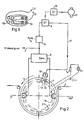
- head wheel 1 shows a head wheel disk or a head drum 1, hereinafter referred to as head wheel, with two magnetic heads 2 and 3.
- a magnetic tape 4 is placed around the head wheel 1.
- the head wheel 1 rotates in the direction of 5.
- Fields in the magnetic tape 4 induce voltages in the magnetic heads 2 and 3, which are given to a demodulator 6 via lines.
- the demodulator 6 demodulates the signals coming from the magnetic tape 4 and supplies demodulated signals to the output 7.
- a video signal can be tapped at output 7.
- a synchronous separation stage 8 synchronization words, hereinafter called synchronous words, are filtered out. These synchronous words are forwarded to a controller 9.
- the controller 9 controls a head wheel control 11 via an amplifier 10.
- Two conductors 12 and 13 are arranged parallel to the axis of rotation of the head wheel 1.
- the conductors 12 and 13 are permanently installed in the chassis of the video recorder, hereinafter referred to as the head wheel environment.
- An AC voltage source 15 supplies the conductors 12 and 13 with an alternating current I1 via a limiting resistor 14.
- the conductors 12 and 13 are elongated.
- the arrow direction 25 indicates the current direction.
- the current I1 flows through the conductor 12 in the direction of the drawing plane and the conductor 13 in the direction out of the drawing plane.
- the current I1 flows through the two conductors 12, 13 in the opposite direction, that is to say in the opposite direction, so that an electrical field is formed around the conductors 12, 13 with a minimal field strength between the two conductors.
- a head position circuit 16 separates pulses from the signals coming from the magnetic heads 2 and 3. These pulses are induced by conductors 12 and 13. The pulses are passed on from the head position circuit 16 to the controller 9 via the line 17.
- the controller 9 compares the synchronous words coming from the synchronous separation 8 with the head position pulses and regulates the head wheel control 11 on the basis of the synchronous words and the pulses.
- FIG. 2 shows the two elongated conductors 12 and 13 fixedly installed in the head wheel 1 parallel to the axis of rotation of the head wheel 1.
- the conductors 12 and 13 are supplied by the AC voltage source 15 and supplied with a current I2 via a limiting resistor 14.
- the two conductors 12 and 13 are connected to the voltage source and the limiting resistor 14 via slip rings 19 and 20 and via contact wipers.
- the magnetic heads 2 and 3 and the conductors 12 and 13 are advantageously arranged on the head wheel in two different planes, so that the conductors 12 and 13 do not influence the magnetic tape 4.
- the conductors 12 and 13 induce a voltage in the magnetic head 18.
- the voltage is passed on to the controller 9 via the line 17.
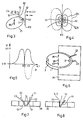
- FIG. 3 shows a magnetic head 2 on a head wheel track 21.
- the magnetic head 2 rotates on the head wheel track 21 and is displaceable in the direction of the axis of rotation 25.
- Two conductor loops 22 and 23 are arranged on the top wheel track 21.
- Each of the two conductor loops 22, 23 consists of two conductors 12 and 13 through which current flows.
- the conductor loop 23 is arranged parallel to the axis of rotation 25.
- the conductor loop 22 extends over a stroke region of the top wheel track 21.
- the conductor loop 22 forms an acute angle or a V-shaped arrangement with the conductor loop 23.
- the conductor loop 22 is arranged in such a way that it can induce a voltage in the magnetic head 2 over the entire stroke range of the knock wheel track 21.
- An exact determination of the head position 2 is possible via the conductor loop 23.
- a speed of the magnetic head 2 can be determined via the frequency of the induced pulses. Due to the inclined position of the conductor loop 22 relative to the conductor loop 23, different distances between the conductor loops 22 and 23 are predetermined.
- a height shift of the top wheel track in the direction of the axis of rotation 25 over a stroke range can be calculated from the different distances between the conductor tracks 22, 23.
- the stroke range is used to sequentially scan several parallel longitudinal tracks, which are arranged in blocks on a magnetic tape, over a height, which corresponds to the width of a magnetic tape.
- Fig. 4 shows two atomic conductors 12 and 13, which build up an electric field with the field lines 24.
- the two electrical conductors 12 and 13 are arranged on a top wheel track 21. Doing a mathematical quadrature or amount formation, which corresponds to an electrical rectification, this electrical field is minimal at location X0. See also (equation (4) on page 280 in) G. Joos, textbook of theoretical physics, eighth edition, Leipzig 1954, Akademiscbe publishing company Geest & Portig K.-G.
- FIG. 5 shows an induced voltage U after rectification, which is induced in a magnetic head on the head wheel path 21 at the point X0 in a magnetic head. Viewing with a time abscissa and a time to is also possible. Due to the voltage difference between U1 and U0 in the vicinity of point X0 an exact determination of the phase or the angular position of the heads 2, 3 or the head position on a head wheel track 21 is possible. The electric field has a strong gradient in the vicinity of X0. The induced voltage changes its sign at point X0. For a good transmission, the frequency of the polarity change of the currents I1-I4 with approximately the resonance frequency of a head / transmission system must be selected. That means choosing a frequency at which the system of head, equalizer and amplifier reacts most sensitively.
- Fig. 6 shows the head wheel 1 with the two magnetic heads 2 and 3, which is movably mounted in both directions 26 and 27 in the direction of the axis of rotation 25.
- the two conductor loops 22 and 23 are permanently installed in the head wheel environment 26.
- FIG 7 shows the top wheel environment 26 with the two conductor loops 22 and 23.
- Each conductor loop 22 and 23 has conductors 12 and 13.
- the current loop I1 flows through the conductor loop 22 and the current 12 flows through the conductor loop 23.
- FIG. 8 shows a V-shaped arrangement with a conductor loop 22.
- Each conductor 12 and 13 forms a V-shaped arrangement.
- a conductor loop 22 through which a current I1 flows is necessary for this V-shaped arrangement.
- Fig. 9 shows several conductors 12 and 13 in a coil-shaped arrangement.
- the distance s between the two conductors is of the order of the distance d between each of the conductors 12 and 13 and the heads 2, 3.
- the distances s and d are small compared to the length of the circumference of the top wheel track.
- the distance s between the two conductors is ideally zero.
Abstract
Description
Die Erfindung betrifft ein Gerät, insbesondere einen Videorecorder, gemäß dem Oberbegriff des Patentspruchs 1.The invention relates to a device, in particular a video recorder, according to the preamble of patent claim 1.
Aus der DE-A-31 15 670 ist ein Verfahren bekannt, die Winkellage der Magnetköpfe zum Band zu bestimmen. Eine Kopfradscheibe enthält neben den beiden rotierenden Magnetköpfen zwei rotierende Permanentmagnete, die während der Rotation in einem stationären Kopf oder in einer stationären Spule außerhalb des Kopfes, fest eingebaut in einer Kopfradumgebung, Impulse wechselnder Polarität erzeugen. Die Impulse dienen als Kriterium für die jeweilige Stellung und Geschwindigkeit der Kopfradscheibe (Seite 6, erster Absatz).From DE-A-31 15 670 a method is known for determining the angular position of the magnetic heads relative to the tape. In addition to the two rotating magnetic heads, a head wheel disc contains two rotating permanent magnets which, during rotation in a stationary head or in a stationary coil outside the head, permanently installed in a head wheel environment, generate pulses of alternating polarity. The impulses serve as a criterion for the respective position and speed of the top wheel disc (
Der Erfindung liegt die Aufgabe zugrunde, eine Anordnung zu schaffen, die die Anzeige der Winkelposition der Kopfradscheibe verbessert. Die Aufgabe wird durch die im Patentansprüche 1 angegebenen Merkmale gelöst. Verteilhafte Weiter-bildungen der Erfindung sind in abhängigen Ansprüchen angegeben.The invention has for its object to provide an arrangement that improves the display of the angular position of the head wheel disc. The object is achieved by the features specified in patent claims 1. Distributive developments of the invention are specified in dependent claims.
Es ist auch eine Kopfradanordnung bekannt (US-A-4 025 934), bei der dem Kopfrad ein Geber für hohe Frequenzen mit zwei nebeneinander liegenden Leitern zugeordnet ist. Als Indikator dient dabei eine rotierende archimedische Spirale aus Metall, die zwischen dem Geber und dem Fühler in der Funktion einer Empfangspule angeordnet ist. Die zusätzliche Ausnutzung der für die eigentliche Signalabtastung vorgesehenen Magnetköpfe als Fühler in dem Sinne, daß den Magnetköpfen neben dem Nutzsignal im Verlauf einer Umdrehung auch das Signal des Gebers zugeführt ist, ist dort jedoch nicht vorgesehen.A head wheel arrangement is also known (US-A-4 025 934), in which the head wheel is assigned a transmitter for high frequencies with two conductors lying next to one another. A rotating Archimedean spiral made of metal serves as an indicator and is arranged between the transmitter and the sensor in the function of a receiving coil. The additional use of the magnetic heads provided for the actual signal scanning as sensors in the sense that the magnetic heads are supplied with the useful signal in the course of one revolution and the signal from the encoder is not provided there.
Zum besseren Verständnis der Erfindung werden nachstehend Ausführungsbeispiele anhand von Zeichnungen näher erläutert. Es zeigen:
- Fig. 1 einen Geber an einer Kopfradscheibe,
- Fig. 2 einen Geber auf einer Kopfradscheibe,
- Fig. 3 eine Schemazeichnung für zwei Geber an einer Kopfradscheibe,
- Fig. 4 das Magnetfeld eines Gebers,
- Fig. 5 eine von einem Geber in einem Magnetkopf induzierte Spannung,
- Fig. 6 einen Geber in einer Kopfradumgebung,
- Fig. 7 eine V-förmige Anordnung mit zwei Leiterschleifen,
- Fig. 8 eine V-förmige Anordnung mit einer Leiterschleife,
- Fig. 9 eine weitere Anordnung von Leitern und
- Fig. 10 GröBenverhältnisse.
- 1 shows a sensor on a head wheel disc,
- 2 a sensor on a head wheel disc,
- 3 is a schematic drawing for two sensors on a head wheel disc,
- 4 the magnetic field of a sensor,
- 5 shows a voltage induced by a sensor in a magnetic head,
- 6 shows an encoder in a head wheel environment,
- 7 shows a V-shaped arrangement with two conductor loops,
- 8 shows a V-shaped arrangement with a conductor loop,
- Fig. 9 shows another arrangement of conductors and
- Fig. 10 size ratios.
Fig. 1 zeigt eine Kopfradscheibe oder eine Kopftrommel 1, im folgenden Kopfrad genannt, mit zwei Magnetköpfen 2 und 3. Um das Kopfrad 1 ist ein Magnetband 4 gelegt. Das Kopfrad 1 rotiert in Richtung 5. Felder im Magnetband 4 induzieren in den Magnetköpfen 2 und 3 Spannungen, die über Leitungen zu einem Demodulator 6 gegeben werden. Der Demodulator 6 demoduliert die vom Magnetband 4 kommenden Signale und führt demodulierte Signale dem Ausgang 7 zu. Am Ausgang 7 kann ein Videosignal abgegriffenwerden. In einer Synchrontrennungsstufe 8 werden Synchronisationsworter, im folgenden Synchronwörter genannt, herausgefiltert. Diese Synchronwörter werden zu einer Steuerung 9 weitergeleitet. Die Steuerung 9 steuert über einen Verstärker 10 eine kopfradregelung 11. Parallel zur Rotationsachse des Kopfrades 1 sind zwei Leiter 12 und 13 angeordnet. Die Leiter 12 und 13 sind fest im Chassis des Videorecorders, im folgenden Kopfradumgebung genannt, eingebaut. Eine Wechselspannungsquelle 15 versorgt die Leiter 12 und 13 über einen Begrenzungswiderstand 14 mit einem Wechselstrom I1. Die Leiter 12 und 13 sind länglich ausgebildet. Die Pfeilrichtung 25 gibt die Stromrichtung an. Der Strom I1 durchfließt den Leiter 12 in Richtung in die Zeichnungsebene hinein und den Leiter 13 in Richtung aus der Zeichnungsebene heraus. Der Strom I1 durchfließt die beiden Leiter 12,13 in entgegengesetzter Richtung, also im Gegensinn, so daß sich um die Leiter 12,13 ein elektrisches Feld mit einer minimalen Feldstärke zwischen den beiden Leitern ausbildet. Eine Kopfpositions-schaltung 16 trennt Impulse aus den von den Magnetköpfen 2 und 3 kommenden Signalen heraus. Diese Impulse werden von den Leitern 12 und 13 induziert. Die Impulse werden von der Kopfpositionsschaltung 16 über die Leitung 17 zur Steuerung 9 weitergegeben. Die Steuerung 9 vergleicht die von der Synchrontrennung 8 kommenden Synchronwörter mit den Kopfpositionsimpulsen und regelt aufgrund der Synchronwörter und der Impulse die Kopfradregelung 11.1 shows a head wheel disk or a head drum 1, hereinafter referred to as head wheel, with two
Fig. 2 zeigt die beiden länglichen Leiter 12 und 13 parallel zur Rotationsachse des Kopfrades 1 fest eingebaut in dem Kopfrad 1. Die Leiter 12 und 13 werden von der Wechselspannungsquelle 15 und über einen Begrenzungswiderstand 14 mit einem Strom I2 versorgt. Die beiden Leiter 12 und 13 sind über Schleifringe 19 und 20 und über Kontaktschleifer mit der Spannungsguelle und den Begrenzungswiderstand 14 verbunden. Vorteilhaft sind die Magnetköpfe 2 und 3 und die Leiter 12 und 13 auf dem Kopfrad in zwei verschiedenen Ebenen angeordnet, so daß die Leiter 12 und 13 das Magnetband 4 nicht beeinflussen. Während der Rotation des Kopfrades 1 induzieren die Leiter 12 und 13 eine Spannung in dem Magnetkopf 18. Die Spannung wird über die Leitung 17 zur Steuerung 9 weitergegeben.FIG. 2 shows the two
Fig. 3 zeigt einen Magnetkopf 2 auf einer Kopfradbahn 21. Der Magnetkopf 2 rotiert auf der Kopfradbahn 21 und ist in Richtung der Rotationsachse 25 verschiebbar. An der Kopfradbahn 21 sind zwei Leiterschleifen 22 und 23 angeordnet. Jede der beiden Leiterschleifen 22,23 besteht aus zwei stromdurchflossenen Leitern 12 und 13. Die Leiterschleife 23 ist parallel der Rotationsachse 25 angeordnet. Die Leiterschleife 22 erstreckt sich über einen Hubbereich der Kopfradbahn 21. Die Leiterschleife 22 bildet mit der Leiterschleife 23 einen spitzen Winkel bzw. eine V-förmige Anordnung. Die Leiterschleife 22 ist so angeordnet, daß sie über den gesamten Hubbereich der Ropfradbahn 21 eine Spannung in dem Magnetkopf 2 induzieren kann. Über die Leiterschleife 23 ist eine genaue Bestimmung der Kopfposition 2 möglich. Über die Häufigkeit der induzierten Impulse kann eine Geschwindigkeit des Magnetkopfes 2 bestimmt werden. Durch die Schräglage der Leiterschleife 22 zur Leiterschleife 23 sind verschiedene Abstände zwischen den Leiterschleifen 22 und 23 vorgegeben. Aus den verschiedenen Abständen zwischen den Leiterbahnen 22,23 ist eine Höhenverschiebung der Kopfradbahn in Richtung der Rotationsachse 25 über einen Hubbereich berechenbar. Der Hubbereich dient dazu, um mehrere parallele Längsspuren, die blockweise auf einem Magnetband angeordnet sind, sequentiell über eine Höhe, das entspricht der Breite eines Magnetbandes, abzutasten.3 shows a
Fig. 4 zeigt zwei atromdurchflossene Leiter 12 und 13, die ein elektrisches Feld mit den Feldlinien 24 aufbauen. Die beiden elektrischen Leiter 12 und 13 sind an einer Kopfradbahn 21 angeordnet. Mach einer mathematischen Quadratur oder Betragsbildung, das entspricht einer elektrischen Gleichrichtung, ist am Ort X0 dieses elektrische Feld minimal. Siehe dazu auch (Gleichung (4) auf Seite 280 in) G. Joos, Lehrbuch der theoretischen Physik, achte Auflage, Leipzig 1954, Akademiscbe Verlagsgesellschaft Geest & Portig K.-G.Fig. 4 shows two
Fig. 5 zeigt eine induzierte Spannung U nach einer Gleichrichtung, die in einem Magnetkopf auf der Kopfradbahn 21 an der Stelle X0 in einem Magnetkopf induziert ist. Eine betrachtung mit zeitlicher Abszisse und einem Zeitpunkt to ist auch möglich. Durch den Spannungsunterschied zwischen U1 und U0 in der Umgebung der Stelle X0 ist eine genaue bestimmung der Phasenbzw. der Winkellage der Köpfe 2,3 oder der Kopfposition auf einer Kopfradbahn 21 möglich. Das elektrische Feld weist in der Umgebung von X0 einen starken Gradienten auf. Die induzierte Spannung wechselt an der Stelle X0 ihr Vorzeichen. Für eine gute Übertragung ist die Frequenz des Polaritätswechsels der Ströme I1 - I4 mit etwa Resonanzfrequenz eines Kopf/Übertragungssystems zu wählen. Das heiBt eine Frequenz so zu wählen, bei der das System aus Kopf, Entzerrer und Verstärker am empfindlichsten reagiert.5 shows an induced voltage U after rectification, which is induced in a magnetic head on the
Fig. 6 zeigt das Kopfrad 1 mit den beiden Magnetköpfen 2 und 3, das in Richtung der Rotationsachse 25 in beide Richtungen 26 und 27 bewegbar gelagert ist. Um die jeweilige Stellung des Kopfrades 1 zu einer Umgebung 26 zu kennzeichnen, sind die beiden Leiterschleifen 22 und 23 fest in die Kopfradumgebung 26 eingebaut.Fig. 6 shows the head wheel 1 with the two
Fig. 7 zeigt die Kopfradumgebung 26 mit den beiden Leiterschleifen 22 und 23. Jede Leiterschleife 22 bzw. 23 weist Leiter 12 und 13 auf. Die Leiterschleife 22 wird vom Strom I1, die Leiterschleife 23 vom Strom 12 durchflossen.7 shows the
Fig. 8 zeigt eine V-förmige Anordnung mit einer Leiterschleife 22. Jeder Leiter 12 und 13 bildet eine V-förmige Anordnung. Für diese V-förmige Anordnung ist eine Leiterschleife 22 nötig, die von einem Strom I1 durchflossen ist.8 shows a V-shaped arrangement with a
Fig. 9 zeigt mehrere Leiter 12 und 13 in einer spulenförmigen Anordnung.Fig. 9 shows
Fig. 10 zeigt die Leiter 12 und 13. Der Abstand s zwischen den beiden Leitern liegt in der Größenordnung des Abstandes d zwischen jedem der Leiter 12 und 13 und den Köpfen 2,3. Die Abstände s und d sind klein gegenüber der Länge des Umfanges der Kopfradbahn. Der Abstand s zwischen den beiden Leitern beträgt im Idealfall Null.10 shows the
Claims (8)
Priority Applications (1)
| Application Number | Priority Date | Filing Date | Title |
|---|---|---|---|
| AT87102225T ATE68304T1 (en) | 1986-02-26 | 1987-02-17 | DEVICE, IN PARTICULAR VIDEO RECORDER. |
Applications Claiming Priority (2)
| Application Number | Priority Date | Filing Date | Title |
|---|---|---|---|
| DE19863606091 DE3606091A1 (en) | 1986-02-26 | 1986-02-26 | DEVICE, ESPECIALLY VIDEO RECORDER |
| DE3606091 | 1986-02-26 |
Publications (2)
| Publication Number | Publication Date |
|---|---|
| EP0234482A1 EP0234482A1 (en) | 1987-09-02 |
| EP0234482B1 true EP0234482B1 (en) | 1991-10-09 |
Family
ID=6294918
Family Applications (1)
| Application Number | Title | Priority Date | Filing Date |
|---|---|---|---|
| EP87102225A Expired - Lifetime EP0234482B1 (en) | 1986-02-26 | 1987-02-17 | Apparatus, particularly video tape recorder |
Country Status (8)
| Country | Link |
|---|---|
| US (1) | US4930025A (en) |
| EP (1) | EP0234482B1 (en) |
| JP (1) | JPS62204460A (en) |
| KR (1) | KR870008300A (en) |
| AT (1) | ATE68304T1 (en) |
| DE (2) | DE3606091A1 (en) |
| ES (1) | ES2026140T3 (en) |
| GR (1) | GR3003532T3 (en) |
Families Citing this family (5)
| Publication number | Priority date | Publication date | Assignee | Title |
|---|---|---|---|---|
| DE3829182A1 (en) * | 1988-08-29 | 1990-03-08 | Broadcast Television Syst | MAGNETIC TAPE DEVICE FOR RECORDING AND PLAYING BACK DATA DATA |
| KR930005877B1 (en) * | 1988-11-30 | 1993-06-25 | 주식회사 금성사 | Electron gun for color display tube |
| US5745316A (en) * | 1991-09-20 | 1998-04-28 | Deutsche Thomson Brandt Gmbh | Phase detector for a recorder/player using a conducting loop driven by a winding strand of the head drum motor |
| DE4131278A1 (en) * | 1991-09-20 | 1993-03-25 | Thomson Brandt Gmbh | RECORDER WITH DRIVE PHASE DETECTOR |
| CN1068449C (en) * | 1996-01-17 | 2001-07-11 | 三星电子株式会社 | Magnetic head position detector for magnetic tape recording equipment |
Family Cites Families (14)
| Publication number | Priority date | Publication date | Assignee | Title |
|---|---|---|---|---|
| GB931752A (en) * | 1960-08-15 | 1963-07-17 | Bush And Rank Cintel Ltd | Improvements in rotary-head magnetic recording and reproducing equipment |
| BE668533A (en) * | 1964-08-19 | |||
| AT278177B (en) * | 1968-04-01 | 1970-01-26 | Philips Nv | Device for obtaining a pulse train |
| DE1774502C3 (en) * | 1968-07-03 | 1974-02-14 | Siemens Ag, 1000 Berlin U. 8000 Muenchen | Arrangement for track selection control of the read / write heads in a magnetic disk storage system |
| DE1952369B2 (en) * | 1969-10-17 | 1971-10-21 | Blaupunkt-Werke Gmbh, 3200 Hildesheim | ARRANGEMENT FOR ADJUSTING VIDEO HEADS ON A HEADMARK |
| DE2137918A1 (en) * | 1971-07-23 | 1973-02-08 | Siemens Ag | DC-LOCATED ELECTRICAL MACHINE, IN PARTICULAR REACTIVE POWER MACHINE |
| JPS5151215Y2 (en) * | 1972-10-20 | 1976-12-08 | ||
| AT322642B (en) * | 1973-08-01 | 1975-05-26 | Philips Nv | RECORDING AND PLAYBACK DEVICE |
| DE2521163C2 (en) * | 1975-05-13 | 1977-06-16 | Frieseke & Hoepfner Gmbh | DEVICE FOR DETERMINING A SIZE CORRESPONDING TO THE SPEED OR THE ROTATION ANGLE OF AN AXIS |
| JPS51138410A (en) * | 1975-05-26 | 1976-11-30 | Sony Corp | Method of recording and reproducing signal |
| DE2751180C2 (en) * | 1977-11-16 | 1979-11-15 | Grundig E.M.V. Elektro-Mechanische Versuchsanstalt Max Grundig, 8510 Fuerth | Method and arrangement for the interference-free display of still images |
| DE2901676A1 (en) * | 1979-01-17 | 1980-08-14 | Papst Motoren Kg | COLLECTORLESS DC MOTOR |
| DE3115670A1 (en) * | 1981-04-18 | 1982-11-04 | Licentia Patent-Verwaltungs-Gmbh, 6000 Frankfurt | Video recorder with helical-track recording |
| JPS6035317U (en) * | 1983-08-18 | 1985-03-11 | アルプス電気株式会社 | magnetic head |
-
1986
- 1986-02-26 DE DE19863606091 patent/DE3606091A1/en not_active Withdrawn
-
1987
- 1987-02-13 JP JP62029951A patent/JPS62204460A/en active Pending
- 1987-02-17 EP EP87102225A patent/EP0234482B1/en not_active Expired - Lifetime
- 1987-02-17 ES ES198787102225T patent/ES2026140T3/en not_active Expired - Lifetime
- 1987-02-17 AT AT87102225T patent/ATE68304T1/en not_active IP Right Cessation
- 1987-02-17 DE DE8787102225T patent/DE3773504D1/en not_active Expired - Fee Related
- 1987-02-26 KR KR870001652A patent/KR870008300A/en not_active Application Discontinuation
-
1989
- 1989-01-17 US US07/298,203 patent/US4930025A/en not_active Expired - Fee Related
-
1992
- 1992-01-08 GR GR920400005T patent/GR3003532T3/el unknown
Also Published As
| Publication number | Publication date |
|---|---|
| JPS62204460A (en) | 1987-09-09 |
| ES2026140T3 (en) | 1992-04-16 |
| GR3003532T3 (en) | 1993-03-16 |
| DE3606091A1 (en) | 1987-08-27 |
| DE3773504D1 (en) | 1991-11-14 |
| ATE68304T1 (en) | 1991-10-15 |
| EP0234482A1 (en) | 1987-09-02 |
| US4930025A (en) | 1990-05-29 |
| KR870008300A (en) | 1987-09-25 |
Similar Documents
| Publication | Publication Date | Title |
|---|---|---|
| DE2907797C2 (en) | ||
| DE4437289C2 (en) | Magnetic recording disk, associated disk drive tracking system, and associated method | |
| DE2011222C3 (en) | Arrangement for determining coordinates on a surface | |
| DE2752027A1 (en) | ARRANGEMENT FOR GUIDING A TRACK-FREE VEHICLE | |
| DE112008001432T5 (en) | Linear motor position detection system | |
| DE102012204917A1 (en) | Position detecting device and method for detecting a position of a movable element of a driving device | |
| DE112007001939T5 (en) | Method for processing coder signals | |
| DE3308352A1 (en) | MAGNETIC DETECTOR DEVICE | |
| DE4344494C2 (en) | Method and device for measuring an axis rotation | |
| DE2350990A1 (en) | PROCESS AND DEVICE FOR PHASE-SENSITIVE COINS TESTING | |
| DE3112886A1 (en) | METHOD FOR DETECTING AN EDGE OF A MAGNETIC MEDIUM AND DEVICE FOR IMPLEMENTING THE METHOD | |
| DE3808198A1 (en) | DEVICE FOR RECORDING / PLAYING BACK A DIGITAL SIGNAL | |
| DE3303961A1 (en) | Device for the incremental detection of the position of a magnetically levitated vehicle | |
| EP0234482B1 (en) | Apparatus, particularly video tape recorder | |
| DE3231558C2 (en) | ||
| DE3240478C2 (en) | ||
| DE2454522A1 (en) | MAGNETORESISTIVE ELEMENT | |
| DE3040316C2 (en) | Method and device for contactless measurement of direct and alternating currents, in particular of instantaneous current values | |
| DE3418526A1 (en) | METHOD AND ARRANGEMENT FOR DETECTING ERROR SIGNALS IN A MAGNETIC DISK STORAGE AND TEST MAGNETIC DISK THEREFOR | |
| DE3836508A1 (en) | DEVICE FOR DETECTING THE SPEED OF A MOVING BODY | |
| DE19646056C2 (en) | Device for measuring the speed of a body rotating about an axis of rotation | |
| DE2929964C2 (en) | Process for the compensation of magnetic interference fields from objects by means of magnetic self-protection systems | |
| EP0204956B1 (en) | Apparatus, especially a video recorder | |
| DE2946559A1 (en) | Automatic path control of road vehicle - has sensors in vehicle reacting to signal in conductor set into road surface | |
| DE19837331B4 (en) | Method and device for measuring a rotational movement |
Legal Events
| Date | Code | Title | Description |
|---|---|---|---|
| PUAI | Public reference made under article 153(3) epc to a published international application that has entered the european phase |
Free format text: ORIGINAL CODE: 0009012 |
|
| AK | Designated contracting states |
Kind code of ref document: A1 Designated state(s): AT BE CH DE ES FR GB GR IT LI LU NL SE |
|
| 17P | Request for examination filed |
Effective date: 19880205 |
|
| 17Q | First examination report despatched |
Effective date: 19900511 |
|
| GRAA | (expected) grant |
Free format text: ORIGINAL CODE: 0009210 |
|
| AK | Designated contracting states |
Kind code of ref document: B1 Designated state(s): AT BE CH DE ES FR GB GR IT LI LU NL SE |
|
| REF | Corresponds to: |
Ref document number: 68304 Country of ref document: AT Date of ref document: 19911015 Kind code of ref document: T |
|
| ITF | It: translation for a ep patent filed |
Owner name: BARZANO' E ZANARDO MILANO S.P.A. |
|
| REF | Corresponds to: |
Ref document number: 3773504 Country of ref document: DE Date of ref document: 19911114 |
|
| ET | Fr: translation filed | ||
| GBT | Gb: translation of ep patent filed (gb section 77(6)(a)/1977) | ||
| PGFP | Annual fee paid to national office [announced via postgrant information from national office to epo] |
Ref country code: LU Payment date: 19920130 Year of fee payment: 6 |
|
| PGFP | Annual fee paid to national office [announced via postgrant information from national office to epo] |
Ref country code: SE Payment date: 19920205 Year of fee payment: 6 |
|
| PGFP | Annual fee paid to national office [announced via postgrant information from national office to epo] |
Ref country code: GB Payment date: 19920211 Year of fee payment: 6 |
|
| PG25 | Lapsed in a contracting state [announced via postgrant information from national office to epo] |
Ref country code: ES Free format text: LAPSE BECAUSE OF EXPIRATION OF PROTECTION Effective date: 19920218 |
|
| PGFP | Annual fee paid to national office [announced via postgrant information from national office to epo] |
Ref country code: BE Payment date: 19920219 Year of fee payment: 6 |
|
| PGFP | Annual fee paid to national office [announced via postgrant information from national office to epo] |
Ref country code: GR Payment date: 19920225 Year of fee payment: 6 |
|
| PGFP | Annual fee paid to national office [announced via postgrant information from national office to epo] |
Ref country code: CH Payment date: 19920228 Year of fee payment: 6 |
|
| PGFP | Annual fee paid to national office [announced via postgrant information from national office to epo] |
Ref country code: NL Payment date: 19920229 Year of fee payment: 6 |
|
| REG | Reference to a national code |
Ref country code: ES Ref legal event code: FG2A Ref document number: 2026140 Country of ref document: ES Kind code of ref document: T3 |
|
| EPTA | Lu: last paid annual fee | ||
| PLBE | No opposition filed within time limit |
Free format text: ORIGINAL CODE: 0009261 |
|
| STAA | Information on the status of an ep patent application or granted ep patent |
Free format text: STATUS: NO OPPOSITION FILED WITHIN TIME LIMIT |
|
| 26N | No opposition filed | ||
| PG25 | Lapsed in a contracting state [announced via postgrant information from national office to epo] |
Ref country code: FR Effective date: 19921030 |
|
| PG25 | Lapsed in a contracting state [announced via postgrant information from national office to epo] |
Ref country code: DE Effective date: 19921103 |
|
| REG | Reference to a national code |
Ref country code: GR Ref legal event code: FG4A Free format text: 3003532 |
|
| REG | Reference to a national code |
Ref country code: FR Ref legal event code: ST |
|
| PGFP | Annual fee paid to national office [announced via postgrant information from national office to epo] |
Ref country code: AT Payment date: 19930210 Year of fee payment: 7 |
|
| PG25 | Lapsed in a contracting state [announced via postgrant information from national office to epo] |
Ref country code: LU Free format text: LAPSE BECAUSE OF NON-PAYMENT OF DUE FEES Effective date: 19930217 Ref country code: GB Effective date: 19930217 |
|
| PG25 | Lapsed in a contracting state [announced via postgrant information from national office to epo] |
Ref country code: SE Effective date: 19930218 |
|
| PG25 | Lapsed in a contracting state [announced via postgrant information from national office to epo] |
Ref country code: LI Effective date: 19930228 Ref country code: CH Effective date: 19930228 Ref country code: BE Effective date: 19930228 |
|
| BERE | Be: lapsed |
Owner name: DEUTSCHE THOMSON-BRANDT G.M.B.H. Effective date: 19930228 |
|
| PG25 | Lapsed in a contracting state [announced via postgrant information from national office to epo] |
Ref country code: GR Free format text: THE PATENT HAS BEEN ANNULLED BY A DECISION OF A NATIONAL AUTHORITY Effective date: 19930831 |
|
| PG25 | Lapsed in a contracting state [announced via postgrant information from national office to epo] |
Ref country code: NL Effective date: 19930901 |
|
| GBPC | Gb: european patent ceased through non-payment of renewal fee |
Effective date: 19930217 |
|
| NLV4 | Nl: lapsed or anulled due to non-payment of the annual fee | ||
| REG | Reference to a national code |
Ref country code: CH Ref legal event code: PL |
|
| PG25 | Lapsed in a contracting state [announced via postgrant information from national office to epo] |
Ref country code: AT Effective date: 19940217 |
|
| REG | Reference to a national code |
Ref country code: GR Ref legal event code: MM2A Free format text: 3003532 |
|
| EUG | Se: european patent has lapsed |
Ref document number: 87102225.7 Effective date: 19930912 |
|
| REG | Reference to a national code |
Ref country code: ES Ref legal event code: FD2A Effective date: 19991201 |
|
| PG25 | Lapsed in a contracting state [announced via postgrant information from national office to epo] |
Ref country code: IT Free format text: LAPSE BECAUSE OF NON-PAYMENT OF DUE FEES Effective date: 20050217 |