EP0234238B1 - Verfahren zur Herstellung eines folien- oder plattenförmigen Gebildes als Lagerwerkstoff für Gleitlager - Google Patents
Verfahren zur Herstellung eines folien- oder plattenförmigen Gebildes als Lagerwerkstoff für Gleitlager Download PDFInfo
- Publication number
- EP0234238B1 EP0234238B1 EP87100571A EP87100571A EP0234238B1 EP 0234238 B1 EP0234238 B1 EP 0234238B1 EP 87100571 A EP87100571 A EP 87100571A EP 87100571 A EP87100571 A EP 87100571A EP 0234238 B1 EP0234238 B1 EP 0234238B1
- Authority
- EP
- European Patent Office
- Prior art keywords
- lubricant
- bearing
- plastics material
- mould
- recesses
- Prior art date
- Legal status (The legal status is an assumption and is not a legal conclusion. Google has not performed a legal analysis and makes no representation as to the accuracy of the status listed.)
- Expired
Links
Images



Classifications
-
- F—MECHANICAL ENGINEERING; LIGHTING; HEATING; WEAPONS; BLASTING
- F16—ENGINEERING ELEMENTS AND UNITS; GENERAL MEASURES FOR PRODUCING AND MAINTAINING EFFECTIVE FUNCTIONING OF MACHINES OR INSTALLATIONS; THERMAL INSULATION IN GENERAL
- F16C—SHAFTS; FLEXIBLE SHAFTS; ELEMENTS OR CRANKSHAFT MECHANISMS; ROTARY BODIES OTHER THAN GEARING ELEMENTS; BEARINGS
- F16C33/00—Parts of bearings; Special methods for making bearings or parts thereof
- F16C33/02—Parts of sliding-contact bearings
- F16C33/04—Brasses; Bushes; Linings
- F16C33/24—Brasses; Bushes; Linings with different areas of the sliding surface consisting of different materials
-
- C—CHEMISTRY; METALLURGY
- C25—ELECTROLYTIC OR ELECTROPHORETIC PROCESSES; APPARATUS THEREFOR
- C25D—PROCESSES FOR THE ELECTROLYTIC OR ELECTROPHORETIC PRODUCTION OF COATINGS; ELECTROFORMING; APPARATUS THEREFOR
- C25D7/00—Electroplating characterised by the article coated
- C25D7/10—Bearings
-
- Y—GENERAL TAGGING OF NEW TECHNOLOGICAL DEVELOPMENTS; GENERAL TAGGING OF CROSS-SECTIONAL TECHNOLOGIES SPANNING OVER SEVERAL SECTIONS OF THE IPC; TECHNICAL SUBJECTS COVERED BY FORMER USPC CROSS-REFERENCE ART COLLECTIONS [XRACs] AND DIGESTS
- Y10—TECHNICAL SUBJECTS COVERED BY FORMER USPC
- Y10S—TECHNICAL SUBJECTS COVERED BY FORMER USPC CROSS-REFERENCE ART COLLECTIONS [XRACs] AND DIGESTS
- Y10S29/00—Metal working
- Y10S29/025—Method or apparatus with particular material
-
- Y—GENERAL TAGGING OF NEW TECHNOLOGICAL DEVELOPMENTS; GENERAL TAGGING OF CROSS-SECTIONAL TECHNOLOGIES SPANNING OVER SEVERAL SECTIONS OF THE IPC; TECHNICAL SUBJECTS COVERED BY FORMER USPC CROSS-REFERENCE ART COLLECTIONS [XRACs] AND DIGESTS
- Y10—TECHNICAL SUBJECTS COVERED BY FORMER USPC
- Y10S—TECHNICAL SUBJECTS COVERED BY FORMER USPC CROSS-REFERENCE ART COLLECTIONS [XRACs] AND DIGESTS
- Y10S29/00—Metal working
- Y10S29/029—Molding with other step
-
- Y—GENERAL TAGGING OF NEW TECHNOLOGICAL DEVELOPMENTS; GENERAL TAGGING OF CROSS-SECTIONAL TECHNOLOGIES SPANNING OVER SEVERAL SECTIONS OF THE IPC; TECHNICAL SUBJECTS COVERED BY FORMER USPC CROSS-REFERENCE ART COLLECTIONS [XRACs] AND DIGESTS
- Y10—TECHNICAL SUBJECTS COVERED BY FORMER USPC
- Y10S—TECHNICAL SUBJECTS COVERED BY FORMER USPC CROSS-REFERENCE ART COLLECTIONS [XRACs] AND DIGESTS
- Y10S29/00—Metal working
- Y10S29/048—Welding with other step
-
- Y—GENERAL TAGGING OF NEW TECHNOLOGICAL DEVELOPMENTS; GENERAL TAGGING OF CROSS-SECTIONAL TECHNOLOGIES SPANNING OVER SEVERAL SECTIONS OF THE IPC; TECHNICAL SUBJECTS COVERED BY FORMER USPC CROSS-REFERENCE ART COLLECTIONS [XRACs] AND DIGESTS
- Y10—TECHNICAL SUBJECTS COVERED BY FORMER USPC
- Y10S—TECHNICAL SUBJECTS COVERED BY FORMER USPC CROSS-REFERENCE ART COLLECTIONS [XRACs] AND DIGESTS
- Y10S384/00—Bearings
- Y10S384/90—Cooling or heating
- Y10S384/907—Bearing material or solid lubricant
-
- Y—GENERAL TAGGING OF NEW TECHNOLOGICAL DEVELOPMENTS; GENERAL TAGGING OF CROSS-SECTIONAL TECHNOLOGIES SPANNING OVER SEVERAL SECTIONS OF THE IPC; TECHNICAL SUBJECTS COVERED BY FORMER USPC CROSS-REFERENCE ART COLLECTIONS [XRACs] AND DIGESTS
- Y10—TECHNICAL SUBJECTS COVERED BY FORMER USPC
- Y10S—TECHNICAL SUBJECTS COVERED BY FORMER USPC CROSS-REFERENCE ART COLLECTIONS [XRACs] AND DIGESTS
- Y10S384/00—Bearings
- Y10S384/90—Cooling or heating
- Y10S384/909—Plastic
-
- Y—GENERAL TAGGING OF NEW TECHNOLOGICAL DEVELOPMENTS; GENERAL TAGGING OF CROSS-SECTIONAL TECHNOLOGIES SPANNING OVER SEVERAL SECTIONS OF THE IPC; TECHNICAL SUBJECTS COVERED BY FORMER USPC CROSS-REFERENCE ART COLLECTIONS [XRACs] AND DIGESTS
- Y10—TECHNICAL SUBJECTS COVERED BY FORMER USPC
- Y10S—TECHNICAL SUBJECTS COVERED BY FORMER USPC CROSS-REFERENCE ART COLLECTIONS [XRACs] AND DIGESTS
- Y10S384/00—Bearings
- Y10S384/90—Cooling or heating
- Y10S384/912—Metallic
-
- Y—GENERAL TAGGING OF NEW TECHNOLOGICAL DEVELOPMENTS; GENERAL TAGGING OF CROSS-SECTIONAL TECHNOLOGIES SPANNING OVER SEVERAL SECTIONS OF THE IPC; TECHNICAL SUBJECTS COVERED BY FORMER USPC CROSS-REFERENCE ART COLLECTIONS [XRACs] AND DIGESTS
- Y10—TECHNICAL SUBJECTS COVERED BY FORMER USPC
- Y10S—TECHNICAL SUBJECTS COVERED BY FORMER USPC CROSS-REFERENCE ART COLLECTIONS [XRACs] AND DIGESTS
- Y10S428/00—Stock material or miscellaneous articles
- Y10S428/922—Static electricity metal bleed-off metallic stock
- Y10S428/9335—Product by special process
- Y10S428/934—Electrical process
- Y10S428/935—Electroplating
-
- Y—GENERAL TAGGING OF NEW TECHNOLOGICAL DEVELOPMENTS; GENERAL TAGGING OF CROSS-SECTIONAL TECHNOLOGIES SPANNING OVER SEVERAL SECTIONS OF THE IPC; TECHNICAL SUBJECTS COVERED BY FORMER USPC CROSS-REFERENCE ART COLLECTIONS [XRACs] AND DIGESTS
- Y10—TECHNICAL SUBJECTS COVERED BY FORMER USPC
- Y10T—TECHNICAL SUBJECTS COVERED BY FORMER US CLASSIFICATION
- Y10T29/00—Metal working
- Y10T29/49—Method of mechanical manufacture
- Y10T29/49636—Process for making bearing or component thereof
- Y10T29/49705—Coating or casting
-
- Y—GENERAL TAGGING OF NEW TECHNOLOGICAL DEVELOPMENTS; GENERAL TAGGING OF CROSS-SECTIONAL TECHNOLOGIES SPANNING OVER SEVERAL SECTIONS OF THE IPC; TECHNICAL SUBJECTS COVERED BY FORMER USPC CROSS-REFERENCE ART COLLECTIONS [XRACs] AND DIGESTS
- Y10—TECHNICAL SUBJECTS COVERED BY FORMER USPC
- Y10T—TECHNICAL SUBJECTS COVERED BY FORMER US CLASSIFICATION
- Y10T29/00—Metal working
- Y10T29/49—Method of mechanical manufacture
- Y10T29/4998—Combined manufacture including applying or shaping of fluent material
- Y10T29/49982—Coating
-
- Y—GENERAL TAGGING OF NEW TECHNOLOGICAL DEVELOPMENTS; GENERAL TAGGING OF CROSS-SECTIONAL TECHNOLOGIES SPANNING OVER SEVERAL SECTIONS OF THE IPC; TECHNICAL SUBJECTS COVERED BY FORMER USPC CROSS-REFERENCE ART COLLECTIONS [XRACs] AND DIGESTS
- Y10—TECHNICAL SUBJECTS COVERED BY FORMER USPC
- Y10T—TECHNICAL SUBJECTS COVERED BY FORMER US CLASSIFICATION
- Y10T29/00—Metal working
- Y10T29/49—Method of mechanical manufacture
- Y10T29/4998—Combined manufacture including applying or shaping of fluent material
- Y10T29/49993—Filling of opening
-
- Y—GENERAL TAGGING OF NEW TECHNOLOGICAL DEVELOPMENTS; GENERAL TAGGING OF CROSS-SECTIONAL TECHNOLOGIES SPANNING OVER SEVERAL SECTIONS OF THE IPC; TECHNICAL SUBJECTS COVERED BY FORMER USPC CROSS-REFERENCE ART COLLECTIONS [XRACs] AND DIGESTS
- Y10—TECHNICAL SUBJECTS COVERED BY FORMER USPC
- Y10T—TECHNICAL SUBJECTS COVERED BY FORMER US CLASSIFICATION
- Y10T29/00—Metal working
- Y10T29/49—Method of mechanical manufacture
- Y10T29/49995—Shaping one-piece blank by removing material
-
- Y—GENERAL TAGGING OF NEW TECHNOLOGICAL DEVELOPMENTS; GENERAL TAGGING OF CROSS-SECTIONAL TECHNOLOGIES SPANNING OVER SEVERAL SECTIONS OF THE IPC; TECHNICAL SUBJECTS COVERED BY FORMER USPC CROSS-REFERENCE ART COLLECTIONS [XRACs] AND DIGESTS
- Y10—TECHNICAL SUBJECTS COVERED BY FORMER USPC
- Y10T—TECHNICAL SUBJECTS COVERED BY FORMER US CLASSIFICATION
- Y10T428/00—Stock material or miscellaneous articles
- Y10T428/12—All metal or with adjacent metals
- Y10T428/1234—Honeycomb, or with grain orientation or elongated elements in defined angular relationship in respective components [e.g., parallel, inter- secting, etc.]
-
- Y—GENERAL TAGGING OF NEW TECHNOLOGICAL DEVELOPMENTS; GENERAL TAGGING OF CROSS-SECTIONAL TECHNOLOGIES SPANNING OVER SEVERAL SECTIONS OF THE IPC; TECHNICAL SUBJECTS COVERED BY FORMER USPC CROSS-REFERENCE ART COLLECTIONS [XRACs] AND DIGESTS
- Y10—TECHNICAL SUBJECTS COVERED BY FORMER USPC
- Y10T—TECHNICAL SUBJECTS COVERED BY FORMER US CLASSIFICATION
- Y10T428/00—Stock material or miscellaneous articles
- Y10T428/12—All metal or with adjacent metals
- Y10T428/12486—Laterally noncoextensive components [e.g., embedded, etc.]
-
- Y—GENERAL TAGGING OF NEW TECHNOLOGICAL DEVELOPMENTS; GENERAL TAGGING OF CROSS-SECTIONAL TECHNOLOGIES SPANNING OVER SEVERAL SECTIONS OF THE IPC; TECHNICAL SUBJECTS COVERED BY FORMER USPC CROSS-REFERENCE ART COLLECTIONS [XRACs] AND DIGESTS
- Y10—TECHNICAL SUBJECTS COVERED BY FORMER USPC
- Y10T—TECHNICAL SUBJECTS COVERED BY FORMER US CLASSIFICATION
- Y10T428/00—Stock material or miscellaneous articles
- Y10T428/12—All metal or with adjacent metals
- Y10T428/12493—Composite; i.e., plural, adjacent, spatially distinct metal components [e.g., layers, joint, etc.]
- Y10T428/12535—Composite; i.e., plural, adjacent, spatially distinct metal components [e.g., layers, joint, etc.] with additional, spatially distinct nonmetal component
Definitions
- the invention relates to a method for producing a film or plate-shaped structure as a bearing material for plain bearings according to the preamble of claim 1.
- a carrier material e.g. a foil or plate made of steel
- a layer made of a bearing material e.g. Bronze
- a lubricant e.g. a mixture of polytetrafluoroethylene (PTFE) and lead, rolled in (see company name of Karl Schmidt GmbH, Neckarsulm).
- PTFE polytetrafluoroethylene
- the ratio of the load-bearing material surface to the lubricant-dispensing surface is largely predetermined by the choice of material and the sintering process and can therefore only be varied within narrow limits.
- the invention has for its object to provide a method for producing a structured film or plate-shaped structure with a freely selectable pattern as a bearing material for slide bearings, in which the minimum characteristic lateral dimensions of the load-bearing structures or the lubricant-releasing structures are in the World Cup range Structure height up to several 100 ⁇ m.
- the solution to this problem contained in claim 1 allows both metallic webs and metallic pins with lubricant introduced between them to be applied to the metallic carrier layer, the wall thickness of the metallic webs or the gap width of the lubricant-dispensing channels being a few J, Lm at one Height of several 100 ⁇ m. Due to the way in which the sample is produced, the ratio of the load-bearing area to the lubricant-dispensing area can also be specified in a targeted manner even in the case of abrasion. With parallel walls of the channels filled with lubricant, the ratio remains constant; in the case of walls tapering towards one another, this ratio varies in a targeted manner with the abrasion.
- the measure according to claim 4 makes it possible to use a different bearing material for the supporting bearing surface instead of an electrodepositable metal.
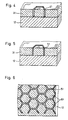
- FIGS. 1 to 6 show the production of a bearing material in which metallic pins for the supporting bearing surface, which are produced according to the LIGA process, are enclosed by channels which are connected to one another in a network and filled with a lubricant.
- FIGS. 7 to 9 show an example in which a film-like structure was produced using the electroplating technique and then connected to a metallic carrier material and filled with lubricant.
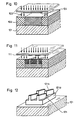
- FIGS. 10 to 15 show a third example of a bearing material, in which metering slots with widened lubrication pockets underneath were machined into the bearing surface.
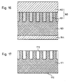
- FIGS. 16 and 17 show the production of a bearing material made of plastic with the aid of a metallic impression tool produced by X-ray depth lithography-galvanoplastic.
- FIG. 1 shows a section of a metallic layer 12 on which a layer 11 is made of a material whose properties can be changed by X-ray radiation
- a negative mold 21 is created with a pattern of depressions 22 complementary to the X-ray mask absorber structure, the depth of which corresponds to the thickness of the negative mold 21 (FIG. 2 ).
- the depressions 22 are then galvanically filled with a metal 13 using the metallic layer 12 as an electrode (FIG. 3). After the layer of metal 31 has been leveled, the remaining plastic of the negative mold 21 is removed (FIG. 4) and the resulting interstices 41 are filled with a lubricant 51 (FIG. 5).
- FIG. 6 shows a top view of the bearing material according to the invention for a slide bearing, consisting of the metallic layer 12 as the carrier material, metallic pins 61 for the load-bearing surface and the channels which enclose them in a network and which contain the lubricant 51.
- This bearing material has a high load-bearing capacity and good thermal conductivity due to the solid metallic pins and their large surface area.
- the lubricant supply is distributed over the bearing surface in accordance with the specified pattern, this distribution and thus the good sliding properties being retained even when abraded.
- FIG. 7 shows in section an impression tool 70 produced by X-ray lithography-galvanoplastic, consisting of microstructures 71 and a base plate 72 firmly connected to them, in engagement with an impression compound 73.
- the end faces of the microstructures 71 were previously covered with an easily removable, electrically conductive material 74 coated.
- a casting resin (Plexit M60 from Röhm, Darmstadt), to which 1 vol.% Of a desensitized, 50 percent benzoyl peroxide was added as hardener, is used as impression material 73.
- An internal release agent type PAT 665 from Würtz GmbH, Bingen-Sponsheim is also added to the casting resin in an amount of 4% by volume to facilitate demolding.
- the resulting negative mold is removed from the mold, consisting of a base body 81 with peg-shaped structures 82, which are surrounded by depressions 83 in a network. At the bottom of the depressions is the electrically conductive material 74, which serves as an electrode for galvanically filling the depressions 83 with bronze.
- a film-shaped structure 91 is obtained from metal with circular openings 92 (FIG. 9).
- the film-shaped structure 91 is connected by diffusion welding to a metallic layer 93 as a carrier material.
- the circular openings 92 are then filled with a lubricant 94.
- FIG. 10 shows a metallic layer 101, on which a layer 102 made of material whose properties can be changed by means of X-ray radiation (resist material) has been applied.
- Partial irradiation with synchrotron radiation 103 via an X-ray mask 104 and subsequent renewed irradiation with a second X-ray mask 111 (FIG. 11) with reduced penetration depth results in a partial removal of the resist material using the different material properties generated by the radiation, and a negative mold 121 consisting of bases 121 a and pins 121b thereon made of resist material.
- a metal 13 is then electrodeposited on the electrode 101 (FIG. 13), which embeds the base and pin.
- the pins 121 b and the base 121 a of the negative mold 121 are removed (FIG. 14) and replaced by a lubricant 151 (FIG. 15).
- the lubricant fills both the metering slots 152 and the lubrication pockets 153 connected to and underneath, which are widened compared to the slots 152.
- the embodiment with lubrication pockets 153 and metering slots 152 according to FIG. 15 can be combined with the embodiments according to FIGS. 6 and 9 on the same load-bearing layer 101 in order to optimize the lubrication and load-bearing capacity of the bearing.
- this combination offers an extended service life of the bearing without relubrication due to the high lubricant supply and, by choosing the metering slot size and / or using gelled lubricating oils as lubricants, enables optimally metered lubricant delivery.
- FIG. 16 shows in section a metal impression tool 160, which is produced by X-ray lithography and is galvanoplastic, and consists of microstructures 161 and a base plate 162 fixedly connected to them, in engagement with an impression compound 163, which is connected to a demolding aid 164.
- Typical injection molding compounds or casting resins used for plastic bearings can be used as impression compounds.
- the embodiment according to FIG. 17 has the advantage compared to conventional lubricated plastic bearings that a targeted metered lubrication of the surface is achieved and the permissible sliding speeds are thus increased.
- selective spreading of the surface can improve the spreading behavior of the bearing and thus increase the service life of the bearing.
- the intermediate spaces filled with lubricant have the shape of reticular, hexagonal prisms cylindrical bores or metering slots. Instead of this or in addition to this, it is of course also possible to make the spaces geometrically different, z. B. in the form of spiral grooves.
Landscapes
- Engineering & Computer Science (AREA)
- General Engineering & Computer Science (AREA)
- Chemical & Material Sciences (AREA)
- Mechanical Engineering (AREA)
- Chemical Kinetics & Catalysis (AREA)
- Electrochemistry (AREA)
- Materials Engineering (AREA)
- Metallurgy (AREA)
- Organic Chemistry (AREA)
- Sliding-Contact Bearings (AREA)
- Laminated Bodies (AREA)
- Manufacture Of Macromolecular Shaped Articles (AREA)
Description
- Die Erfindung betrifft ein Verfahren zur Herstellung eines folien- oder plattenförmigen Gebildes als Lagerwerkstoff für Gleitlager gemäß dem Oberbegriff von Anspruch 1.
- Aus der DE-PS 683 764 ist es bekannt, Zweimetall-Lagerschalen durch galvanischen Niederschlag einer Schicht des Lagermetalls oder der Lagerlegierung auf einen Hartmetallträger herzustellen. Derartige Lager sind jedoch nicht strukturiert und haben daher keine selbstschmierenden Eigenschaften.
- Für die Herstellung von selbstschmierenden Gleitlagern ist es bekannt, auf ein Trägermaterial, z.B. eine Folie oder eine Platte aus Stahl, eine Schicht aus einem Lagerwerkstoff, z.B. Bronze, in gesinterter Form aufzubringen. In diesen gesinterten und damit porösen Werkstoff wird ein Schmierstoff, z.B. eine Mischung aus Polytetrafluorethylen (PTFE) und Blei, eingewalzt (s. Firmschrift der Fa. Karl Schmidt GmbH, Neckarsulm). Dabei ist jedoch das Verhältnis von tragender Werkstofffläche zu Schmierstoff abgebender Fläche durch die Wahl des Werkstoffs und den Sinterprozeß weitgehend vorgegeben und kann daher nur in engen Grenzen variiert werden. Außerdem sind bedingt durch den Herstellungsprozeß unterschiedlich große Werkstoffflächenbereiche und gleichermaßen auch unterschiedliche große Schmierstoff abgebende Flächenbereiche statistisch verteilt. Dies hat zur Folge, daß in Teilbereichen entweder für die Schmierung oder für die Tragfähigkeit keine optimalen Bedingungen vorliegen.
- Aus der Druckschrift "Haus der Technik-Vortragsveröffentlichungen", Heft 269, 1971, Vulkan-Verlag Dr. W. Classen, Essen, S. 61-67, ist eine Lagerbuchse aus einer Kupfergußlegierung bekannt, bei der ein Festschmierstoff, der in Taschen oder anderen Vertiefungen in der Lauffläche angeordnet ist, die Schmierung übernimmt. Gemäß der US-PS 3 938 868 können auch keramische Werkstoffe als Lagermittel verwendet werden.
- Aus der DE-OS 22 34 428 ist es bekannt, zwischen den sich gegeneinander bewegenden Flächen eine perforierte Zwischenlage aus Metall, Kunststoff oder einem selbstschmierenden Material einzufügen und die Hohlräume mit Schmierstoff zu füllen. Auch können die Flächen selbst mit feinen Vertiefungen versehen werden, in dem die Oberfläche durch mechanische, chemische, elektrochemische oder elektrische Behandlungsverfahren ein Profil erhält, das überwalzt, überdreht oder überschliffen wird. Damit können Strukturen mit einem Muster von z.B. kreisförmigen oder kreuzförmigen Vertiefungen erzeugt werden, wobei der minimale Kantenabstand bzw. die Stegbreite etwa 0,1 mm bzw. 0,2' mm beträgt. In dieser Druckschrift wird ferner ausgeführt, daß es wichtig ist, die Hohlräume bzw. Vertiefungen dicht beieinander liegend anzuordnen. Mit den vorerwähnten Behandlungsverfahren lassen sich jedoch Strukturen mit noch geringerem Kantenabstand bzw. Stegbreite unter Berücksichtigung der erforderlichen Strukturhöhe nicht mehr realisieren.
- Der Erfindung liegt die Aufgabe zugrunde, ein Verfahren zur Herstellung eines strukturierten folien- oder plattenförmigen Gebildes bei frei wählbarem Muster als Lagerwerkstoff für Gleitlager vorzusehen, bei dem die minimalen charakteristischen Lateralabmessungen der tragendenden Strukturen bzw. der Schmierstoff abgebenden Strukturen im wm-Bereich liegen bei einer Strukturhöhe bis zu mehreren 100 µm.
- Die im Patentanspruch 1 enthaltene Lösung dieser Aufgabe gestattet es, sowohl metallische Stege als auch metallische Zapfen mit jeweils dazwischen eingebrachtem Schmierstoff auf der metallischen Trägerschicht aufzubringen, wobei die Wandstärke der metallischen Stege bzw. die Spaltweite der Schmierstoff abgebenden Kanäle wenige J,Lm beträgt bei einer Höhe von mehreren 100 µm. Durch die Art der Herstellung des Musters kann das Verhältnis von tragender zu Schmierstoff abgebender Fläche auch bei Abrieb gezielt vorgegeben werden. Bei parallelen Wänden der mit Schmierstoff gefüllten Kanäle bleibt das Verhältnis konstant; bei zueinander konisch verlaufenden Wänden variiert dieses Verhältnis in gezielter Weise mit dem Abrieb.
- Die Ansprüche 2 und 3 beinhalten vorteilhafte Weiterbildungen der Maßnahmen gemäß Anspruch 1.
- Die Maßnahme gemäß Anspruch 4 gestattet es, anstelle eines galvanisch abscheidbaren Metalls auch ein anderes Lagermaterial für die tragende Lageroberfläche einzusetzen.
- Die Herstellung von Mikrostrukturen auf röntgentiefenlithographischemWege bzw. der hiervon abgeleiteten Abformtechnik (LIGA-Verfahren) ist in dem Bereich KfK 3995, Nov. 1985, des Kernforschungszentrums Karlsruhe, auf den verwiesen wird, beschriebenen und dargestellt.
- Ausführungsbeispiele der Erfindung werden im folgenden anhand der Zeichnungen erläutert:
- Die Figuren 1 bis 6 zeigen die Herstellung eines Lagerwerkstoffs, bei dem metallische, nach dem LIGA-Verfahren hergestellte Zapfen für die tragende Lageroberfläche von netzförmig miteinander verbundenen und mit einem Schmierstoff ausgefüllten Kanälen umschlossen sind.
- Die Figuren 7 bis 9 zeigen ein Beispiel, bei dem ein folienförmiges Gebilde nach der Galvano-Abformtechnik hergestellt und sodann mit einem metallischen Trägermaterial verbunden und mit Schmierstoff gefüllt wurde.
- Die Figuren 10 bis 15 zeigen ein drittes Beispiel für einen Lagerwerkstoff, bei dem in die tragende Lageroberfläche Dosierschlitze mit darunter liegenden, verbreiterten Schmiertaschen eingearbeitet wurden.
- Die Figuren 16 und 17 zeigen die Herstellung eines Lagerwerkstoffs aus Kunststoff mit Hilfe eines auf röntgentiefenlithographisch-galvanoplastischem Wege hergestellten, metallischen Abformwerkzeuges.
- Figur 1 zeigt im Schnitt eine metallische Schicht 12, auf der eine Schicht 11 aus einem durch Röntgenstrahlung in seinen Eigenschaften veränderbarem
- Material (Resistmaterial) aufgebracht wurde. Durch partielles Bestrahlen mit Synchrotronstrahlung 13 über eine Röntgenmaske 14 und partielles Entfernen des Resistmaterials unter Ausnutzung der durch die Strahlung erzeugten unterschiedlichen Materialeigenschaften entsteht eine Negativform 21 mit einem zur Röngenmaskenabsorberstruktur komplementären Muster aus Vertiefungen 22, deren Tiefe der Dicke der Negativform 21 entspricht (Fig. 2). Sodann werden die Vertiefungen 22 unter Verwendung der metallischen Schicht 12 als Elektrode galvanisch mit einem Metall 13 aufgefüllt (Fig. 3). Nach Einebnen der Schicht aus dem Metall 31 wird der restliche Kunststoff der Negativform 21 entfernt (Fig. 4) und die hierbei entstehenden Zwischenräume 41 mit einem Schmierstoff 51 gefüllt (Fig. 5). Figur 6 zeigt in der Draufsicht den erfindungsgemäßen Lagerwerkstoff für ein Gleitlager, bestehend aus der metallischen Schicht 12 als Trägermaterial, metallischen Zapfen 61 für die tragende Lagerfläche und diese umschliessenden netzförmig miteinander verbundenden Kanälen, die den Schmierstoff 51 enthalten. Dieser Lagerwerkstoff hat aufgrund der massiven metallischen Zapfen und deren großen Oberflächenanteil eine hohe Tragfähigkeit und gute Wärmeleitfähigkeit. Der Schmierstoffvorrat ist gemäß dem vorgegebenen Muster über die Lageroberfläche verteilt, wobei diese Verteilung und damit die guten Gleiteigenschaften auch bei Abrieb erhalten bleiben.
- Figur 7 zeigt im Schnitt ein auf röntgentiefenlithographisch-galvanoplastischem Wege hergestelltes Abformwerkzeug 70, bestehend aus Mikrostrukturen 71 und einer fest mit diesen verbundenden Grundplatte 72, im Eingriff mit einer Abformmasse 73. Dabei wurden zuvor die Stirnflächen der Mikrostrukturen 71 mit einem leicht ablösbaren elektrisch leitenden Material 74 beschichtet. Als Abformmasse 73 wird ein Gießharz (Plexit M60 der Fa. Röhm, Darmstadt), dem als Härter 1 Vol.-% eines phlegmatisierten, 50-prozentigen Benzoylperoxids beigegeben wurde, verwendet. Zur leichteren Entformung wird dem Gießharz außerdem ein internes Trennmittel (Typ PAT 665 der Fa. Würtz GmbH, Bingen-Sponsheim) in einer Menge von 4 Vol-% beigegeben. Nach der Warmhärtung der Abformmasse 73, bei der das elektrisch leitende Material 74 mit der aushärtenden Abformmasse 73 eine feste Verbindung eingeht, erfolgt das Entformen der so entstandenden Negativform, bestehend aus einem Grundkörper 81 mit zapfenförmigen Strukturen 82, die netzförmig von Vertiefungen 83 umgeben sind. Am Grunde der Vertiefungen befindet sich das elektrisch leitende Material 74, das als Elektrode zum galvanischen Auffüllen der Vertiefungen 83 mit Bronze dient.
- Nach dem Entfernen der Negativform 81, 82 und des elektrisch leitenden Materials 74 erhält man ein folienförmiges Gebilde 91 aus Metall mit kreisförmigen Durchbrüchen 92 (Fig. 9). Das folienförmigen Gebilde 91 wird durch Diffussionsschweißen mit einer metallischen Schicht 93 als Trägermaterial verbunden. Sodann werden die kreisförmigen Durchbrüche 92 mit einem Schmierstoff 94 ausgefüllt.
- Fig. 10 zeigt eine metallische Schicht 101, auf der eine Schicht 102 aus durch Röntgenstrahlung in seinen Eigenschaften veränderbarem Material (Resist-Material) aufgebracht wurde. Durch partielles Bestrahlen mit Synchrotronstrahlung 103 über eine Röntgenmaske 104 und anschließendes emeutes Bestrahlen über eine zweite Röntgenmaske 111 (Fig. 11) mit Sychrotronstrahlung verminderter Eindringtiefe entsteht durch partielles Entfernen des Resistsmaterials unter Ausnutzung der durch die Strahlung erzeugten unterschiedlichen Materialeigenschaften eine Negativform 121, bestehend aus Sockeln 121 a und darauf befindlichen Zapfen 121b aus Resistmaterial. Danach wird auf der Elektrode 101 galvanisch ein Metall 13 abgeschieden (Fig. 13), das Sockel und Zapfen einbettet.
- Nach Einebnen der Schicht aus Metall 131 werden die Zapfen 121 b und die Sockel 121 a der Negativform 121 entfernt (Fig. 14) und durch einen Schmierstoff 151 ersetzt (Fig. 15). Der Schmierstoff füllt sowohl die Dosierschlitze 152 als auch die damit verbundenen und darunterliegenden, gegenüber den Schlitzen 152 verbreiterten Schmiertaschen 153.
- Die Ausführungform mit Schmiertaschen 153 und Dosierschlitzen 152 gemäß Fig. 15 kann mit den Ausführungsformen gemäß Fig. 6 und 9 auf derselben tragenden Schicht 101 kombiniert werden im Sinne einer Optimierung von Schmierung und Tragfähigkeit des Lagers. Diese Kombination bietet neben den bereits in Ausführungsbeispiel 1 erwähnten Vorzügen des dort dargestellten Lagerwerkstoffs aufgrund des hohen Schmierstoffvorrats eine verlängerte Standzeit des Lagers ohne Nachschmierung und ermöglicht durch Wahl der Dosierschlitzgröße und/oder Verwendung gelierter Schmieröle als Schmiermittel eine optimal dosierte Schmiermitteiabgabe.
- Fig. 16 zeigt im Schnitt ein auf röntgenlithographischgalvanoplastischem Weg hergestelltes, metallisches Abformwerkzeug 160, bestehend aus Mikrostrukturen 161 und einer fest mit diesen verbundenen Grundplatte 162, im Eingriff mit einer Abformmasse 163, die mit einer Entformhilfe 164 verbunden wird. Als Abformmasse kommen hierbei typische, für Kunststofflager verwendete Spritzgießmassen oder Gießharze infrage. Nach dem Verfestigen der Abformmasse 163 erfolgt das Entformen, worauf die Enttormhilfe 164 entfernt wird. Nach einem Überarebiten der Oberfläche 170 (Fig. 17) liegt ein Gebilde 171 aus Kunststoff mit Vertiefungen 172 vor, die mit Schmierstoff ausgefüllt werden. Im Bedarfsfall kann die Entformhilfe 164 auch an der Abformmasse 163 als Trägermaterial belassen werden.
- Die Ausführungsform nach Fig. 17 weist verglichen mit herkömmlichen geschmierten Kunststofflagern den Vorteil auf, daß eine gezielte dosierte Schmierung der Oberfläche erreicht wird und damit die zulässigen Gleitgeschwindigkeiten erhöht werden. Darüber hinaus kann durch eine selektive Epilamisierung der Oberfläche das Spreitverhalten des Lagers verbessert und somit die Standzeit des Lagers erhöht werden.
- In den vorstehenden Ausführungsbeispielen haben die mit Schmierstoff ausgefüllten Zwischenräume die Gestalt von netzförmigen, hexogonalen Prismen, zylindrischen Bohrungen oder Dosierschlitzen. Anstatt desse oder ergänzend hierzu ist es selbstverständlich auch möglich, die Zwischenräume geometrisch anders zu gestalten, z. B. in Form von Spiralnuten.
Claims (5)
Priority Applications (1)
| Application Number | Priority Date | Filing Date | Title |
|---|---|---|---|
| AT87100571T ATE44774T1 (de) | 1986-02-22 | 1987-01-17 | Verfahren zur herstellung eines folien- oder plattenfoermigen gebildes als lagerwerkstoff fuer gleitlager. |
Applications Claiming Priority (2)
| Application Number | Priority Date | Filing Date | Title |
|---|---|---|---|
| DE3605781 | 1986-02-22 | ||
| DE19863605781 DE3605781A1 (de) | 1986-02-22 | 1986-02-22 | Verwendung eines folien- oder plattenfoermigen gebildes als lagerwerkstoff fuer gleitlager |
Publications (2)
| Publication Number | Publication Date |
|---|---|
| EP0234238A1 EP0234238A1 (de) | 1987-09-02 |
| EP0234238B1 true EP0234238B1 (de) | 1989-07-19 |
Family
ID=6294740
Family Applications (1)
| Application Number | Title | Priority Date | Filing Date |
|---|---|---|---|
| EP87100571A Expired EP0234238B1 (de) | 1986-02-22 | 1987-01-17 | Verfahren zur Herstellung eines folien- oder plattenförmigen Gebildes als Lagerwerkstoff für Gleitlager |
Country Status (5)
| Country | Link |
|---|---|
| US (1) | US4738010A (de) |
| EP (1) | EP0234238B1 (de) |
| JP (1) | JPS62261715A (de) |
| AT (1) | ATE44774T1 (de) |
| DE (2) | DE3605781A1 (de) |
Families Citing this family (23)
| Publication number | Priority date | Publication date | Assignee | Title |
|---|---|---|---|---|
| US5189777A (en) * | 1990-12-07 | 1993-03-02 | Wisconsin Alumni Research Foundation | Method of producing micromachined differential pressure transducers |
| US5206983A (en) * | 1991-06-24 | 1993-05-04 | Wisconsin Alumni Research Foundation | Method of manufacturing micromechanical devices |
| US5190637A (en) * | 1992-04-24 | 1993-03-02 | Wisconsin Alumni Research Foundation | Formation of microstructures by multiple level deep X-ray lithography with sacrificial metal layers |
| DE4222140C2 (de) * | 1992-07-06 | 1994-06-16 | Heinzl Joachim | Aerostatisches Miniaturlager |
| US5378583A (en) * | 1992-12-22 | 1995-01-03 | Wisconsin Alumni Research Foundation | Formation of microstructures using a preformed photoresist sheet |
| US5412265A (en) * | 1993-04-05 | 1995-05-02 | Ford Motor Company | Planar micro-motor and method of fabrication |
| US6029337A (en) * | 1994-06-06 | 2000-02-29 | Case Western Reserve University | Methods of fabricating micromotors with utilitarian features |
| US6360424B1 (en) | 1994-06-06 | 2002-03-26 | Case Western Reserve University | Method of making micromotors with utilitarian features |
| US5705318A (en) * | 1994-06-06 | 1998-01-06 | Case Western Reserve University | Micromotors and methods of fabrication |
| US5788468A (en) * | 1994-11-03 | 1998-08-04 | Memstek Products, Llc | Microfabricated fluidic devices |
| US6226120B1 (en) * | 1994-11-30 | 2001-05-01 | Board Of Supervisors Of Louisiana State University And Agricultural And Mechanical College | Three-dimensional microstructures, and methods for making three-dimensional microstructures |
| US20040137734A1 (en) * | 1995-11-15 | 2004-07-15 | Princeton University | Compositions and processes for nanoimprinting |
| US7758794B2 (en) * | 2001-10-29 | 2010-07-20 | Princeton University | Method of making an article comprising nanoscale patterns with reduced edge roughness |
| US6149160A (en) * | 1997-08-08 | 2000-11-21 | Board Of Supervisors Of Louisiana State University And Agricultural And Mechanical College | Mechanical seals enhanced with microstructures |
| US5943223A (en) * | 1997-10-15 | 1999-08-24 | Reliance Electric Industrial Company | Electric switches for reducing on-state power loss |
| DE10337639A1 (de) * | 2003-08-16 | 2005-03-10 | Volkswagen Ag | Verfahren zur Herstellung eines mindestens teilweise beweglichen mechanisch beanspruchten Bauteils |
| US8052328B2 (en) | 2005-09-27 | 2011-11-08 | Ntn Corporation | Bearing device with sliding bearing |
| JP4794966B2 (ja) * | 2005-09-28 | 2011-10-19 | Ntn株式会社 | 軸受装置、これを備えたモータ、及び軸受装置の製造方法 |
| JP5063916B2 (ja) * | 2006-04-06 | 2012-10-31 | Ntn株式会社 | 燃料電池の燃料ガス圧縮機用滑り軸受 |
| DE202007000609U1 (de) * | 2007-01-10 | 2008-05-21 | Ask-Kugellagerfabrik Artur Seyfert Gmbh | Gleitelement für Lager, insbesondere für Gelenklager |
| KR20150087385A (ko) * | 2012-11-20 | 2015-07-29 | 페더럴-모걸 코오포레이숀 | 베어링 및 기타 어플리케이션을 위한 고강도 저마찰 공업 재료 |
| FR2999670B1 (fr) * | 2012-12-13 | 2014-11-28 | Hydromecanique & Frottement | Organe de guidage sous forme d'une bague metallique pour le montage avec frottement et avec capacite d''articulation et/ou de coulissement d'un axe. |
| CN117432708B (zh) * | 2023-11-07 | 2026-05-01 | 江苏科技大学 | 径向滑动轴承可倾瓦表面自润滑结构及制造方法 |
Family Cites Families (21)
| Publication number | Priority date | Publication date | Assignee | Title |
|---|---|---|---|---|
| US1398219A (en) * | 1921-11-29 | Bearing | ||
| US1266381A (en) * | 1916-04-13 | 1918-05-14 | Bound Brook Oil Less Bearing Company | Self-lubricating bearing. |
| GB145117A (en) * | 1919-03-19 | 1920-06-21 | Dann Products Company | Composite element applicable to bearings, brake bands, laps and other articles and a method of making the same |
| FR736324A (fr) * | 1931-05-09 | 1932-11-22 | Scintilla Ag | Coussinet à graissage à sec |
| DE683764C (de) * | 1937-12-15 | 1939-11-15 | Alfred Edouard Ricard | Lager |
| GB536414A (en) * | 1938-10-24 | 1941-05-14 | Gen Motors Corp | Improved bearings and methods of making the same |
| US2498873A (en) * | 1945-05-30 | 1950-02-28 | Chrysler Corp | Bearing and method of making the same |
| FR1060501A (fr) * | 1951-07-24 | 1954-04-02 | Glacier Co Ltd | Coussinet lisse avec support métallique portant une garmiture chimique |
| US2781549A (en) * | 1952-04-19 | 1957-02-19 | John R Milne | Method of molding articles having spaced discontinuities therein |
| US3247080A (en) * | 1962-05-31 | 1966-04-19 | Sperry Rand Corp | Method of making wear-resistant surfaces |
| GB1087184A (en) * | 1964-06-30 | 1967-10-11 | Ibm | Method of surface hardening of a metal member |
| SU401203A1 (ru) * | 1971-10-22 | 1976-11-25 | Институт элементоорганических соединений АН СССР | Антифрикционное изделие |
| DE2234438A1 (de) * | 1972-07-13 | 1974-01-24 | Bauer Karl | Verfahren und vorrichtung zum aufbereiten von faekalien der massen-viehhaltung, insbesondere gefluegelfarmen, und von schlachtabfaellen zu hochwertigen duengemitteln |
| DE2234428A1 (de) * | 1972-07-13 | 1974-01-24 | Bosch Gmbh Robert | Verfahren zur verbesserung der verschleisseigenschaften zweier sich gegeneinander bewegender flaechen |
| US3938868A (en) * | 1974-09-23 | 1976-02-17 | The Boeing Company | Bearing lubrication system |
| JPS5445440A (en) * | 1977-09-19 | 1979-04-10 | Oiles Industry Co Ltd | Double layer bearing and method of producing same |
| US4246076A (en) * | 1979-12-06 | 1981-01-20 | Xerox Corporation | Method for producing nozzles for ink jet printers |
| US4376161A (en) * | 1981-07-27 | 1983-03-08 | Dynamics Research Corporation | Encoder disc and method of manufacture |
| US4528079A (en) * | 1983-05-25 | 1985-07-09 | Miracle Metals, Inc. | Method of mitigating boundary friction and wear in metal surfaces in sliding contacts |
| EP0128747A3 (de) * | 1983-06-09 | 1985-10-16 | Automotive Engine Associates | Gleitlager mit Kippsegment und Keilschmierungseffekten für zyklisch schwerbelastete Maschinenteile |
| DE3415929A1 (de) * | 1984-04-28 | 1985-10-31 | Glyco-Metall-Werke Daelen & Loos Gmbh, 6200 Wiesbaden | Hochbelastbares gleitlager mit inhomogener gleitschicht |
-
1986
- 1986-02-22 DE DE19863605781 patent/DE3605781A1/de active Granted
-
1987
- 1987-01-17 DE DE8787100571T patent/DE3760339D1/de not_active Expired
- 1987-01-17 EP EP87100571A patent/EP0234238B1/de not_active Expired
- 1987-01-17 AT AT87100571T patent/ATE44774T1/de not_active IP Right Cessation
- 1987-02-20 US US07/017,211 patent/US4738010A/en not_active Expired - Fee Related
- 1987-02-20 JP JP62036016A patent/JPS62261715A/ja active Pending
Also Published As
| Publication number | Publication date |
|---|---|
| ATE44774T1 (de) | 1989-08-15 |
| DE3605781C2 (de) | 1990-02-15 |
| US4738010A (en) | 1988-04-19 |
| DE3760339D1 (en) | 1989-08-24 |
| JPS62261715A (ja) | 1987-11-13 |
| EP0234238A1 (de) | 1987-09-02 |
| DE3605781A1 (de) | 1987-09-03 |
Similar Documents
| Publication | Publication Date | Title |
|---|---|---|
| DE3605781C2 (de) | ||
| EP0547371B1 (de) | Verfahren zum Herstellen gestufter Formeinsätze | |
| DE3537483C1 (de) | Verfahren zum Herstellen einer Vielzahl plattenfoermiger Mikrostrukturkoerper aus Metall | |
| DE3704546C2 (de) | ||
| DE69802762T2 (de) | Linearführungseinheit | |
| EP0885086B1 (de) | Verfahren zur herstellung von mikrowärmetauschern | |
| DE102016224927A1 (de) | Verfahren zur Herstellung einer Strömungsplatte für eine Brennstoffzelle | |
| DE112010005433T5 (de) | Gleitelement und Verfahren zur Herstellung desselben | |
| DE4219667A1 (de) | Werkzeug und Verfahren zur Herstellung einer mikrostrukturierten Kunststoffschicht | |
| DE2920499C2 (de) | Verfahren zum Herstellen von Kanalplatten für pneumatische oder hydraulische Geräte | |
| DE2923315B2 (de) | Zylinder für eine Verbrennungskraftmaschine | |
| WO2024041685A1 (de) | Bipolarplatte, elektrolyseur und verfahren zur herstellung einer bipolarplatte | |
| EP0374441B1 (de) | Verfahren zum Herstellen eines zweidimensional ausgedehnten Mikrostrukturkörpers aus Metall mit einer Vielzahl feiner Öffnungen und eines hierfür geeigneten Werkzeugs | |
| EP0618502B1 (de) | Verfahren zum Herstellen gestufter Formeinsätze, gestufte Formeinsätze und damit abgeformte gestufte Mikrostrukturkörper hoher Präzision | |
| WO1994006952A1 (de) | Verfahren zur galvanischen abformung von mit strukturen versehenen plattenförmigen körpern | |
| DE811974C (de) | Magnetron der Hohlraumresonatortype und Verfahren zur Herstellung eines solchen Magnetrons | |
| DE112014004565T5 (de) | Trommelelektrode, Verfahren zur Herstellung einer Trommelelektrode, Plattierungseinrichtung, Verfahren zur Herstellung eines aus Harz ausgebildeten Körpers und Verfahren zur Herstellung eines porösen Metallkörpers | |
| WO1997002108A1 (de) | Verfahren zur herstellung von formeinsätzen | |
| DE3310938A1 (de) | Kammkaefig fuer waelzlager, insbesondere fuer radialkugellager | |
| DE10237324B4 (de) | Verfahren zur Herstellung einer Elektrode für die elektrochemische Bearbeitung eines Werkstücks und nach dem Verfahren hergestellte Elektrode | |
| DE4001399C1 (en) | Metallic microstructures - formed on substrates, by putting poly:methyl methacrylate] between moulding tool and silicon substrate | |
| EP0511543A1 (de) | Walze für eine Druckmaschine | |
| EP0285941B1 (de) | Verfahren zur Herstellung von elektrischen Kontaktwerkstoffen | |
| DE2247956C3 (de) | Werkstück mit galvanisch aufgebrachtem Nickelüberzug und Bad zu dessen Abscheidung | |
| DE3234054C2 (de) |
Legal Events
| Date | Code | Title | Description |
|---|---|---|---|
| PUAI | Public reference made under article 153(3) epc to a published international application that has entered the european phase |
Free format text: ORIGINAL CODE: 0009012 |
|
| AK | Designated contracting states |
Kind code of ref document: A1 Designated state(s): AT BE CH DE FR GB IT LI NL SE |
|
| 17P | Request for examination filed |
Effective date: 19870910 |
|
| 17Q | First examination report despatched |
Effective date: 19881130 |
|
| ITF | It: translation for a ep patent filed | ||
| GRAA | (expected) grant |
Free format text: ORIGINAL CODE: 0009210 |
|
| AK | Designated contracting states |
Kind code of ref document: B1 Designated state(s): AT BE CH DE FR GB IT LI NL SE |
|
| REF | Corresponds to: |
Ref document number: 44774 Country of ref document: AT Date of ref document: 19890815 Kind code of ref document: T |
|
| REF | Corresponds to: |
Ref document number: 3760339 Country of ref document: DE Date of ref document: 19890824 |
|
| ET | Fr: translation filed | ||
| GBT | Gb: translation of ep patent filed (gb section 77(6)(a)/1977) | ||
| PLBE | No opposition filed within time limit |
Free format text: ORIGINAL CODE: 0009261 |
|
| STAA | Information on the status of an ep patent application or granted ep patent |
Free format text: STATUS: NO OPPOSITION FILED WITHIN TIME LIMIT |
|
| 26N | No opposition filed | ||
| ITTA | It: last paid annual fee | ||
| PGFP | Annual fee paid to national office [announced via postgrant information from national office to epo] |
Ref country code: AT Payment date: 19931223 Year of fee payment: 8 |
|
| PGFP | Annual fee paid to national office [announced via postgrant information from national office to epo] |
Ref country code: BE Payment date: 19931224 Year of fee payment: 8 |
|
| PGFP | Annual fee paid to national office [announced via postgrant information from national office to epo] |
Ref country code: GB Payment date: 19941021 Year of fee payment: 9 |
|
| PGFP | Annual fee paid to national office [announced via postgrant information from national office to epo] |
Ref country code: CH Payment date: 19941128 Year of fee payment: 9 |
|
| PGFP | Annual fee paid to national office [announced via postgrant information from national office to epo] |
Ref country code: DE Payment date: 19941130 Year of fee payment: 9 |
|
| PG25 | Lapsed in a contracting state [announced via postgrant information from national office to epo] |
Ref country code: AT Effective date: 19950117 |
|
| PGFP | Annual fee paid to national office [announced via postgrant information from national office to epo] |
Ref country code: SE Payment date: 19950117 Year of fee payment: 9 |
|
| EAL | Se: european patent in force in sweden |
Ref document number: 87100571.6 |
|
| PG25 | Lapsed in a contracting state [announced via postgrant information from national office to epo] |
Ref country code: BE Effective date: 19950131 |
|
| PGFP | Annual fee paid to national office [announced via postgrant information from national office to epo] |
Ref country code: NL Payment date: 19950131 Year of fee payment: 9 Ref country code: FR Payment date: 19950131 Year of fee payment: 9 |
|
| BERE | Be: lapsed |
Owner name: KERNFORSCHUNGSZENTRUM KARLSRUHE G.M.B.H. Effective date: 19950131 |
|
| PG25 | Lapsed in a contracting state [announced via postgrant information from national office to epo] |
Ref country code: GB Effective date: 19960117 |
|
| PG25 | Lapsed in a contracting state [announced via postgrant information from national office to epo] |
Ref country code: SE Effective date: 19960118 |
|
| PG25 | Lapsed in a contracting state [announced via postgrant information from national office to epo] |
Ref country code: LI Effective date: 19960131 Ref country code: CH Effective date: 19960131 |
|
| PG25 | Lapsed in a contracting state [announced via postgrant information from national office to epo] |
Ref country code: NL Effective date: 19960801 |
|
| GBPC | Gb: european patent ceased through non-payment of renewal fee |
Effective date: 19960117 |
|
| REG | Reference to a national code |
Ref country code: CH Ref legal event code: PL |
|
| PG25 | Lapsed in a contracting state [announced via postgrant information from national office to epo] |
Ref country code: FR Effective date: 19960930 |
|
| NLV4 | Nl: lapsed or anulled due to non-payment of the annual fee |
Effective date: 19960801 |
|
| PG25 | Lapsed in a contracting state [announced via postgrant information from national office to epo] |
Ref country code: DE Effective date: 19961001 |
|
| EUG | Se: european patent has lapsed |
Ref document number: 87100571.6 |
|
| REG | Reference to a national code |
Ref country code: FR Ref legal event code: ST |
|
| PG25 | Lapsed in a contracting state [announced via postgrant information from national office to epo] |
Ref country code: IT Free format text: LAPSE BECAUSE OF NON-PAYMENT OF DUE FEES;WARNING: LAPSES OF ITALIAN PATENTS WITH EFFECTIVE DATE BEFORE 2007 MAY HAVE OCCURRED AT ANY TIME BEFORE 2007. THE CORRECT EFFECTIVE DATE MAY BE DIFFERENT FROM THE ONE RECORDED. Effective date: 20050117 |