EP0232137A2 - Drucktastenschalter mit veränderbarer Bezeichnung - Google Patents
Drucktastenschalter mit veränderbarer Bezeichnung Download PDFInfo
- Publication number
- EP0232137A2 EP0232137A2 EP87300806A EP87300806A EP0232137A2 EP 0232137 A2 EP0232137 A2 EP 0232137A2 EP 87300806 A EP87300806 A EP 87300806A EP 87300806 A EP87300806 A EP 87300806A EP 0232137 A2 EP0232137 A2 EP 0232137A2
- Authority
- EP
- European Patent Office
- Prior art keywords
- switch
- display
- button
- switch according
- circuit board
- Prior art date
- Legal status (The legal status is an assumption and is not a legal conclusion. Google has not performed a legal analysis and makes no representation as to the accuracy of the status listed.)
- Withdrawn
Links
Images


Classifications
-
- H—ELECTRICITY
- H01—ELECTRIC ELEMENTS
- H01H—ELECTRIC SWITCHES; RELAYS; SELECTORS; EMERGENCY PROTECTIVE DEVICES
- H01H9/00—Details of switching devices, not covered by groups H01H1/00 - H01H7/00
- H01H9/18—Distinguishing marks on switches, e.g. for indicating switch location in the dark; Adaptation of switches to receive distinguishing marks
- H01H9/181—Distinguishing marks on switches, e.g. for indicating switch location in the dark; Adaptation of switches to receive distinguishing marks using a programmable display, e.g. LED or LCD
-
- H—ELECTRICITY
- H01—ELECTRIC ELEMENTS
- H01H—ELECTRIC SWITCHES; RELAYS; SELECTORS; EMERGENCY PROTECTIVE DEVICES
- H01H2207/00—Connections
- H01H2207/002—Conductive rubber; Zebra
-
- H—ELECTRICITY
- H01—ELECTRIC ELEMENTS
- H01H—ELECTRIC SWITCHES; RELAYS; SELECTORS; EMERGENCY PROTECTIVE DEVICES
- H01H2207/00—Connections
- H01H2207/004—Printed circuit tail
-
- H—ELECTRICITY
- H01—ELECTRIC ELEMENTS
- H01H—ELECTRIC SWITCHES; RELAYS; SELECTORS; EMERGENCY PROTECTIVE DEVICES
- H01H2219/00—Legends
- H01H2219/002—Legends replaceable; adaptable
- H01H2219/01—Liquid crystal
- H01H2219/012—Liquid crystal programmable
-
- H—ELECTRICITY
- H01—ELECTRIC ELEMENTS
- H01H—ELECTRIC SWITCHES; RELAYS; SELECTORS; EMERGENCY PROTECTIVE DEVICES
- H01H2219/00—Legends
- H01H2219/002—Legends replaceable; adaptable
- H01H2219/014—LED
-
- H—ELECTRICITY
- H01—ELECTRIC ELEMENTS
- H01H—ELECTRIC SWITCHES; RELAYS; SELECTORS; EMERGENCY PROTECTIVE DEVICES
- H01H2221/00—Actuators
- H01H2221/07—Actuators transparent
-
- H—ELECTRICITY
- H01—ELECTRIC ELEMENTS
- H01H—ELECTRIC SWITCHES; RELAYS; SELECTORS; EMERGENCY PROTECTIVE DEVICES
- H01H2223/00—Casings
- H01H2223/054—Mounting of key housings on same printed circuit
-
- H—ELECTRICITY
- H01—ELECTRIC ELEMENTS
- H01H—ELECTRIC SWITCHES; RELAYS; SELECTORS; EMERGENCY PROTECTIVE DEVICES
- H01H2223/00—Casings
- H01H2223/056—Mounting of key housings on same frame
Definitions
- the present invention relates to relegendable pushbutton switches.
- Pushbutton switches are used in a variety of applications and can be formed as individual switches, in groups, or arranged in arrays, for instance to provide a keyboard for a typewriter or computer terminal. Such switches can have an unmarked appearance or can be marked with a legend corresponding to or indicating the effect of actuation of the key. More recently, relegendable pushbutton switches have appeared in which a transparent panel in the cap or cover is located above an electro-optical display which is controlled to provide different legends corresponding to different selectable functions of the switch.
- the electro-optical display has been mounted within the switch assembly.
- the display In order to allow the switch to use any suitable type of contact arrangement, it is preferable for the display to be mounted in the movable button or cap with the contact arrangement behind it. This gives rise to problems in providing electrical connections between the display and the fixed part of the switch, since such connections must allow movement of the display with the button or cap while providing reliable and robust electrical connection to the display.
- a relegendable pushbutton switch comprising a fixed part, a movable button, a display mounted in the button so as to be viewable, and a plurality of leads connected to the display and extending between the button and the fixed part, the leads following an S-shaped path with first ends extending into the button and second ends extending into the fixed part.
- This arrangement allows the leads to accommodate the relative movement between the button and the fixed part without being subjected to substantial stress.
- the connections to the display are made in a reliable manner, thus ensuring reliability and a long working life of the switch.
- the leads can also be contained within the switch, or at least within the base profile of the switch, allowing such switches to be arranged in arrays with little or no spacing between adjacent switches. Such switches are therefore suitable for use in keyboards, for instance for computers, where the keys are required to be relegendable, closely spaced, and reliable despite heavy usage.
- the leads comprise conductive tracks on a flexible printed circuit board.
- the flexible printed circuit board provides at least one switch contact of the switch. Such arrangements make manufacture easier and thus reduce cost.
- the display comprises electro-optical display means and decoding means for driving the display.
- the display means may comprises light emitting diodes or a liquid crystal display.
- the decoding means is located behind the display means and, in the case of a liquid crystal display, may include light emitting means, such as light emitting diodes, for backlighting the display.
- the liquid crystal and the light emitting means may be covered by transparent or translucent material, such as epoxy resin.
- At least one movable switch contact is mounted on an actuator movable with the button.
- the or each movable switch contact is provided on a cantilever spring plate fixed to the actuator.
- a preferred embodiment of relegendable pushbutton switch comprises a housing 1 which is generally square in cross-section and which is intended to be mounted within a correspondingly shaped aperture in a mounting plate (not shown) so that a flange 30 thereon bears against the plate.
- Deformable tangs 31 are provided on opposite sides of the housing 1 and provide for a snap fit of the housing within the aperture.
- An actuator 4 bearing a switch element 2 is held within the housing 1 by barbed portions 5 which are snapped into rectangular openings 6 in opposite sides of the housing 1.
- the form of the opening 6 is such as to enable limited sliding movement of the actuator 4 within the housing 1, such movement being guided by an extension 32 of the actuator 4 which is guided within a recessed portion 33 of the housing 1 and the actuator 4 being biased outwardly by a conical compression spring 34.
- a button 7 has apertures 35 on opposite sides thereof which are a snap fit over second barbed portions 8 of the actuator 4 so as to fix the button 7 to the actuator 4.
- the front face of the button 7 comprises a clear lens 9 behind which is located a liquid crystal display 10.
- the liquid crystal display 10 provides an 8 x 16 dot matrix display element which is shown in Figure 1 indicating "F2".
- the dot matrix display is capable of displaying any alpha numeric character and a variety of other symbols.
- the display 10 is provided with elastomeric connectors 11 which provide electrical connections to a printed circuit board 12.
- the printed circuit board 12 carries a display decoder/driver integrated circuit 13 for providing drive signals to the display 10.
- a plurality of light emitting diodes 17 are mounted on the circuit board 12 to provide back illumination for the liquid crystal display 10, and a moulded cover 36 extends over the integrated circuit 13 to provide a desired visual effect.
- the cover 36 can be moulded in transparent clear or translucent coloured thermoplastic material to match the colour of the illumination provided by the light emitting diodes 17.
- a flexible printed circuit board 14 is connected to the printed circuit board 12 and has a portion thereof located between the circuit board 12 and the actuator 4. This portion extends by way of an eased right angled bend smoothly into an S-shaped portion 15 located within the actuator 4, and the S-shaped portion 15 in turn extends into the housing 1 and, by way of an eased right angled bend,along the inside of a base portion of the housing where it constitutes a contact portion 16, prior to extending out of the housing 1 by way of an outlet 37 for connection to an external circuit.
- the flexible printed circuit board 14 carries a plurality of printed tracks which are connected to the circuit board 12 and supply it with the signals for energising and controlling the display 10.
- the portion 16 of the flexible printed circuit board 14 carries tracks which cooperate with the switch element 2 to provide a set of switch contacts which are actuated when the button 7 is pressed.
- the switch element 2 comprises a cantilever spring plate 38 fixed to the actuator 4 by a stud 39 and having two arms 40 provided with gold-plated contact dimples 41.
- the contact dimples 41 are arranged to contact gold-plated contact pads exposed on the surface of the portion 16 of the flexible circuit board 14 when the button 7 is pressed, so as to close the switch.
- the S-shaped profile of the portion 15 of the flexible printed circuit board 14 accommodates the relative movement of the button 7 and the housing 1 when the button 7 is pressed. This profile allows such movement without the conductive tracks forming the leads to the circuit board 12 suffering any substantial stress. Also, the portion 15 remains fully within the base profile of the switch both during and after actuation, so that switches of this type may be located immediately adjacent each other without any danger of fouling or short circuits.
- the switch is designed so that a plurality of such switches may be snapped into a mounting plate spaced 5 mm above a printed circuit board, to form a keyboard, the overall height of the switches above the printed circuit board being 18 mm.
- the switch is thus compatible with standard conventional keyboard switches, and can be used in combination with these, for example as function buttons on a microcomputer keyboard.
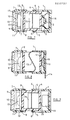
- the switch shown in Figure 6 comprises an elastomeric switch element 2 carrying a conductive rubber contact element 3.
- the switch element 2 bears on the actuator 4 and biases it outwardly of the housing 1.
- the actuator 4 deforms the switch element 2 so that the contact element 3 bridges contact tracks on the portion 16 of the flexible printed circuit board 14.
- the integrated circuit 13 is not provided with a cover in this arrangement.
- Figure 7 illustrates a modification of the switch of Figure 6 in which a plurality of light emitting diodes 17 are mounted on the circuit board 12 to provide back illumination for the liquid crystal display 10.
- the space between the circuit board 12 and the display 10 may be filled with a transparent or translucent epoxy resin to provide a desired visual effect.
- the epoxy resin is preferably the same type as is used in the manufacture of light emitting diodes and may be in any of the colours normally used, for instance water clear (colourless), transparent red, green or yellow, or translucent red, green or yellow, depending upon the colour of the illumination provided by the light emitting diodes 17.
- the switch element 2 is arranged to provide four millimeters of button travel and may be constructed so as to provide tactile feedback of when the switch has been actuated.
- the switch element 2 may be made of conductive silicone rubber so that the contact element 3 is unnecessary. In this case, the switch element acts directly to short together two tracks on the portion 16 of the flexible printed circuit board 14 when the switch is actuated.
- the switch element 2 may be made of non-conductive silicone rubber to provide four millimeters of button travel and may cooperate with a membrane switch formed by laminating the flexible printed circuit board at the portion 16 with a spacer and top contact layer.
- Figure 8 illustrates another type of switch assembly in which the element 2 is replaced by a metal click-dome 18 operated directly by the actuator 4 to provide between 0.3 and 0.5 millimeters of button travel with tactile feedback.
- the click-dome 18 is mounted directly on the portion 16 of the flexible printed circuit board 14 and, when actuated, shorts out adjacent tracks. This type of construction permits a low-profile switch assembly to be provided.
- a metal click-dome is provided but operates a membrane switch of the type described hereinbefore instead of acting as a switch contact itself.
- Figure 9 shows another switching arrangement employing a snap-action contact mechanism in the form of a microswitch 19 whose actuating element 20 rests directly against the actuator 4.
- a reed switch could be located in the housing 1 connected to the portion 16 of the flexible printed circuit board and a magnet fixed to the adjacent side of the actuator 4.
- solid state switching devices such as Hall-effect and capacitance switches may be used.
- the switching arrangement may also be provided separately from the pushbutton switch assembly and mounted directly on an equipment motherboard with the pushbutton switch mounted directly over it.
- the flexible printed circuit board which in this case does not carry the switching connections, may then be connected to the motherboard, for instance at some distance from the switch contacts by means of a suitable plug and socket arrangement.
- the pushbutton switch does not necessarily include the specific switch contact arrangement, which may be provided as a separate assembly.
- Switches of the type described hereinbefore are eminently suitable for use in an array or matrix and are well suited for inclusion in a standard keyboard array.
- Grouped switches may be assembled onto a common flexible printed circuit board to reduce the number of interconnections required, thus increasing the reliability and reducing cost.
- Such common printed circuit boards may also include address decoding to provide interfacing with an equipment motherboard. This is illustrated in Figure 10 of the accompanying drawings.
- switches 21 are connected by a bus 22 to an address decoder 23 which had a data input for receiving data to define the legends displayed by the switches, and a parallel four bit binary address input for selecting the switches.
- the bus 22 is also connected to circuitry (not shown) for providing a clock signal, power supplies V SS and V DD , and a voltage V LCD for powering the liquid crystal displays in the switches 21.
- Back light illumination signals may also be supplied to the switches 21.
- the decoder/driver integrated circuit 13 has on-board memory suitable for storing data defining the last legend or legends which were selected for display. Thus, new data need only be supplied when a new or modified legend is to be displayed.
- the switch contacts 24 may be polled in the usual way, for instance by a computer.
Landscapes
- Push-Button Switches (AREA)
Applications Claiming Priority (2)
| Application Number | Priority Date | Filing Date | Title |
|---|---|---|---|
| GB8602288 | 1986-01-30 | ||
| GB868602288A GB8602288D0 (en) | 1986-01-30 | 1986-01-30 | Relegendable pushbutton switches |
Publications (2)
| Publication Number | Publication Date |
|---|---|
| EP0232137A2 true EP0232137A2 (de) | 1987-08-12 |
| EP0232137A3 EP0232137A3 (de) | 1989-09-06 |
Family
ID=10592228
Family Applications (1)
| Application Number | Title | Priority Date | Filing Date |
|---|---|---|---|
| EP87300806A Withdrawn EP0232137A3 (de) | 1986-01-30 | 1987-01-29 | Drucktastenschalter mit veränderbarer Bezeichnung |
Country Status (2)
| Country | Link |
|---|---|
| EP (1) | EP0232137A3 (de) |
| GB (1) | GB8602288D0 (de) |
Cited By (22)
| Publication number | Priority date | Publication date | Assignee | Title |
|---|---|---|---|---|
| EP0329920A1 (de) * | 1988-02-23 | 1989-08-30 | TSCHUDIN & HEID AG | Tastschalter |
| GB2226454A (en) * | 1988-12-21 | 1990-06-27 | Ariel Pressings Ltd | Illuminated push button switches |
| FR2673761A1 (fr) * | 1991-03-08 | 1992-09-11 | Systemes Audio Frequences | Clavier a touches mobiles. |
| WO1994024683A1 (en) * | 1993-04-22 | 1994-10-27 | Maygay Machines Limited | Push-button switches |
| GB2310084A (en) * | 1996-02-12 | 1997-08-13 | Gamesman Ltd | Electrical switches |
| EP0751543A3 (de) * | 1995-06-27 | 1998-07-29 | Eaton Corporation | Schalteranordnung |
| WO1999059176A1 (de) * | 1998-05-09 | 1999-11-18 | Robert Bosch Gmbh | Taste für ein elektrisches gerät |
| EP1005055A3 (de) * | 1998-11-27 | 2001-11-07 | G&A Engineering S.r.l. | Leuchttastschalter mit elektronisch geregelte Farben und Helligkeit |
| WO2005029523A1 (de) * | 2003-09-12 | 2005-03-31 | Preh Gmbh | Bedienelement mit frei programmierbarer symbolik |
| EP1577916A1 (de) * | 2004-03-18 | 2005-09-21 | Valeo Schalter und Sensoren GmbH | Schaltereinheit für ein Kraftfahrzeug |
| WO2006056459A1 (de) * | 2004-11-25 | 2006-06-01 | Preh Gmbh | Bedienelement für ein kraftfahrzeug |
| US7485821B2 (en) | 2003-12-15 | 2009-02-03 | Preh Gmbh | Control element with animated symbols |
| WO2009000705A3 (de) * | 2007-06-22 | 2009-03-19 | Huf Huelsbeck & Fuerst Gmbh | Schaltvorrichtung |
| WO2009033468A1 (de) * | 2007-09-11 | 2009-03-19 | Osram Opto Semiconductors Gmbh | Anzeigeeinrichtung und tastenanordnung |
| US7628692B2 (en) | 2002-08-22 | 2009-12-08 | Igt | Gaming device having an input device with a display device |
| WO2011026118A1 (en) * | 2009-08-31 | 2011-03-03 | Advanced Input Devices, Inc. | Switch assembly |
| US8333657B1 (en) | 2011-09-26 | 2012-12-18 | Igt | Gaming system, gaming device and method for displaying multiple concurrent games using dynamic focal points |
| DE202012006899U1 (de) * | 2012-07-17 | 2013-10-18 | Alois Pöttinger Maschinenfabrik Ges.m.b.H. | Landwirtschaftliche Maschine |
| DE102013112953A1 (de) * | 2013-11-22 | 2015-05-28 | Ching-Hsiung Chu | Tastschalter mit Anzeige- und Wiedergabefunktion |
| DE102009010739B4 (de) * | 2008-02-27 | 2018-06-07 | Lg Electronics Inc. | Tastenanordnung und Waschmaschine mit dieser |
| US11333318B2 (en) * | 2020-02-07 | 2022-05-17 | Shandong University Of Science And Technology | Switch display apparatus and assembling method thereof |
| DE102023134924B3 (de) | 2023-12-13 | 2025-03-13 | Georg Schlegel Gmbh & Co. Kg | Druckstück für einen Betätiger einer elektrischen Schaltvorrichtung, Betätiger mit einem Druckstück sowie Schaltvorrichtung mit einem Betätiger |
Family Cites Families (5)
| Publication number | Priority date | Publication date | Assignee | Title |
|---|---|---|---|---|
| DE1193140B (de) * | 1963-06-14 | 1965-05-20 | Busch Jaeger Duerener Metall | Drucktastenschalter |
| US3467802A (en) * | 1968-06-21 | 1969-09-16 | Clare Pendar Co | Conductor apparatus for switch structure |
| DE8212658U1 (de) * | 1982-05-03 | 1982-08-19 | Teldix Gmbh, 6900 Heidelberg | Anzeige- und/oder Tastenfeldeinheit |
| JPS59164118U (ja) * | 1983-04-18 | 1984-11-02 | オムロン株式会社 | 照光式表示装置 |
| DE8334346U1 (de) * | 1983-11-30 | 1984-03-22 | Mueller, Rolf, Dr., 6750 Kaiserslautern | Vorrichtung, insbesondere fuer schreibmaschinen und terminals |
-
1986
- 1986-01-30 GB GB868602288A patent/GB8602288D0/en active Pending
-
1987
- 1987-01-29 EP EP87300806A patent/EP0232137A3/de not_active Withdrawn
Cited By (35)
| Publication number | Priority date | Publication date | Assignee | Title |
|---|---|---|---|---|
| EP0329920A1 (de) * | 1988-02-23 | 1989-08-30 | TSCHUDIN & HEID AG | Tastschalter |
| GB2226454A (en) * | 1988-12-21 | 1990-06-27 | Ariel Pressings Ltd | Illuminated push button switches |
| FR2673761A1 (fr) * | 1991-03-08 | 1992-09-11 | Systemes Audio Frequences | Clavier a touches mobiles. |
| WO1994024683A1 (en) * | 1993-04-22 | 1994-10-27 | Maygay Machines Limited | Push-button switches |
| EP0751543A3 (de) * | 1995-06-27 | 1998-07-29 | Eaton Corporation | Schalteranordnung |
| GB2310084A (en) * | 1996-02-12 | 1997-08-13 | Gamesman Ltd | Electrical switches |
| WO1999059176A1 (de) * | 1998-05-09 | 1999-11-18 | Robert Bosch Gmbh | Taste für ein elektrisches gerät |
| EP1005055A3 (de) * | 1998-11-27 | 2001-11-07 | G&A Engineering S.r.l. | Leuchttastschalter mit elektronisch geregelte Farben und Helligkeit |
| US7628692B2 (en) | 2002-08-22 | 2009-12-08 | Igt | Gaming device having an input device with a display device |
| WO2005029523A1 (de) * | 2003-09-12 | 2005-03-31 | Preh Gmbh | Bedienelement mit frei programmierbarer symbolik |
| JP2007505455A (ja) * | 2003-09-12 | 2007-03-08 | プレー・ゲゼルシャフト・ミト・ベシュレンクテル・ハフツング | 自由にプログラミング設定可能なシンボルを備えた操作エレメント |
| US7485821B2 (en) | 2003-12-15 | 2009-02-03 | Preh Gmbh | Control element with animated symbols |
| EP1577916A1 (de) * | 2004-03-18 | 2005-09-21 | Valeo Schalter und Sensoren GmbH | Schaltereinheit für ein Kraftfahrzeug |
| WO2006056459A1 (de) * | 2004-11-25 | 2006-06-01 | Preh Gmbh | Bedienelement für ein kraftfahrzeug |
| WO2009000705A3 (de) * | 2007-06-22 | 2009-03-19 | Huf Huelsbeck & Fuerst Gmbh | Schaltvorrichtung |
| US8446069B2 (en) | 2007-06-22 | 2013-05-21 | Huf Hulsbeck & Furst Gmbh & Co., Kg | Switch device |
| DE102007040604B4 (de) * | 2007-06-22 | 2018-11-08 | Huf Hülsbeck & Fürst Gmbh & Co. Kg | Schaltvorrichtung und Sicherheitssystem |
| WO2009033468A1 (de) * | 2007-09-11 | 2009-03-19 | Osram Opto Semiconductors Gmbh | Anzeigeeinrichtung und tastenanordnung |
| DE102009010739B4 (de) * | 2008-02-27 | 2018-06-07 | Lg Electronics Inc. | Tastenanordnung und Waschmaschine mit dieser |
| WO2011026118A1 (en) * | 2009-08-31 | 2011-03-03 | Advanced Input Devices, Inc. | Switch assembly |
| US8410383B2 (en) | 2009-08-31 | 2013-04-02 | Advanced Input Devices, Inc. | Switch display assembly with seal |
| US8932128B2 (en) | 2011-09-26 | 2015-01-13 | Igt | Gaming system, gaming device and method for displaying multiple concurrent games using dynamic focal points |
| US10152849B2 (en) | 2011-09-26 | 2018-12-11 | Igt | Gaming system, gaming device and method for displaying multiple concurrent games using dynamic focal points |
| US10825300B2 (en) | 2011-09-26 | 2020-11-03 | Igt | Gaming system, gaming device and method for displaying multiple concurrent games using dynamic focal points |
| US8333657B1 (en) | 2011-09-26 | 2012-12-18 | Igt | Gaming system, gaming device and method for displaying multiple concurrent games using dynamic focal points |
| US8622820B2 (en) | 2011-09-26 | 2014-01-07 | Igt | Gaming system, gaming device and method for displaying multiple concurrent games using dynamic focal points |
| US9286769B2 (en) | 2011-09-26 | 2016-03-15 | Igt | Gaming system, gaming device and method for displaying multiple concurrent games using dynamic focal points |
| US9600957B2 (en) | 2011-09-26 | 2017-03-21 | Igt | Gaming system, gaming device and method for displaying multiple concurrent games using dynamic focal points |
| US9905081B2 (en) | 2011-09-26 | 2018-02-27 | Igt | Gaming system, gaming device and method for displaying multiple concurrent games using dynamic focal points |
| FR2993431A1 (fr) * | 2012-07-17 | 2014-01-24 | Poettinger Alois Maschf | Machine agricole a systeme perfectionne d'affichage de parametres fonctionnels |
| DE202012006899U1 (de) * | 2012-07-17 | 2013-10-18 | Alois Pöttinger Maschinenfabrik Ges.m.b.H. | Landwirtschaftliche Maschine |
| DE102013112953B4 (de) * | 2013-11-22 | 2015-08-20 | Ching-Hsiung Chu | Tastschalter mit Anzeige- und Wiedergabefunktion |
| DE102013112953A1 (de) * | 2013-11-22 | 2015-05-28 | Ching-Hsiung Chu | Tastschalter mit Anzeige- und Wiedergabefunktion |
| US11333318B2 (en) * | 2020-02-07 | 2022-05-17 | Shandong University Of Science And Technology | Switch display apparatus and assembling method thereof |
| DE102023134924B3 (de) | 2023-12-13 | 2025-03-13 | Georg Schlegel Gmbh & Co. Kg | Druckstück für einen Betätiger einer elektrischen Schaltvorrichtung, Betätiger mit einem Druckstück sowie Schaltvorrichtung mit einem Betätiger |
Also Published As
| Publication number | Publication date |
|---|---|
| EP0232137A3 (de) | 1989-09-06 |
| GB8602288D0 (en) | 1986-03-05 |
Similar Documents
| Publication | Publication Date | Title |
|---|---|---|
| EP0232137A2 (de) | Drucktastenschalter mit veränderbarer Bezeichnung | |
| EP0203068B1 (de) | Verbesserungen der schalter und der tastaturen | |
| CN100350355C (zh) | 可修改的键区及其按钮机械装置 | |
| US4831359A (en) | Four quadrant touch pad | |
| US5134505A (en) | Push-button switch with liquid-crystal display | |
| US5278362A (en) | Push-button switch with display device | |
| US4163138A (en) | Flush lighted flat keyboard assembly | |
| US5151696A (en) | Multi-function keyboard for remote control apparatus | |
| US4231098A (en) | Casing of electronic calculators | |
| EP0134979A2 (de) | Elektrolumineszente Folientastatur | |
| US20050110762A1 (en) | Keyboard with changeable key display | |
| US4218603A (en) | Switching assembly equipped with display means installed behind the switching assembly | |
| GB2150722A (en) | Data entering device particularly for typewriters and terminals | |
| US4760218A (en) | Inter-locked button actuated matrix switch system, particularly for automotive instrumentation with button cluster switching | |
| US20060146027A1 (en) | Keypad and button mechanism having enhanced tactility | |
| GB2046996A (en) | Electrical switch | |
| US4501937A (en) | Integral multiswitch display panel | |
| US4796007A (en) | Micro-motion keyboard | |
| US4736190A (en) | Sheet membrane keyboard and electronic apparatus using same | |
| EP0697132B1 (de) | Tast schalter | |
| US7102086B2 (en) | Switch arrangement | |
| US4496812A (en) | Membrane panel | |
| US5160832A (en) | Front panel unit for electronic equipment | |
| US4181964A (en) | Integrated electronics assembly on a plastic chassis | |
| JP2876570B2 (ja) | キーボードスイッチ |
Legal Events
| Date | Code | Title | Description |
|---|---|---|---|
| PUAI | Public reference made under article 153(3) epc to a published international application that has entered the european phase |
Free format text: ORIGINAL CODE: 0009012 |
|
| AK | Designated contracting states |
Kind code of ref document: A2 Designated state(s): CH DE FR GB IT LI SE |
|
| PUAL | Search report despatched |
Free format text: ORIGINAL CODE: 0009013 |
|
| AK | Designated contracting states |
Kind code of ref document: A3 Designated state(s): CH DE FR GB IT LI SE |
|
| STAA | Information on the status of an ep patent application or granted ep patent |
Free format text: STATUS: THE APPLICATION IS DEEMED TO BE WITHDRAWN |
|
| 18D | Application deemed to be withdrawn |
Effective date: 19890801 |
|
| RIN1 | Information on inventor provided before grant (corrected) |
Inventor name: LITTLE, PHILIP VERNON Inventor name: BECKETT, NICHOLAS DAVID |