EP0231833B2 - Torblattglied - Google Patents
Torblattglied Download PDFInfo
- Publication number
- EP0231833B2 EP0231833B2 EP87100952A EP87100952A EP0231833B2 EP 0231833 B2 EP0231833 B2 EP 0231833B2 EP 87100952 A EP87100952 A EP 87100952A EP 87100952 A EP87100952 A EP 87100952A EP 0231833 B2 EP0231833 B2 EP 0231833B2
- Authority
- EP
- European Patent Office
- Prior art keywords
- door leaf
- edges
- reinforcing
- leaf member
- reinforcing struts
- Prior art date
- Legal status (The legal status is an assumption and is not a legal conclusion. Google has not performed a legal analysis and makes no representation as to the accuracy of the status listed.)
- Expired - Lifetime
Links
- 230000003014 reinforcing effect Effects 0.000 claims abstract description 54
- 239000000853 adhesive Substances 0.000 claims description 7
- 230000001070 adhesive effect Effects 0.000 claims description 7
- 239000012790 adhesive layer Substances 0.000 claims description 6
- 239000010410 layer Substances 0.000 claims 1
- 239000002184 metal Substances 0.000 abstract description 32
- 241000446313 Lamella Species 0.000 description 28
- 230000002787 reinforcement Effects 0.000 description 10
- 239000011324 bead Substances 0.000 description 5
- 238000003466 welding Methods 0.000 description 4
- 230000015572 biosynthetic process Effects 0.000 description 3
- 238000005253 cladding Methods 0.000 description 3
- JEIPFZHSYJVQDO-UHFFFAOYSA-N iron(III) oxide Inorganic materials O=[Fe]O[Fe]=O JEIPFZHSYJVQDO-UHFFFAOYSA-N 0.000 description 3
- 238000004519 manufacturing process Methods 0.000 description 3
- 239000011248 coating agent Substances 0.000 description 2
- 238000000576 coating method Methods 0.000 description 2
- 238000009413 insulation Methods 0.000 description 2
- 239000003973 paint Substances 0.000 description 2
- 238000004080 punching Methods 0.000 description 2
- 238000004381 surface treatment Methods 0.000 description 2
- 241000283707 Capra Species 0.000 description 1
- 230000006978 adaptation Effects 0.000 description 1
- 238000004026 adhesive bonding Methods 0.000 description 1
- 238000005452 bending Methods 0.000 description 1
- 238000010276 construction Methods 0.000 description 1
- 238000013016 damping Methods 0.000 description 1
- 238000006073 displacement reaction Methods 0.000 description 1
- 238000005516 engineering process Methods 0.000 description 1
- 230000007613 environmental effect Effects 0.000 description 1
- 238000000034 method Methods 0.000 description 1
- 210000002445 nipple Anatomy 0.000 description 1
- 230000007704 transition Effects 0.000 description 1
Images


Classifications
-
- E—FIXED CONSTRUCTIONS
- E06—DOORS, WINDOWS, SHUTTERS, OR ROLLER BLINDS IN GENERAL; LADDERS
- E06B—FIXED OR MOVABLE CLOSURES FOR OPENINGS IN BUILDINGS, VEHICLES, FENCES OR LIKE ENCLOSURES IN GENERAL, e.g. DOORS, WINDOWS, BLINDS, GATES
- E06B3/00—Window sashes, door leaves, or like elements for closing wall or like openings; Layout of fixed or moving closures, e.g. windows in wall or like openings; Features of rigidly-mounted outer frames relating to the mounting of wing frames
- E06B3/32—Arrangements of wings characterised by the manner of movement; Arrangements of movable wings in openings; Features of wings or frames relating solely to the manner of movement of the wing
- E06B3/48—Wings connected at their edges, e.g. foldable wings
- E06B3/485—Sectional doors
Definitions
- the invention relates to a door leaf member of a ceiling sectional door, a multi-part door leaf moved vertically or horizontally in its closed position or the like multi-part building closure with the features of the preamble of claim 1.
- Known lamellar door leaf members which are made of thin sheet metal, are welded together with lateral reinforcing struts running in the direction of movement of the door leaf and optionally also with one or more reinforcing struts arranged evenly distributed between them. This is usually done by spot welding or by a comparable welding process using welding nipples. This presupposes that the areas of the sheet metal lamella to be welded and the respective reinforcing strut are not electrically insulated from one another. If such insulation were already provided for the individual parts, for example in the form of a primer for the lamellar plate and / or the reinforcing strut profiles, then this would have to be removed.
- the invention has for its object to provide a door leaf member of the type mentioned, which is much easier and much more resistant to environmental influences and less noise.
- connection technology provided according to the invention between the sheet metal lamella and the reinforcing struts ensures that the parts brought together to form the dimensionally stable door leaf member, namely the sheet metal lamella on the one hand and the reinforcing struts on the other hand, are joined after the lamella sheet has been completely coated, stove-enamelled or otherwise finished with a surface treatment.
- the reinforcing struts can be provided with surface protection before being joined to the lamella sheet.
- the profile struts preferably consist of essentially U-shaped profiles which are cut to length. It is preferable to use galvanized sheets. As far as the cut edges remain unprotected, this has no more serious significance, because rust developing there does not impair the stability of the struts and does not appear to the outside.
- the reinforcing struts are thus glued to the sheet metal lamella of the door leaf member in the finished surface-treated state, specifically over a large area, so that a stable mounting is achieved.
- This gluing is limited to the inner surface of the sheet metal lamella lying in the level of the door leaf.
- the C-shaped bends that limit the sheet metal lamella perpendicular to the direction of the door leaf movement are not included in this bond. Due to the thin sheet used, the shape of this bend is low. For this reason, the reinforcing struts are positively connected with end sections projecting in their longitudinal direction to the edges of the bend lying in the door leaf plane, in such a way that an existing surface treatment, coating, application of paint or the like does not interfere with this either.
- the end sections of the reinforcing struts overlap in parallel the inside of the edges of the C-shaped bend and are connected to the edges in this area by the fact that on one of the adjacent parts perpendicular to the door movement direction, tab-like projections are provided, which are in one in the other Intervene in part of the opening provided and engage behind the edges which run approximately perpendicular to the direction of movement of the door.
- the play between the projections and the opening in the door leaf movement direction is kept small, so that the spacing of the edges of the upper and lower unwinding of the metal plate is fixed via the reinforcing struts.
- the reinforcing struts provided in the two edge regions of the sheet metal lamella extending in the direction of movement of the door leaf are provided with a cladding, which has the function of a reinforcing profile.
- This cladding is preferably pushed onto the door leaf member from the side, namely by clasping the respective lateral reinforcing strut and the edge region of the sheet metal laminate glued to it.
- the reinforcement profile overlaps the entire length of the respective edge region of the door leaf member and thus overlaps the end sections of the reinforcement strut and thus also the regions of the edges of the lower and upper C-shaped development of the sheet metal plate located there.
- An engagement flap is punched out in the overlap area in such a way that it turns after it has been turned protrudes into the opening in which the two projections already engage.
- the dimensioning is such that the width of the engaging flap punched out in the direction of movement of the door leaf has approximately the distance between the two projections engaging in the opening.
- the reinforcement profile is held almost free of play against lateral movements to the door movement direction and can therefore not be removed from its deferred position or the clasping.
- the screws additionally pass through correspondingly aligned bores in stops of threads which in this area articulate the successive door leaf members.
- the adhesive layer is preferably of a certain thickness.
- the adhesive itself is in particular permanently elastic, i.e. even after the "hardening" in a way resilient. This makes another special contribution to preventing noise.
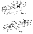
- the door leaf member 1 is formed from a sheet metal lamella 2, which on its longitudinal edges pointing in the direction of movement of the door leaf formed from a large number of such door leaf members 1 are provided with a C-shaped bend, which - FIGS. 2, 4 and 5 - initially from the inner surface 8 the sheet metal lamella 2, which lies in the door leaf level, is bent in steps at right angles and ends in an edge 6, which in turn runs parallel to the door leaf level.
- the edges 6 of the two bends 3 formed on the longitudinal edges 4 are directed towards one another with their free ends.
- This sheet metal lamella 2 is kept stiffened in the form described above with the aid of reinforcing struts 7.
- reinforcing struts 7 arranged on the edge regions 5 of the sheet metal lamella 2 running in the direction of movement of the door leaf are encompassed by reinforcing profiles 18, as will be explained in more detail in connection with FIG. 5.
- These reinforcing struts 18 cover the edge areas 5 in a box-like manner and reinforce the edge areas 5 of the door, on the bottom panel of which a rope of a weight compensation device acts on both sides.
- each reinforcing strut 7 consists of an essentially U-shaped profiled sheet, the legs 16 of which, in their free area, form bent edge webs 9, which describe a plane that describes runs parallel to the inside 8 of the sheet metal lamella 2.
- Adhesive layers 10 made of an adhesive are provided between the outer sides of the edge webs 9 of the reinforcing struts 7 facing this inner surface 8 and the adjoining area of the inner side 8, which adhesive also has permanently elastic properties after the setting, such that sound insulation in the transition area between the struts and the sheet metal lamella 2 is given or this is held on the struts 7 in a vibration-damped manner by the large-area strip-shaped adhesive layers 10.
- the sheet metal lamella 2 is provided in the area between its C-shaped bends 3 with beads 11 running parallel thereto, which run approximately perpendicular to the reinforcing struts 7 extending in the direction of movement of the door leaf. In the area of these beads, they face the inside 8 of the sheet metal lamella 2
- the ends of the legs 16 of the struts 7 are provided with cutouts 12, which encompass the bead 11 that passes through with a relatively large amount of play, so that no special requirements have to be made with regard to the manufacturing accuracy with regard to the adaptation between bead 11 and cutout 12.
- the edge webs 9 of the struts 7 are interrupted, as can be seen in FIG. 2.
- the adhesive layers 10 are limited to the edge webs 9, so that adhesive and non-contact gap zones are formed between the recesses and the beads.
- the dimension of the legs 16 to the web 17 of the U-shaped strut profile connecting them is such that the connecting web 17 with respect to its two end sections 13 provided on the front side on the surfaces of the edges 6 running parallel to the inside of the reinforcement profile 18 is present, as can be clearly seen in FIGS. 2, 4 and 5.
- a rectangular opening 15 is provided, which preferably extends further in the longitudinal direction of the longitudinal edges 4 and thus the edges 6 of the bends than perpendicular to it.
- a punching is provided corresponding to an opening 15, through which two tab-shaped projections 14 directed towards one another in the direction of the longitudinal edge are formed, each of which is bent around the adjacent, short edge of the opening 15 extending in the door leaf movement direction , for which express reference is made to FIG. 4, which clearly shows this clasping or reaching behind the narrow opening edges 15 through the projections 14 by a corresponding opening of a partial area of the contact zone between an end section 13 and an edge 6.
- the width of the projections 14 and the length of the short edges of the opening 15, around which the projections 14 are bent, are coordinated with one another in such a way that a displacement movement of the strut 7 with respect to the C-shaped bend is prevented at least approximately without play.
- the two C-shaped bends 3 in the two longitudinal edges 4 of the sheet metal lamella 2 are kept constant in shape via the struts 7 and form a transportable, stable, open-sided box construction. It is thus possible to transport and store a sheet metal lamella freshly glued to the struts and positively connected in the manner described above.
- the two struts 7 provided on the edge regions 5 running in the direction of movement of the door leaf are encompassed by a reinforcing profile 18, each of which, from the side, onto the strut and the wall zone of the sheet metal strip bonded thereto, holding these bonded parts between them, in the manner of clips is postponed.
- the reinforcement profile is held in this pushed-on position by punching out an engaging tab 20 projecting in the direction of movement of the door leaf in the region of its two front ends 19, in such a way positioned that the engaging tab in the shoulders of the bent projections 14 between the shoulders facing each other free space of the opening 15 in the associated edge 6 can be introduced by turning; this bent position is shown in dashed lines in Figure 5.
- the width of the engagement flap seen perpendicular to the door leaf movement direction is dimensioned such that the distance to the adjacent curvatures of the projections 14 is as small as possible. This ensures that the laterally pushed-on reinforcement profile is secured against slipping on the sheet metal lamella 2. Since the cladding reinforcement profile 18 is provided with embossments in the longitudinal direction of the edge regions 5 of the lamella 2 for reasons of stability, it is advisable to facilitate the ability of the engagement flap to be bent out of the profile plane by a bending zone opening 21 shown on the right in FIG. 5.
- the abutting areas of the bends 3 of the sheet metal lamella 2 - edge 6 -, the associated end sections 13 of the reinforcement profiles 7 and - in the case of the edge areas 5-end areas 19 of the reinforcement profiles 18 each have bores 22 provided, one each seen in the direction of the longitudinal edge 4 on both sides of the openings 15 or projections 14 and possibly the engaging flaps 20. In the contact area, these bores 22 are aligned with one another, so that two screw bolts can be inserted through the bores per connection point.
- the bolts pass through corresponding bores in a connecting tab of a hinge which bridges the two connecting areas in an articulated manner.
- the screw bolts pass through the bores 22 without a hinge flap being present.
- connection of the parts of the door leaf member is therefore designed in a variety of ways, first of all over a large area using a sound-absorbing adhesive, then by engaging protrusions or tabs in openings to stabilize the spatial shape and transportability of the individual door leaf member and finally immovably and in a known manner secured against breaking apart, when the door leaf members are assembled into a door leaf.
- the particular advantage of the formation of the door leaf member according to the invention lies in addition to its noise damping in that the individual parts can be safely surface-treated before assembly against weather influences such as rust formation and the like, without this disrupting the assembly.
- the sheet metal fins can already be provided with a stove enamelling, a coating or the like as a flat band and only then can they be deformed into the lamella profile. In addition to the rust-protected design of the door leaf member, this leads to a considerably simplified production.
Landscapes
- Engineering & Computer Science (AREA)
- Civil Engineering (AREA)
- Structural Engineering (AREA)
- Securing Of Glass Panes Or The Like (AREA)
- Glass Compositions (AREA)
- Laminated Bodies (AREA)
- Lock And Its Accessories (AREA)
- Junction Field-Effect Transistors (AREA)
- Control Of Stepping Motors (AREA)
- Building Environments (AREA)
- Polishing Bodies And Polishing Tools (AREA)
- Diaphragms For Electromechanical Transducers (AREA)
- Absorbent Articles And Supports Therefor (AREA)
- Gates (AREA)
- Casings For Electric Apparatus (AREA)
- Pinball Game Machines (AREA)
- Hinges (AREA)
Priority Applications (1)
| Application Number | Priority Date | Filing Date | Title |
|---|---|---|---|
| AT87100952T ATE58202T1 (de) | 1986-01-27 | 1987-01-23 | Torblattglied. |
Applications Claiming Priority (2)
| Application Number | Priority Date | Filing Date | Title |
|---|---|---|---|
| DE8601984U | 1986-01-27 | ||
| DE8601984U DE8601984U1 (de) | 1986-01-27 | 1986-01-27 | Torblattglied |
Publications (4)
| Publication Number | Publication Date |
|---|---|
| EP0231833A2 EP0231833A2 (de) | 1987-08-12 |
| EP0231833A3 EP0231833A3 (en) | 1987-12-23 |
| EP0231833B1 EP0231833B1 (de) | 1990-11-07 |
| EP0231833B2 true EP0231833B2 (de) | 1997-10-15 |
Family
ID=6790963
Family Applications (1)
| Application Number | Title | Priority Date | Filing Date |
|---|---|---|---|
| EP87100952A Expired - Lifetime EP0231833B2 (de) | 1986-01-27 | 1987-01-23 | Torblattglied |
Country Status (8)
| Country | Link |
|---|---|
| US (1) | US4794972A (da) |
| EP (1) | EP0231833B2 (da) |
| AT (1) | ATE58202T1 (da) |
| DE (2) | DE8601984U1 (da) |
| DK (1) | DK168996B1 (da) |
| ES (1) | ES2018790T5 (da) |
| GR (2) | GR3002555T3 (da) |
| NO (1) | NO166889C (da) |
Families Citing this family (13)
| Publication number | Priority date | Publication date | Assignee | Title |
|---|---|---|---|---|
| DE8800573U1 (de) * | 1988-01-19 | 1989-05-18 | Hörmann KG Brockhagen, 4803 Steinhagen | Torblattglied |
| US5060711A (en) * | 1988-11-10 | 1991-10-29 | Fimbell Iii Edward | Modular door panel structure and method of assembly and door assembled therefrom |
| DE4122981A1 (de) * | 1990-10-04 | 1992-04-09 | Erich Doering | Torblatt eines sektional- oder falttors, insbesondere fuer garagen oder hallen, mit aussteifungsprofilen |
| US6006817A (en) * | 1998-01-09 | 1999-12-28 | Clopay Building Products Company | Overhead door, panel and hinge assembly |
| US6772814B2 (en) | 1998-01-09 | 2004-08-10 | Clopay Building Products R&D Company, Inc. | Combined weather seal, light block and wear insert for overhead door panel |
| US6578619B2 (en) | 2001-05-21 | 2003-06-17 | Raynor Garage Doors | Overhead garage door |
| CA2383457A1 (en) * | 2002-04-25 | 2003-10-25 | Royal Group Technologies Limited | Modular garage door |
| AU2004228476A1 (en) * | 2003-04-11 | 2004-10-21 | The Provost, Fellows And Scholars Of The College Of The Holy And Undivided Trinity Of Queen Elizabeth Near Dublin | Use of HCV proteins |
| US8376021B2 (en) * | 2007-05-03 | 2013-02-19 | Hormann Kg Brockhagen | Component for producing a sectional door panel, shell for such a component, reinforcement strut for such a component, sectional door panel having such a component, and sectional door having a corresponding sectional door panel |
| WO2009015471A1 (en) * | 2007-07-27 | 2009-02-05 | Upwardor Corporation | Sectional doors made from polymer composites and a method for manufacturing same |
| CA2869625C (en) * | 2012-04-05 | 2016-02-23 | Nippon Sharyo, Ltd. | Rolling stock |
| JP6074155B2 (ja) * | 2012-04-23 | 2017-02-01 | 川崎重工業株式会社 | 鉄道車両用構体、及びそれを備える鉄道車両 |
| USD719280S1 (en) | 2013-03-07 | 2014-12-09 | Clopay Building Products Company, Inc. | Reinforcing strut for an overhead door |
Family Cites Families (7)
| Publication number | Priority date | Publication date | Assignee | Title |
|---|---|---|---|---|
| US1684966A (en) * | 1923-08-13 | 1928-09-18 | Simmons Co | Metal table |
| US2260590A (en) * | 1941-02-10 | 1941-10-28 | Tiffin Art Metal Company | Panel section |
| US2657645A (en) * | 1947-12-05 | 1953-11-03 | American Car & Foundry Co | Rail car panel |
| US2723731A (en) * | 1951-10-25 | 1955-11-15 | Air Maze Corp | Filter panel corner construction |
| AU426280B2 (en) * | 1968-05-15 | 1972-07-19 | Touma Door Company Pty. Limited | Sliding door |
| US4008745A (en) * | 1975-02-21 | 1977-02-22 | Overhead Door Corporation | Paneled door construction |
| US4367819A (en) * | 1980-07-30 | 1983-01-11 | Clip Strip Corporation | Display rack |
-
1986
- 1986-01-27 DE DE8601984U patent/DE8601984U1/de not_active Expired
-
1987
- 1987-01-23 DE DE8787100952T patent/DE3765945D1/de not_active Expired - Fee Related
- 1987-01-23 EP EP87100952A patent/EP0231833B2/de not_active Expired - Lifetime
- 1987-01-23 AT AT87100952T patent/ATE58202T1/de not_active IP Right Cessation
- 1987-01-23 ES ES87100952T patent/ES2018790T5/es not_active Expired - Lifetime
- 1987-01-26 DK DK040287A patent/DK168996B1/da not_active IP Right Cessation
- 1987-01-27 US US07/007,106 patent/US4794972A/en not_active Expired - Lifetime
- 1987-01-27 NO NO870317A patent/NO166889C/no unknown
-
1991
- 1991-01-30 GR GR90401119T patent/GR3002555T3/el unknown
-
1998
- 1998-01-12 GR GR980400040T patent/GR3026041T3/el unknown
Also Published As
| Publication number | Publication date |
|---|---|
| DE8601984U1 (de) | 1987-05-27 |
| EP0231833A2 (de) | 1987-08-12 |
| GR3002555T3 (en) | 1993-01-25 |
| DK40287A (da) | 1987-07-28 |
| DE3765945D1 (de) | 1990-12-13 |
| NO870317D0 (no) | 1987-01-27 |
| US4794972A (en) | 1989-01-03 |
| DK40287D0 (da) | 1987-01-26 |
| NO166889C (no) | 1991-09-11 |
| EP0231833B1 (de) | 1990-11-07 |
| GR3026041T3 (en) | 1998-04-30 |
| ATE58202T1 (de) | 1990-11-15 |
| ES2018790B3 (es) | 1991-05-16 |
| NO870317L (no) | 1987-07-28 |
| ES2018790T5 (es) | 1998-03-16 |
| DK168996B1 (da) | 1994-07-25 |
| EP0231833A3 (en) | 1987-12-23 |
| NO166889B (no) | 1991-06-03 |
Similar Documents
| Publication | Publication Date | Title |
|---|---|---|
| EP0231833B2 (de) | Torblattglied | |
| EP0087647A1 (de) | Kombinations-Eindeckrahmen für nebeneinander einzubauende Dachfenster | |
| DE3520500A1 (de) | Doppelwandiges blechelement | |
| DE2802151C3 (de) | Zum Errichten von Häusern, Garagen, Hallen u.dgl. dienende Wandtafel | |
| EP0196672A2 (de) | Paneele zur Verkleidung von Aussenwänden von Gebäuden | |
| WO2008135060A1 (de) | Bauelement zum herstellen eines sektionaltorblatts, schale für ein solches bauelement, verstärkungsstrebe für ein solches bauelement, sektionaltorblatt mit einem solchen bauelement und sektionaltor mit einem entsprechenden sektionaltorblatt | |
| DE3229814A1 (de) | Anordnung zum verbinden flaechenfoermiger elemente an benachbarten laengskanten | |
| EP1354545B1 (de) | Dichtung für eine Duschabtrennung | |
| DE4322631A1 (de) | Verbinder für C-Profile | |
| EP0647747B1 (de) | Tragwerk für die Bedachung und/oder Aussenhaut-Beplankung von Gebäuden | |
| DE4227311A1 (de) | Paneel für ein Decken- oder Seitensektionaltor | |
| EP0143150B1 (de) | Flanschverbindung | |
| EP4222325B1 (de) | Dichtungselement für eine bauwerksfuge | |
| DE2824396A1 (de) | Aus wenigstens zwei unterschiedlichen werkstoffen zusammengesetztes abdichtprofil | |
| DE19719671B4 (de) | Lamelle für ein Torblatt eines zwischen einer Offenstellung und einer Schließstellung bewegbaren Wandverschlusses | |
| DE19718449C2 (de) | Abschlußschiene aus zwei Schienenteilen für eine Bauwerks-Wärmedämmung oder eine Bauwerks-Schalldämmung | |
| DE8908704U1 (de) | Verbundelement für Bauzwecke | |
| EP0260421A2 (de) | Dämmplatte aus Hartschaum-Kunststoff | |
| DE19525206A1 (de) | Verglasungselemente | |
| DE1937443B2 (de) | Wand- und Deckenteile zur Bildung von Raeumen | |
| EP1574632B1 (de) | Trockenbauwand | |
| DE10217190A1 (de) | Profilplatte zum Eindecken eines Gebäudedachs sowie Gebäudedach | |
| DE2114939A1 (de) | Fenster | |
| DE4336077A1 (de) | Trennwand in Trockenbauweise | |
| DE2243021C3 (de) | Befestigung einer feststehenden Zarge für Türen oder Fenster an Tragschienen |
Legal Events
| Date | Code | Title | Description |
|---|---|---|---|
| PUAI | Public reference made under article 153(3) epc to a published international application that has entered the european phase |
Free format text: ORIGINAL CODE: 0009012 |
|
| AK | Designated contracting states |
Kind code of ref document: A2 Designated state(s): AT BE CH DE ES FR GB GR IT LI LU NL SE |
|
| PUAL | Search report despatched |
Free format text: ORIGINAL CODE: 0009013 |
|
| AK | Designated contracting states |
Kind code of ref document: A3 Designated state(s): AT BE CH DE ES FR GB GR IT LI LU NL SE |
|
| 17P | Request for examination filed |
Effective date: 19880620 |
|
| 17Q | First examination report despatched |
Effective date: 19890623 |
|
| GRAA | (expected) grant |
Free format text: ORIGINAL CODE: 0009210 |
|
| AK | Designated contracting states |
Kind code of ref document: B1 Designated state(s): AT BE CH DE ES FR GB GR IT LI LU NL SE |
|
| REF | Corresponds to: |
Ref document number: 58202 Country of ref document: AT Date of ref document: 19901115 Kind code of ref document: T |
|
| REF | Corresponds to: |
Ref document number: 3765945 Country of ref document: DE Date of ref document: 19901213 |
|
| ET | Fr: translation filed | ||
| ITF | It: translation for a ep patent filed | ||
| GBT | Gb: translation of ep patent filed (gb section 77(6)(a)/1977) | ||
| PLBI | Opposition filed |
Free format text: ORIGINAL CODE: 0009260 |
|
| 26 | Opposition filed |
Opponent name: HOESCH AG, Effective date: 19910807 |
|
| NLR1 | Nl: opposition has been filed with the epo |
Opponent name: HOESCH AG. |
|
| ITTA | It: last paid annual fee | ||
| REG | Reference to a national code |
Ref country code: GR Ref legal event code: FG4A Free format text: 3002555 |
|
| PLAB | Opposition data, opponent's data or that of the opponent's representative modified |
Free format text: ORIGINAL CODE: 0009299OPPO |
|
| R26 | Opposition filed (corrected) |
Opponent name: FRIED. KRUPP AG HOESCH-KRUPP Effective date: 19910807 |
|
| PLAB | Opposition data, opponent's data or that of the opponent's representative modified |
Free format text: ORIGINAL CODE: 0009299OPPO |
|
| NLXE | Nl: other communications concerning ep-patents (part 3 heading xe) |
Free format text: PAT.BUL.23/91 CORR.:FRIED. KRUPP AG HOESCH-KRUPP |
|
| R26 | Opposition filed (corrected) |
Opponent name: FRIED. KRUPP AG HOESCH-KRUPP Effective date: 19910807 |
|
| EPTA | Lu: last paid annual fee | ||
| EAL | Se: european patent in force in sweden |
Ref document number: 87100952.8 |
|
| PLBQ | Unpublished change to opponent data |
Free format text: ORIGINAL CODE: EPIDOS OPPO |
|
| PLAB | Opposition data, opponent's data or that of the opponent's representative modified |
Free format text: ORIGINAL CODE: 0009299OPPO |
|
| APAC | Appeal dossier modified |
Free format text: ORIGINAL CODE: EPIDOS NOAPO |
|
| PLAW | Interlocutory decision in opposition |
Free format text: ORIGINAL CODE: EPIDOS IDOP |
|
| R26 | Opposition filed (corrected) |
Opponent name: FRIED. KRUPP AG HOESCH-KRUPP Effective date: 19910807 |
|
| NLR1 | Nl: opposition has been filed with the epo |
Opponent name: FRIED. KRUPP AG HOESCH-KRUPP |
|
| PLAW | Interlocutory decision in opposition |
Free format text: ORIGINAL CODE: EPIDOS IDOP |
|
| PUAH | Patent maintained in amended form |
Free format text: ORIGINAL CODE: 0009272 |
|
| STAA | Information on the status of an ep patent application or granted ep patent |
Free format text: STATUS: PATENT MAINTAINED AS AMENDED |
|
| 27A | Patent maintained in amended form |
Effective date: 19971015 |
|
| AK | Designated contracting states |
Kind code of ref document: B2 Designated state(s): AT BE CH DE ES FR GB GR IT LI LU NL SE |
|
| REG | Reference to a national code |
Ref country code: CH Ref legal event code: AEN Free format text: AUFRECHTERHALTUNG DES PATENTES IN GEAENDERTER FORM |
|
| NLR2 | Nl: decision of opposition | ||
| ITF | It: translation for a ep patent filed | ||
| PG25 | Lapsed in a contracting state [announced via postgrant information from national office to epo] |
Ref country code: GR Free format text: THE PATENT HAS BEEN ANNULLED BY A DECISION OF A NATIONAL AUTHORITY Effective date: 19980112 |
|
| ET3 | Fr: translation filed ** decision concerning opposition | ||
| GBTA | Gb: translation of amended ep patent filed (gb section 77(6)(b)/1977) | ||
| NLR3 | Nl: receipt of modified translations in the netherlands language after an opposition procedure | ||
| REG | Reference to a national code |
Ref country code: ES Ref legal event code: DC2A Kind code of ref document: T5 Effective date: 19980115 |
|
| REG | Reference to a national code |
Ref country code: GB Ref legal event code: IF02 |
|
| PGFP | Annual fee paid to national office [announced via postgrant information from national office to epo] |
Ref country code: CH Payment date: 20041229 Year of fee payment: 19 |
|
| PGFP | Annual fee paid to national office [announced via postgrant information from national office to epo] |
Ref country code: FR Payment date: 20041230 Year of fee payment: 19 Ref country code: AT Payment date: 20041230 Year of fee payment: 19 |
|
| PGFP | Annual fee paid to national office [announced via postgrant information from national office to epo] |
Ref country code: GB Payment date: 20050113 Year of fee payment: 19 |
|
| PGFP | Annual fee paid to national office [announced via postgrant information from national office to epo] |
Ref country code: SE Payment date: 20050114 Year of fee payment: 19 |
|
| PGFP | Annual fee paid to national office [announced via postgrant information from national office to epo] |
Ref country code: LU Payment date: 20050124 Year of fee payment: 19 |
|
| PGFP | Annual fee paid to national office [announced via postgrant information from national office to epo] |
Ref country code: ES Payment date: 20050125 Year of fee payment: 19 |
|
| PGFP | Annual fee paid to national office [announced via postgrant information from national office to epo] |
Ref country code: NL Payment date: 20050128 Year of fee payment: 19 Ref country code: GR Payment date: 20050128 Year of fee payment: 19 |
|
| PGFP | Annual fee paid to national office [announced via postgrant information from national office to epo] |
Ref country code: BE Payment date: 20050131 Year of fee payment: 19 |
|
| PGFP | Annual fee paid to national office [announced via postgrant information from national office to epo] |
Ref country code: DE Payment date: 20050222 Year of fee payment: 19 |
|
| APAH | Appeal reference modified |
Free format text: ORIGINAL CODE: EPIDOSCREFNO |
|
| PG25 | Lapsed in a contracting state [announced via postgrant information from national office to epo] |
Ref country code: GB Free format text: LAPSE BECAUSE OF NON-PAYMENT OF DUE FEES Effective date: 20060123 Ref country code: AT Free format text: LAPSE BECAUSE OF NON-PAYMENT OF DUE FEES Effective date: 20060123 |
|
| PG25 | Lapsed in a contracting state [announced via postgrant information from national office to epo] |
Ref country code: SE Free format text: LAPSE BECAUSE OF NON-PAYMENT OF DUE FEES Effective date: 20060124 Ref country code: ES Free format text: LAPSE BECAUSE OF NON-PAYMENT OF DUE FEES Effective date: 20060124 |
|
| PG25 | Lapsed in a contracting state [announced via postgrant information from national office to epo] |
Ref country code: LU Free format text: LAPSE BECAUSE OF NON-PAYMENT OF DUE FEES Effective date: 20060131 Ref country code: LI Free format text: LAPSE BECAUSE OF NON-PAYMENT OF DUE FEES Effective date: 20060131 Ref country code: FR Free format text: LAPSE BECAUSE OF NON-PAYMENT OF DUE FEES Effective date: 20060131 Ref country code: CH Free format text: LAPSE BECAUSE OF NON-PAYMENT OF DUE FEES Effective date: 20060131 Ref country code: BE Free format text: LAPSE BECAUSE OF NON-PAYMENT OF DUE FEES Effective date: 20060131 |
|
| PGFP | Annual fee paid to national office [announced via postgrant information from national office to epo] |
Ref country code: IT Payment date: 20060131 Year of fee payment: 20 |
|
| PG25 | Lapsed in a contracting state [announced via postgrant information from national office to epo] |
Ref country code: NL Free format text: LAPSE BECAUSE OF NON-PAYMENT OF DUE FEES Effective date: 20060801 Ref country code: DE Free format text: LAPSE BECAUSE OF NON-PAYMENT OF DUE FEES Effective date: 20060801 |
|
| REG | Reference to a national code |
Ref country code: CH Ref legal event code: PL |
|
| EUG | Se: european patent has lapsed | ||
| GBPC | Gb: european patent ceased through non-payment of renewal fee |
Effective date: 20060123 |
|
| NLV4 | Nl: lapsed or anulled due to non-payment of the annual fee |
Effective date: 20060801 |
|
| REG | Reference to a national code |
Ref country code: FR Ref legal event code: ST Effective date: 20060929 |
|
| REG | Reference to a national code |
Ref country code: ES Ref legal event code: FD2A Effective date: 20060124 |
|
| BERE | Be: lapsed |
Owner name: *HORMANN K.G. BROCKHAGEN Effective date: 20060131 |