EP0230764A2 - Palettenspannvorrichtung - Google Patents
Palettenspannvorrichtung Download PDFInfo
- Publication number
- EP0230764A2 EP0230764A2 EP86309934A EP86309934A EP0230764A2 EP 0230764 A2 EP0230764 A2 EP 0230764A2 EP 86309934 A EP86309934 A EP 86309934A EP 86309934 A EP86309934 A EP 86309934A EP 0230764 A2 EP0230764 A2 EP 0230764A2
- Authority
- EP
- European Patent Office
- Prior art keywords
- pallet
- clamping
- manual operation
- operation lever
- positioning
- Prior art date
- Legal status (The legal status is an assumption and is not a legal conclusion. Google has not performed a legal analysis and makes no representation as to the accuracy of the status listed.)
- Granted
Links
Images
Classifications
-
- B—PERFORMING OPERATIONS; TRANSPORTING
- B23—MACHINE TOOLS; METAL-WORKING NOT OTHERWISE PROVIDED FOR
- B23Q—DETAILS, COMPONENTS, OR ACCESSORIES FOR MACHINE TOOLS, e.g. ARRANGEMENTS FOR COPYING OR CONTROLLING; MACHINE TOOLS IN GENERAL CHARACTERISED BY THE CONSTRUCTION OF PARTICULAR DETAILS OR COMPONENTS; COMBINATIONS OR ASSOCIATIONS OF METAL-WORKING MACHINES, NOT DIRECTED TO A PARTICULAR RESULT
- B23Q1/00—Members which are comprised in the general build-up of a form of machine, particularly relatively large fixed members
- B23Q1/25—Movable or adjustable work or tool supports
- B23Q1/26—Movable or adjustable work or tool supports characterised by constructional features relating to the co-operation of relatively movable members; Means for preventing relative movement of such members
- B23Q1/28—Means for securing sliding members in any desired position
-
- B—PERFORMING OPERATIONS; TRANSPORTING
- B23—MACHINE TOOLS; METAL-WORKING NOT OTHERWISE PROVIDED FOR
- B23Q—DETAILS, COMPONENTS, OR ACCESSORIES FOR MACHINE TOOLS, e.g. ARRANGEMENTS FOR COPYING OR CONTROLLING; MACHINE TOOLS IN GENERAL CHARACTERISED BY THE CONSTRUCTION OF PARTICULAR DETAILS OR COMPONENTS; COMBINATIONS OR ASSOCIATIONS OF METAL-WORKING MACHINES, NOT DIRECTED TO A PARTICULAR RESULT
- B23Q16/00—Equipment for precise positioning of tool or work into particular locations not otherwise provided for
- B23Q16/02—Indexing equipment
- B23Q16/04—Indexing equipment having intermediate members, e.g. pawls, for locking the relatively movable parts in the indexed position
Definitions
- the present invention relates to a pallet-clamping device used for a machine tool such as a machining center. More particularly, the present invention relates to a pallet-clamping device for manually carrying out the operations of positioning and clamping a work pallet to a work table of a machine tool.
- a pallet-clamping device for positioning and fixing a work pallet to the work table has been recently used together with a pallet-changing device for changing a work pallet on the pallet-clamping device.
- An ordinary pallet-clamping device comprises a base block secured to a work table of a machining center or the like, a positioning unit for positioning a work pallet relative to the base block, and a clamping unit for clamping the work pallet to the base block, and these positioning and clamping units are automatically operated by an actuator driven by a drive source such as a hydraulic pressure, pneumatic pressure, or electric power.
- this automatic pallet-clamping device a work pallet delivered onto the pallet-clamping device can be automatically positioned and fixed, and therefore, this automatic pallet-clamping device can carry out a very efficient exchange of work pallets between the pallet-changing device and the machining center or the like.
- This type of pallet-clamping device is expensive, and is disadvantageous in that careful maintenance is necessary.
- the pallet-clamping device is attached to the already existing machining center or the like, complicated wiring work must be carried out and thus the cost is increased.
- a hydraulic pressure-generating device, a pneumatic pressure-generating device or the like must be provided, it is often difficult to later install such a device in a relatively small-sized factory.
- a method may be considered in which the respective units of the pallet-clamping device are manually operated.
- the operation becomes complicated and a failure to perform a certain operation can result in an accident.
- a work pallet is manually delivered onto the pallet-clamping device, if the delivery force is too strong, a return or rebound of the work pallet occurs and the subsequent clamping operation or positioning operaion often becomes difficult.
- Another object of the present invention is to provide a manual type pallet-clamping device in which the operations of positioning and clamping a work pallet to a work table of a machine tool can be efficiently performed and a rebound of the work pallet can be completely prevented.
- a pallet-clamping device comprising, a base block secured to a work table of a machine tool, a positioning unit for positioning a work pallet for holding a work piece relative to the base block, a clamping unit for clamping the work pallet to the base block, a manual operation lever movable between predetermined first and second positions, and an operating unit for simultaneously operating the positioning unit and the clamping unit in accordance with the movement of the manual operation lever between the first and second positions.
- a pallet-clamping device comprising, a base block secured to a work table of a machine tool, a positioning unit for positioning a work pallet for holding a work piece relative to the base block, a clamping unit for clamping the work pallet to the base block, a latch unit engaged with the work pallet to prevent a rebound of the work pallet when the work pallet is supplied onto the base block along the top face of the clamping unit, a manual operation lever movable between predetermined first annd second positions, and an operating unit for simultaneously operating the positioning unit and the clamping unit in accordance with the movement of the manual operation lever between the first and second positions, and for separating the latch unit from the work pallet when said manual operation lever moves between the first and second positions.
- the structure is simplified, and the pallet-clamping device can be easily attached later to an existing machine tool such as a machining center. Furthermore, since the positioning unit and clamping unit can be simultaneously operated by the manual operation lever, and the operations of these units can be simultaneously released, the clamping device can be simply handled and failure to perform the operation of the positioning unit or clamping unit can be prevented.
- the latch unit when a work pallet is manually delivered onto the pallet-clamping device, the latch unit is automatically operated mechanically to prevent a rebound of the work pallet, and therefore, the subsequent clamping or positioning operation can be performed conveniently and safely. Moreover, when the positioning unit and clamping unit are operated by the manual operation lever, the latch unit can be separated, and therefore, the operation of separating the latch unit need not be independently performed and the entire operation is further simplified.
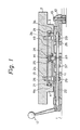
- Figures l through 4 show one embodiment of the pallet-clamping device according to the present invention.
- the manual type pallet-clamping device has a base block ll secured to a work table l of a work tool such as a machining center.
- the base block ll is secured to a desired position on the work table l by a stopper l2 and a clamping bolt l3.
- the pallet-clamping device comprises a clamping unit l4 for clamping a work pallet 2 to the base block ll, a positioning unit l5 for positioning the work pallet 2 relative to the base block ll, a latch unit l6 for preventing a rebound of the work pallet 2, and a manual operation lever l7.
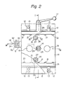
- the clamping unit l4 includes a clamp plate l8 slidably mounted on the base block ll. As shown in Figs. 2 and 3, a pair of guide poles l9 extending downward are secured to the clamp plate l8, and the guide poles l9 are slidably fitted in a pair of guide holes 20 formed in the base block ll, respectively.
- a plurality of rollers 2l are arranged on the clamp plate l8 in two rows along the direction in which the work pallet 2 is supplied. As seen from Fig. l, the top faces of the rollers 2l are located above the top face of the clamp plate l8, and the bottom faces of the rollers 2l are located above the lower face of the clamp plate l8.
- a pair of legs 3 and 4 are arranged on the lower face of the work pallet 2.
- the legs 3 and 4 extend downward below the work pallet 2 and along the direction in which the work pallet 2 is supplied.
- Ribs 3a and 4a extending inward are formed on the lower ends of the legs 3 and 4.
- the clamp plate l8 can move in the vertical direction relative to the base block ll. When the clamp plate l8 moves upward, the clamping unit l4 is in the unclamping state. In this state, the rollers 2l abut against the lower face of the supplied work pallet 2 to support the work pallet 2.
- the lower face of the clamp plate l8 is separate from and is located above the ribs 3a and 4a of the work pallet 2, and the lower faces of the ribs 3a and 4a are separate from the upper face of the base block ll and located above the base block ll. Accordingly, the supplied work pallet 2 is smoothly guided by the rollers 2l.
- the clamp plate l8 moves downward, the clamping unit l4 is in the clamping state, and the ribs 3a and 4a of the work pallet 2 are clamped by the lower face of the clamp plate l8 and the upper face of the base block ll. In this state, the rollers 2l are separate from the lower face of the work pallet 2.
- An operation shaft 22 extending in the direction orthogonal to the direction in which the work pallet 2 is supplied is rotatably supported on the base block ll, and a manual operation lever l7 is fixed to one end of the operation shaft 22.
- a manual operation lever l7 is fixed to one end of the operation shaft 22.
- an eccentric cam 23 is secured to the operation shaft 22, and a link lever 24 fitted with the eccentric cam 23 is pivoted on the clamp plate l8 by a pivoting pin 25.
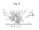
- the positioning unit l5 has a pair of positioning pins 26, and these positioning pins 26 are slidably fitted in a pair of boss portions 27 formed on the base block ll, respectively, and the boss portions 27 are freely fitted in a pair of holes 28 formed in the clamp plate l8, respectively.
- a pair of positioning holes 2a, into which the positioning pins 26 can fit, respectively, are formed in the work pallet 2, and by engagement of the pins 26 with the holes 2a, the work pallet 2 is positioned relative to the base block ll.
- a pair of cams 29 are arranged on the operation shaft 22 to move the positioning pins 26 in the vertical direction.
- Figure 4 shows in detail an engagement structure of one of the cams 29 with the operating shaft 22 and with the corresponding positioning pin 26.
- the cam 29 has a claw 30 to be engaged with a notch 26a of the positioning pin 26.
- the cam 29 is rotatably fitted to the operation shaft 29.
- a slit 29a extending in the circumferential direction is formed in the cam 29, and a pin 3l to be located within the slit 29a is mounted on the operation shaft 22.
- the positioning pin 26 is fitted in the positioning hole 2a of the work pallet 2, and the manual operation lever l7 is located at the position indicated by A in Fig. 4. At this time, the clamping unit l4 is in the clamping state. If the manual operation lever l7 is turned counterclockwise in the drawings, the operation shaft 22 is rotated counterclockwise together with the manual operation lever l7 and the pin 3l is moved within the slit 29a. The cam 29 is kept stationary and, hence, the positioning pin 26 is also kept stationary, at the position indicated in the drawings. When the manual operation lever l7 is turned further, the cam 29 receives the action of the pin 3l and is rotated counterclockwise to push down the positioning pin 26. When the manual operation lever l7 is located at the position indicated by B in the drawings, the clamping unit l4 is in the unclamping state, and the positioning pin 26 is separate from the positioning hole 2a of the work pallet 2.
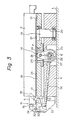
- the latch unit l6 has a movable hook 32, and this movable hook 32 is rotatably supported through a pivoting pin 34 on a bracket 33 mounted on the base block ll.
- the movable hook 32 has a stopper 35, and this stopper 35 can abut against a stationary hook 5 mounted on the end of the work pallet 2.
- the position of the movable hook 32 can be changed between a latching position for engagement with the stationary hook 5 of the work pallet 2 (position C in Fig. 3) and an unlatching position for separation from the stationary hook 5 (position D in Fig. 3).
- Two dents 32a and 32b are formed on the side face of the movable hook 32.
- a ball (not shown in the drawings) that can be engaged with the dent 32a or 32b is held on the bracket 33 and urged toward the side face of the movable hook 32 by a spring, so that the movable hook 32 is held at the latching position C or the unlatching position D by engagement of the ball with the dent 32a or 32b of the movable hook 32.
- the movable hook 32 When the movable hook 32 is located at the unlatching position D, if the stationary hook 5 of the work pallet 2 supplied onto the pallet-clamping device pushes the stopper 35 of the movable hook 32, the movable hook 32 is turned around the pivoting pin 34 and is changed to the latching position D, whereby a return of the work pallet 2, that is, a rebound of the work pallet 2, can be prevented.
- a push rod 36 is slidably mounted on the base block ll in the longitudinal direction so that the push rod 36 can abut against the movable hook 32.
- An operation cam 37 that can abut against the push rod 36 is mounted on the operation shaft 22.
- the operation cam 37 is located at the position E shown in Fig. 3. If the manual operation lever l7 is shifted from the unclamping position B to the clamping position A, the operation cam 37 is moved from the position E to the position F. During this movement, the movable hook 32 located at the latching position C is pressed through the push rod 36 and the position of the movable hook 32 is changed from the latching position C to the unlatching position D.
- the movable hook 32 becomes engaged with the stationary hook 5 to prevent rebound of the work pallet 2. If the manual operation lever l7 is then shifted to the clamping position A from the unclamping position B, the positioning pins 26 are fitted in the positioning holes 2a of the work pallet 2 to locate the work pallet 2 at a predetermined position.
- the clamp plate l8 is caused to press the work pallet 2 onto the base block ll and clamp the work pallet 2, and by the action of the operation cam 37 and push rod 36, the movable hook 32 is returned to the unlatching position D from the latching position C.
- the manual operation lever l7 is shifted to the unclamping position B from the clamping position A, whereby the clamping unit l4 is changed from the clamping state to the unclamping state and the positioning pins 26 of the positioning unit l5 are separated from the positioning holes 2a of the work pallet 2. Since the movable hook 32 of the latch unit l6 has been separated from the stationary hook 5 of the work pallet 2 at this point, after the manual operation lever l7 is shifted to the unclamping position B, the work pallet 2 can be immediately taken out from the pallet-clamping device.
Landscapes
- Engineering & Computer Science (AREA)
- Mechanical Engineering (AREA)
- Feeding Of Workpieces (AREA)
- Jigs For Machine Tools (AREA)
Applications Claiming Priority (2)
| Application Number | Priority Date | Filing Date | Title |
|---|---|---|---|
| JP293283/85 | 1985-12-27 | ||
| JP60293283A JPS62157754A (ja) | 1985-12-27 | 1985-12-27 | パレツトクランプ装置 |
Publications (3)
| Publication Number | Publication Date |
|---|---|
| EP0230764A2 true EP0230764A2 (de) | 1987-08-05 |
| EP0230764A3 EP0230764A3 (en) | 1988-11-23 |
| EP0230764B1 EP0230764B1 (de) | 1992-09-30 |
Family
ID=17792824
Family Applications (1)
| Application Number | Title | Priority Date | Filing Date |
|---|---|---|---|
| EP86309934A Expired EP0230764B1 (de) | 1985-12-27 | 1986-12-18 | Palettenspannvorrichtung |
Country Status (4)
| Country | Link |
|---|---|
| US (1) | US4738439A (de) |
| EP (1) | EP0230764B1 (de) |
| JP (1) | JPS62157754A (de) |
| DE (1) | DE3686877T2 (de) |
Cited By (3)
| Publication number | Priority date | Publication date | Assignee | Title |
|---|---|---|---|---|
| FR2613969A1 (fr) * | 1987-04-16 | 1988-10-21 | Schwaebische Huettenwerke Gmbh | Dispositif de changement de palettes comportant une table de maintien |
| EP0645213A1 (de) * | 1993-09-24 | 1995-03-29 | DECKEL MAHO GmbH | Vorrichtung zur lagefixierten Positionierung einer Palette auf einem Augspanntisch |
| EP1053846A3 (de) * | 1999-05-17 | 2004-01-21 | HILTI Aktiengesellschaft | Säge mit mittels Schnellverschluss verbindbaren Sägekopf und Sägeschlitten |
Families Citing this family (13)
| Publication number | Priority date | Publication date | Assignee | Title |
|---|---|---|---|---|
| US4881727A (en) * | 1987-08-06 | 1989-11-21 | Joseph Deutsch | Clamping mechanism |
| DE4005052A1 (de) * | 1989-02-17 | 1990-09-13 | Yamazaki Mazak Corp | Aufspannvorrichtung fuer werkstuecke und spannvorrichtung fuer dieselbe |
| US5044616A (en) * | 1989-11-21 | 1991-09-03 | Jakob Tooling, Inc. | Locating device for workpiece-processing apparatus |
| US5167405A (en) * | 1991-08-21 | 1992-12-01 | Midaco Corporation | Fast change set-up device for work on work support |
| US5286148A (en) * | 1993-03-15 | 1994-02-15 | Midaco Corporation | Table extender for a milling machine |
| JPH08118175A (ja) * | 1994-10-21 | 1996-05-14 | Imao Corp:Kk | 取付用ベース部材及びそのベース部材に取り付けられる取付具 |
| IT1314336B1 (it) * | 1999-12-29 | 2002-12-09 | Omba S R L | Paletta per il bloccaggio di un pezzo da sottoporre a lavorazioni |
| DE102005056449A1 (de) * | 2005-11-26 | 2007-08-02 | Alfing Kessler Sondermaschinen Gmbh | Werkstückhaltevorrichtung und damit ausgestattete Bearbeitungsmaschine |
| US7975998B2 (en) * | 2006-04-03 | 2011-07-12 | Midaco Corporation | Pallet changer and system and method for using the same |
| CN104070370B (zh) * | 2013-03-25 | 2016-08-03 | 富泰华工业(深圳)有限公司 | 装夹装置 |
| US20170326702A1 (en) * | 2016-05-12 | 2017-11-16 | Tsudakoma Kogyo Kabushiki Kaisha | Rotary table device for machine tool |
| US10871507B2 (en) * | 2018-12-20 | 2020-12-22 | Texas Instruments Incorporated | Semiconductor device handler with chuck clamp interlock |
| CN117465973B (zh) * | 2023-12-27 | 2024-03-15 | 常州长盛机械有限公司 | 挖掘机用金属横梁切割成型用输送设备 |
Family Cites Families (9)
| Publication number | Priority date | Publication date | Assignee | Title |
|---|---|---|---|---|
| DE882828C (de) * | 1944-02-01 | 1953-07-13 | Luebecker Maschb Ag | Feststellvorrichtung fuer fahrbare Spannvorrichtungen einer Fertigungsstrasse |
| US2672675A (en) * | 1950-02-04 | 1954-03-23 | Ralph E Cross | Locating and clamping mechanism |
| NL269918A (de) * | 1960-10-04 | |||
| JPS5438633U (de) * | 1977-08-15 | 1979-03-14 | ||
| US4201284A (en) * | 1978-11-02 | 1980-05-06 | Brems John Henry | Pallet registry system |
| JPS605417B2 (ja) * | 1981-01-30 | 1985-02-12 | 本田技研工業株式会社 | 工作機械における治具台装置 |
| JPS5822232U (ja) * | 1981-08-04 | 1983-02-10 | 相生精機株式会社 | 工作機械へのクランプパレツト交換装置 |
| IT8254037U1 (it) * | 1982-12-07 | 1984-06-07 | Comau Spa | Dispositivo di riferimento e bloccaggio di un attrezzatura portapezzo in lavorazione sull'attrezzo fisso di una macchina utensile. |
| SE440618B (sv) * | 1983-04-12 | 1985-08-12 | Schedwin Sven Erik | Fastspenningsanordning, i synnerhet for fastspenning av arbetsbord, fixturer eller liknande pa ett underlag, sasom maskinbordet i en bearbetningsmaskin |
-
1985
- 1985-12-27 JP JP60293283A patent/JPS62157754A/ja active Granted
-
1986
- 1986-12-18 EP EP86309934A patent/EP0230764B1/de not_active Expired
- 1986-12-18 DE DE8686309934T patent/DE3686877T2/de not_active Expired - Fee Related
- 1986-12-19 US US06/943,392 patent/US4738439A/en not_active Expired - Fee Related
Cited By (3)
| Publication number | Priority date | Publication date | Assignee | Title |
|---|---|---|---|---|
| FR2613969A1 (fr) * | 1987-04-16 | 1988-10-21 | Schwaebische Huettenwerke Gmbh | Dispositif de changement de palettes comportant une table de maintien |
| EP0645213A1 (de) * | 1993-09-24 | 1995-03-29 | DECKEL MAHO GmbH | Vorrichtung zur lagefixierten Positionierung einer Palette auf einem Augspanntisch |
| EP1053846A3 (de) * | 1999-05-17 | 2004-01-21 | HILTI Aktiengesellschaft | Säge mit mittels Schnellverschluss verbindbaren Sägekopf und Sägeschlitten |
Also Published As
| Publication number | Publication date |
|---|---|
| JPS62157754A (ja) | 1987-07-13 |
| DE3686877T2 (de) | 1993-02-25 |
| EP0230764B1 (de) | 1992-09-30 |
| EP0230764A3 (en) | 1988-11-23 |
| US4738439A (en) | 1988-04-19 |
| DE3686877D1 (de) | 1992-11-05 |
| JPH0523896B2 (de) | 1993-04-06 |
Similar Documents
| Publication | Publication Date | Title |
|---|---|---|
| US4738439A (en) | Pallet-clamping device | |
| US4787430A (en) | Duplicating router | |
| GB2038671A (en) | Pallet locating and clamping mechanism for a transfer machine | |
| JPS5940583B2 (ja) | 工具に対する工作物の相対的な位置固定並びに押しずらしのための調節可能な装置を備えた工作機械 | |
| JP7237715B2 (ja) | ワークテーブル | |
| EP0436034A1 (de) | Handbetriebener palettenwechsler | |
| US4715113A (en) | Machine component installation device | |
| US5370212A (en) | Automatic pallet changer method and apparatus | |
| US4443141A (en) | Pinless pressure foot for machine tool | |
| JPH02243295A (ja) | ダイ締結装置 | |
| KR102300715B1 (ko) | 금속가공기계의 제로 포지셔닝 메카니즘 | |
| CN115070375B (zh) | 摩擦片组装配装置 | |
| EP0228201A2 (de) | Handbetätigter Palettenwechsler | |
| GB2118075A (en) | Apparatus for the automatic clamping and unclamping of a workpiece support to a machine table | |
| KR102267165B1 (ko) | 가공물 고정 지지장치 | |
| JPH0620703B2 (ja) | ワーク姿勢変換装置 | |
| CN218983974U (zh) | 夹持机构、加工装置及加工设备 | |
| US4538341A (en) | Machine tool with tool change function | |
| KR101288207B1 (ko) | 수치제어 가공기의 소재 공급장치 | |
| JPH0538653A (ja) | 撥返り防止機構を持つパレツトクランプ装置 | |
| JP3170206B2 (ja) | パンチングプレスにおけるパンチ、ダイの取外し方法およびその装置 | |
| JPS6142768Y2 (de) | ||
| JPH0482637A (ja) | 配管等を付設しない自動クランプ装置を有する加工機械 | |
| JPH0740168A (ja) | パレットのワーククランプ装置 | |
| JP3858425B2 (ja) | ノックアウト装置 |
Legal Events
| Date | Code | Title | Description |
|---|---|---|---|
| PUAI | Public reference made under article 153(3) epc to a published international application that has entered the european phase |
Free format text: ORIGINAL CODE: 0009012 |
|
| 17P | Request for examination filed |
Effective date: 19870109 |
|
| AK | Designated contracting states |
Kind code of ref document: A2 Designated state(s): DE FR GB |
|
| PUAL | Search report despatched |
Free format text: ORIGINAL CODE: 0009013 |
|
| AK | Designated contracting states |
Kind code of ref document: A3 Designated state(s): DE FR GB |
|
| 17Q | First examination report despatched |
Effective date: 19900806 |
|
| GRAA | (expected) grant |
Free format text: ORIGINAL CODE: 0009210 |
|
| AK | Designated contracting states |
Kind code of ref document: B1 Designated state(s): DE FR GB |
|
| ET | Fr: translation filed | ||
| REF | Corresponds to: |
Ref document number: 3686877 Country of ref document: DE Date of ref document: 19921105 |
|
| PLBE | No opposition filed within time limit |
Free format text: ORIGINAL CODE: 0009261 |
|
| STAA | Information on the status of an ep patent application or granted ep patent |
Free format text: STATUS: NO OPPOSITION FILED WITHIN TIME LIMIT |
|
| 26N | No opposition filed | ||
| PGFP | Annual fee paid to national office [announced via postgrant information from national office to epo] |
Ref country code: GB Payment date: 19941114 Year of fee payment: 9 |
|
| PGFP | Annual fee paid to national office [announced via postgrant information from national office to epo] |
Ref country code: FR Payment date: 19941227 Year of fee payment: 9 |
|
| PGFP | Annual fee paid to national office [announced via postgrant information from national office to epo] |
Ref country code: DE Payment date: 19950131 Year of fee payment: 9 |
|
| PG25 | Lapsed in a contracting state [announced via postgrant information from national office to epo] |
Ref country code: GB Effective date: 19951218 |
|
| GBPC | Gb: european patent ceased through non-payment of renewal fee |
Effective date: 19951218 |
|
| PG25 | Lapsed in a contracting state [announced via postgrant information from national office to epo] |
Ref country code: FR Effective date: 19960830 |
|
| REG | Reference to a national code |
Ref country code: FR Ref legal event code: ST |
|
| PG25 | Lapsed in a contracting state [announced via postgrant information from national office to epo] |
Ref country code: DE Effective date: 19970501 |