EP0230487B1 - Penture, en particulier pour volets - Google Patents
Penture, en particulier pour volets Download PDFInfo
- Publication number
- EP0230487B1 EP0230487B1 EP86100693A EP86100693A EP0230487B1 EP 0230487 B1 EP0230487 B1 EP 0230487B1 EP 86100693 A EP86100693 A EP 86100693A EP 86100693 A EP86100693 A EP 86100693A EP 0230487 B1 EP0230487 B1 EP 0230487B1
- Authority
- EP
- European Patent Office
- Prior art keywords
- coupling
- hinge
- limb
- spreadable
- accordance
- Prior art date
- Legal status (The legal status is an assumption and is not a legal conclusion. Google has not performed a legal analysis and makes no representation as to the accuracy of the status listed.)
- Expired - Lifetime
Links
- 238000010168 coupling process Methods 0.000 claims abstract description 115
- 230000008878 coupling Effects 0.000 claims abstract description 114
- 238000005859 coupling reaction Methods 0.000 claims abstract description 114
- 238000006073 displacement reaction Methods 0.000 claims description 2
- 238000007363 ring formation reaction Methods 0.000 claims 2
- 230000006978 adaptation Effects 0.000 description 1
- 230000001419 dependent effect Effects 0.000 description 1
- 230000008674 spewing Effects 0.000 description 1
Images

Classifications
-
- E—FIXED CONSTRUCTIONS
- E05—LOCKS; KEYS; WINDOW OR DOOR FITTINGS; SAFES
- E05D—HINGES OR SUSPENSION DEVICES FOR DOORS, WINDOWS OR WINGS
- E05D7/00—Hinges or pivots of special construction
- E05D7/04—Hinges adjustable relative to the wing or the frame
-
- E—FIXED CONSTRUCTIONS
- E05—LOCKS; KEYS; WINDOW OR DOOR FITTINGS; SAFES
- E05Y—INDEXING SCHEME ASSOCIATED WITH SUBCLASSES E05D AND E05F, RELATING TO CONSTRUCTION ELEMENTS, ELECTRIC CONTROL, POWER SUPPLY, POWER SIGNAL OR TRANSMISSION, USER INTERFACES, MOUNTING OR COUPLING, DETAILS, ACCESSORIES, AUXILIARY OPERATIONS NOT OTHERWISE PROVIDED FOR, APPLICATION THEREOF
- E05Y2900/00—Application of doors, windows, wings or fittings thereof
- E05Y2900/10—Application of doors, windows, wings or fittings thereof for buildings or parts thereof
- E05Y2900/13—Type of wing
- E05Y2900/146—Shutters
Definitions
- the invention relates to a band, in particular shop fitting for windows or doors, consisting of a shop-side fastening leg, which is connected to the block by means of a pivot bearing leg, at the end of which a pivot bearing sleeve is located on the block side.
- Hinges of this type are known and are used to shift the pivot axis of wings, for example to ensure correct alignment of the store in the closed or open position parallel to the frame and to the wall in the case of reveals doors or windows.
- a multi-part shop band holder in which the position of the pivot axis for a shop-side fastening leg is adjustable, namely by using a two-part connecting band.
- These two parts of the connecting band are connected to one another via a pin and a clamping sleeve, the clamping sleeve being able to be pulled together by a transverse screw in such a way that a frictional connection between the clamping sleeve and the pin is obtained.
- the object of the invention is to design a tape of the type specified using simple and inexpensive means so that it can be adapted to a wide variety of practical conditions and still be installed without problems and has at least the same reliability and strength as conventional tapes of this type.
- pivot bearing leg and the fastening leg are connected to one another like a hinge band and can be fixed in a positive and non-positive manner relative to one another in different angular positions by interlocking coupling elements and an axial tension screw connection.
- the hinge-band-like design enables quick and exact adaptation to the respective local conditions on the one hand, and on the other hand, in conjunction with the hole-and-tenon screw connection provided, ensures a secure and permanent mutual connection of the two legs, so that the band in the assembled state feels like one one-piece, stable band behaves. Due to the two-part design, it is also possible to combine the respective fastening leg with pivot bearing leg of different leg length, so that even unusual situations can always be mastered in an optimal manner.
- coupling elements are formed on both the pivot bearing leg and the fastening leg, which are fixed relative to one another in the axial as well as the pivoting direction in the case of mutual axial alignment by at least one coupling pin.
- the mutual fixation can take place via braceable, radial splines or at least one expansion coupling pin.
- the expanding dome pin can be a separate component or a component molded onto the coupling elements or firmly connected to the latter, it being essential in all design variants that a form which is fully effective both in the axial direction and in the pivoting direction is obtained by corresponding mutual engagement or mutual connection - And non-positive connection is achieved so that the cranked tape behaves like a one-piece tape in the fully assembled state.
- the outer surface of the coupling pin (s) is provided, at least in the areas that cooperate with the coupling elements, with axially directed external serration which interacts with a corresponding internal serration of the coupling elements penetrated by the coupling pin.
- An expedient embodiment of the invention is characterized in that two coupling elements are provided both on the pivot bearing leg and on the fastening leg, that one of these coupling elements carries a coupling opening and the other coupling element carries a coupling pin, that the coupling openings and the coupling pin of the pivot bearing leg and the fixing leg are diametrically offset, and that at least one of the two coupling pins is designed as an expanding coupling pin and, in the spread state, fixes the pivot bearing leg and the fixing leg relative to one another both in the direction of the connecting axis and in the pivoting direction.
- Both the coupling pin on the fastening leg and the expanding coupling pin on the pivot bearing leg are preferably firmly connected to the respective coupling element.
- Each expanding dome pin advantageously has, at its respective expandable end region, a plurality of expanding wing parts which are separated from one another by slots and which can be pivoted radially outward by means of a spreading head having a screw which can be screwed into an axial thread and are therefore extremely firmly and permanently lockable with the part receiving the respective expanding dome pin.
- annular groove is formed between the end section of the expanding coupling pin formed by the expanding wing parts and the associated coupling element, in which an annular shoulder of the associated coupling opening engages in a form-fitting manner in the assembled state.
- This form fit between the ring shoulder and the ring groove provides an exact and stable locking in the axial direction, which is made possible by the fact that the expansion wing parts behave resiliently in the radial direction and thus can also pass through the area of the respective dome opening that is narrowed due to the presence of the ring shoulder.
- FIG. 1 The right part of the perspective view according to FIG. 1 shows a swivel bearing leg 1 of a shop belt, which can be coupled at a predeterminable angle to a fastening leg 2 to be attached to a shop 24 and is pivotably connected to an associated block (not shown) via a swivel bearing sleeve 3.
- the fastening leg 2 is also equipped with a fixing bracket 4 to facilitate assembly on the respective shop 24.
- the fastening leg 2 has spaced-apart coupling elements 5, 6, which continue the basic shape of the pivot bearing leg 1 and are rounded.
- the coupling element 5 is provided with a coupling opening 11 which has an internal serration 14, the serration teeth being axially directed, i.e. run according to the connecting axis 22 of the pivot bearing or fastening legs 1, 2 to be connected to one another.
- a ring extension 18 is located in the dome opening 11 adjacent to the inner side surface of the coupling element 5.
- a second coupling element 6 which is spaced apart from, but aligned with, the first coupling element 5 carries on its side facing away from the first coupling element 5 a coupling pin 9, the cylindrical outer surface of which is provided with external serration 13.
- the pivot bearing leg 1 is also provided with two coupling elements 7, 8, which are designed in their basic form corresponding to the coupling elements 5, 6 of the fastening leg 2.
- the coupling element 7, which in the assembled state interacts with the coupling pin 9 on the coupling element 6 of the fastening leg 2, is provided with a coupling opening 12, the inner surface of which has internal serration 14 '.
- a further outwardly directed coupling pin 9 'as an expanding coupling pin 10 is attached in a rotationally fixed manner or is formed in one piece and has a plurality of spreading wing parts 16 separated from one another by slots 15.
- an annular groove is formed which is dimensioned such that it can receive the ring shoulder 18 in the coupling opening 11 of the coupling element 5 of the fastening leg 2 in a form-fitting manner .
- the mutual distance between the coupling elements 5, 6 and 7, 8 is selected so that these coupling elements 5, 6, 7, 8 are pushed into one another in a finger-like manner and then by axial displacement of the coupling pin 9 into the coupling opening 12 and the expansion coupling pin 10 into the coupling opening 11 can be pushed.
- the ring shoulder 18 can be run over during this coupling process, the spreading wing parts 16 springing outwards again in the end position and due to the engagement of the ring shoulder 18 in the ring groove 17 there is already a snap engagement between the pivot bearing leg 1 and the fastening leg 2 .
- the toothing or serration 13, 14; 13 ", 14 ' With a corresponding configuration of the toothing or serration 13, 14; 13 ", 14 ', the desired angle between the pivot bearing leg 1 and the mounting leg 2 can already be precisely specified at this stage of the assembly.
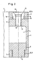
- the upper part of the illustration according to FIG. 2 shows the connection between the coupling element 5 of the fastening arm 2 and the coupling element 8 of the pivot bearing arm 1, which carries the expanding coupling pin 10.
- the spewing wing parts 16 of the expanding coupling pin are 10 pivoted radially outwards, specifically because of the expansion head 20 of the screw 19.
- the expansion wing parts 16 engage with their external serration 13 ′ in the corresponding serration 14 of the coupling opening 11 of the coupling element 5.
- the annular shoulder 18 is located in the annular groove 17 that can be seen in FIG. 1.
Landscapes
- Engineering & Computer Science (AREA)
- Mechanical Engineering (AREA)
- Clamps And Clips (AREA)
- Hinges (AREA)
- Adhesive Tapes (AREA)
Claims (15)
Priority Applications (3)
| Application Number | Priority Date | Filing Date | Title |
|---|---|---|---|
| EP86100693A EP0230487B1 (fr) | 1986-01-20 | 1986-01-20 | Penture, en particulier pour volets |
| DE8686100693T DE3670523D1 (de) | 1986-01-20 | 1986-01-20 | Band, insbesondere ladenband. |
| AT86100693T ATE52128T1 (de) | 1986-01-20 | 1986-01-20 | Band, insbesondere ladenband. |
Applications Claiming Priority (1)
| Application Number | Priority Date | Filing Date | Title |
|---|---|---|---|
| EP86100693A EP0230487B1 (fr) | 1986-01-20 | 1986-01-20 | Penture, en particulier pour volets |
Publications (2)
| Publication Number | Publication Date |
|---|---|
| EP0230487A1 EP0230487A1 (fr) | 1987-08-05 |
| EP0230487B1 true EP0230487B1 (fr) | 1990-04-18 |
Family
ID=8194841
Family Applications (1)
| Application Number | Title | Priority Date | Filing Date |
|---|---|---|---|
| EP86100693A Expired - Lifetime EP0230487B1 (fr) | 1986-01-20 | 1986-01-20 | Penture, en particulier pour volets |
Country Status (3)
| Country | Link |
|---|---|
| EP (1) | EP0230487B1 (fr) |
| AT (1) | ATE52128T1 (fr) |
| DE (1) | DE3670523D1 (fr) |
Families Citing this family (3)
| Publication number | Priority date | Publication date | Assignee | Title |
|---|---|---|---|---|
| DE19962753C2 (de) * | 1999-12-23 | 2003-06-12 | Dorma Gmbh & Co Kg | Scharnierband für Schwenktüren |
| FR2908443A1 (fr) * | 2006-11-10 | 2008-05-16 | Patrick Bessou | Ensemble paumelle femelle reglable et support de fixation |
| IT1399206B1 (it) * | 2010-03-31 | 2013-04-11 | Termoisover Ind S R L | Cerniera per persiane utilizzabile su fabbricati esistenti ai quali viene applicato un isolamento termico a cappotto |
Family Cites Families (4)
| Publication number | Priority date | Publication date | Assignee | Title |
|---|---|---|---|---|
| DE283270C (fr) * | ||||
| ES218561Y (es) * | 1975-02-07 | 1977-01-16 | Un gozne o bisagra. | |
| AT378989B (de) * | 1981-12-21 | 1985-10-25 | Mayer & Co Riegel Beschlag | Laengenverstellbares ladenband fuer einen fenster- oder tùrladen |
| FR2524535B1 (fr) * | 1982-03-30 | 1987-10-30 | Desarmaux Merle Ste Indle | Dispositif de montage et d'articulation reglable pour volets et similaires, adaptable notamment sur un gond |
-
1986
- 1986-01-20 AT AT86100693T patent/ATE52128T1/de not_active IP Right Cessation
- 1986-01-20 EP EP86100693A patent/EP0230487B1/fr not_active Expired - Lifetime
- 1986-01-20 DE DE8686100693T patent/DE3670523D1/de not_active Expired - Fee Related
Also Published As
| Publication number | Publication date |
|---|---|
| EP0230487A1 (fr) | 1987-08-05 |
| ATE52128T1 (de) | 1990-05-15 |
| DE3670523D1 (de) | 1990-05-23 |
Similar Documents
| Publication | Publication Date | Title |
|---|---|---|
| EP0868586B1 (fr) | Charniere | |
| DE3834053C2 (fr) | ||
| DE3820338C2 (fr) | ||
| EP0058220A1 (fr) | Ferrure d'assemblage | |
| EP0097766B1 (fr) | Charnière pour meuble | |
| EP0386342A1 (fr) | Vantail de porte, en particulier dans une séparation pour douche | |
| EP0715085B1 (fr) | Dispositif de fixation | |
| DE4301873A1 (de) | Scharnier mit Schenkel und Halterung zur Schnellbefestigung | |
| EP0275405B1 (fr) | Ferrure de connexion en deux parties | |
| DE3627170C1 (de) | Scharnierarm fuer ein Moebelscharnier o.dgl.,mit Grundplatte direkt oder indirekt verbindbar | |
| EP0230487B1 (fr) | Penture, en particulier pour volets | |
| DE3245671A1 (de) | Stulpschienen-treibstangeneinheit | |
| EP0467122B1 (fr) | Douille pour broches de ferrures ou charnières | |
| DE3637244A1 (de) | Scharnier | |
| EP1091069B1 (fr) | Charnière avec deux éléments relativement pivotants l'un par rapport à l'autre le long d'un axe commun de pivotement | |
| DE3335306A1 (de) | Fehlbedienungssperre fuer treibstangenbeschlaege | |
| DE2554133C2 (de) | Scharnier | |
| DE3333702A1 (de) | Fehlbedienungssperre fuer treibstangenbeschlaege | |
| DE2554129C2 (de) | Möbelscharnier | |
| EP0590258B1 (fr) | Ferrure de charnière pour fenêtres, portes ou similaires | |
| EP0205026B1 (fr) | Bras de charnière pour une charnière de meuble avec plaque de montage | |
| EP1404937B1 (fr) | Ensemble d'armature comportant un ressort d'encliquetage | |
| DE19810365C2 (de) | Scharnier | |
| DE2751148A1 (de) | Auf links- oder rechts-anschlag umstellbares drehstangen-moebelschloss | |
| EP0843061B1 (fr) | Ferrure pour fenêtre |
Legal Events
| Date | Code | Title | Description |
|---|---|---|---|
| PUAI | Public reference made under article 153(3) epc to a published international application that has entered the european phase |
Free format text: ORIGINAL CODE: 0009012 |
|
| AK | Designated contracting states |
Kind code of ref document: A1 Designated state(s): AT BE CH DE IT LI NL |
|
| 17P | Request for examination filed |
Effective date: 19870916 |
|
| 17Q | First examination report despatched |
Effective date: 19881117 |
|
| GRAA | (expected) grant |
Free format text: ORIGINAL CODE: 0009210 |
|
| AK | Designated contracting states |
Kind code of ref document: B1 Designated state(s): AT BE CH DE IT LI NL |
|
| ITF | It: translation for a ep patent filed |
Owner name: BARZANO' E ZANARDO MILANO S.P.A. |
|
| REF | Corresponds to: |
Ref document number: 52128 Country of ref document: AT Date of ref document: 19900515 Kind code of ref document: T |
|
| REF | Corresponds to: |
Ref document number: 3670523 Country of ref document: DE Date of ref document: 19900523 |
|
| ITTA | It: last paid annual fee | ||
| PG25 | Lapsed in a contracting state [announced via postgrant information from national office to epo] |
Ref country code: LI Effective date: 19910131 Ref country code: CH Effective date: 19910131 Ref country code: BE Effective date: 19910131 |
|
| PLBE | No opposition filed within time limit |
Free format text: ORIGINAL CODE: 0009261 |
|
| STAA | Information on the status of an ep patent application or granted ep patent |
Free format text: STATUS: NO OPPOSITION FILED WITHIN TIME LIMIT |
|
| 26N | No opposition filed | ||
| PG25 | Lapsed in a contracting state [announced via postgrant information from national office to epo] |
Ref country code: NL Effective date: 19910801 |
|
| NLV4 | Nl: lapsed or anulled due to non-payment of the annual fee | ||
| REG | Reference to a national code |
Ref country code: CH Ref legal event code: PL |
|
| PGFP | Annual fee paid to national office [announced via postgrant information from national office to epo] |
Ref country code: AT Payment date: 19930126 Year of fee payment: 8 |
|
| PGFP | Annual fee paid to national office [announced via postgrant information from national office to epo] |
Ref country code: DE Payment date: 19930311 Year of fee payment: 8 |
|
| PG25 | Lapsed in a contracting state [announced via postgrant information from national office to epo] |
Ref country code: AT Effective date: 19940120 |
|
| PG25 | Lapsed in a contracting state [announced via postgrant information from national office to epo] |
Ref country code: DE Effective date: 19941001 |
|
| PG25 | Lapsed in a contracting state [announced via postgrant information from national office to epo] |
Ref country code: IT Free format text: LAPSE BECAUSE OF NON-PAYMENT OF DUE FEES;WARNING: LAPSES OF ITALIAN PATENTS WITH EFFECTIVE DATE BEFORE 2007 MAY HAVE OCCURRED AT ANY TIME BEFORE 2007. THE CORRECT EFFECTIVE DATE MAY BE DIFFERENT FROM THE ONE RECORDED. Effective date: 20050120 |