EP0229891A2 - System zum Positionieren eines Kopfes für Floppy-Disk-Antriebe - Google Patents
System zum Positionieren eines Kopfes für Floppy-Disk-Antriebe Download PDFInfo
- Publication number
- EP0229891A2 EP0229891A2 EP86114617A EP86114617A EP0229891A2 EP 0229891 A2 EP0229891 A2 EP 0229891A2 EP 86114617 A EP86114617 A EP 86114617A EP 86114617 A EP86114617 A EP 86114617A EP 0229891 A2 EP0229891 A2 EP 0229891A2
- Authority
- EP
- European Patent Office
- Prior art keywords
- signal
- digital filter
- position error
- head
- magnetic head
- Prior art date
- Legal status (The legal status is an assumption and is not a legal conclusion. Google has not performed a legal analysis and makes no representation as to the accuracy of the status listed.)
- Ceased
Links
- 230000005291 magnetic effect Effects 0.000 claims abstract description 32
- 230000006641 stabilisation Effects 0.000 claims abstract description 16
- 238000011105 stabilization Methods 0.000 claims abstract description 16
- 238000010586 diagram Methods 0.000 description 15
- 238000005070 sampling Methods 0.000 description 11
- 230000003068 static effect Effects 0.000 description 6
- 230000000087 stabilizing effect Effects 0.000 description 1
- 230000001360 synchronised effect Effects 0.000 description 1
- 230000001960 triggered effect Effects 0.000 description 1
Images


Classifications
-
- G—PHYSICS
- G11—INFORMATION STORAGE
- G11B—INFORMATION STORAGE BASED ON RELATIVE MOVEMENT BETWEEN RECORD CARRIER AND TRANSDUCER
- G11B5/00—Recording by magnetisation or demagnetisation of a record carrier; Reproducing by magnetic means; Record carriers therefor
- G11B5/48—Disposition or mounting of heads or head supports relative to record carriers ; arrangements of heads, e.g. for scanning the record carrier to increase the relative speed
- G11B5/54—Disposition or mounting of heads or head supports relative to record carriers ; arrangements of heads, e.g. for scanning the record carrier to increase the relative speed with provision for moving the head into or out of its operative position or across tracks
- G11B5/55—Track change, selection or acquisition by displacement of the head
- G11B5/5521—Track change, selection or acquisition by displacement of the head across disk tracks
- G11B5/5526—Control therefor; circuits, track configurations or relative disposition of servo-information transducers and servo-information tracks for control thereof
- G11B5/553—Details
- G11B5/5547—"Seek" control and circuits therefor
Definitions
- the present invention relates to a head positioning system which drives a magnetic head from a current track to a target in the radial direction of a magnetic disk. More particularly, the present invention relates to a head positioning system for floppy disk drives employing a closed loop servo control for positioning the magnetic head.
- a track density is required to increase, i.e. the track width should be reduced.
- the open loop head positioning system cannot realize a drastic reduction in the track width since the reduction of the drive pitch of the step motor is mechanically limited and the track eccentricity cannot be negligible in the high track density.
- a head positioning system employing the closed loop servo for the floppy disk drive is proposed in Japanese Patent Disclosure No. 58-151613.
- each of a plurality of tracks is divided into a plurality of sectors.
- the servo information is recorded at the leading portion of each of the sectors.
- a ma g ne- tic head reads the servo information to supply it to a closed loop servo controller.
- the controller enables a fine step motor to move the magnetic head in the radial direction of the disk to position near the center line of a target track in accordance with the servo information.
- the fine step motor moves the magnetic head by a pitch narrower than the track width every time the servo information is obtained.
- the fine track following operation is carried out by using only the servo information obtained from the leading portion of each of the sectors.
- the sampling time of the servo information is determined by the disk rotation speed and the number of sectors; both of which is predetermined. Accordingly, the sampling time cannot be shortened and is too long to make the magnetic head follow the second component of the track eccentricity with high accuracy. As a result, the conventional head positioning system cannot accurately position the magnetic head at the center line of the target track so that the track density is relatively low.
- an object of the present invention is to provide a head positioning system capable of positioning the magnetic head at the center line of a target track with high accuracy even; if the target track is eccentric.
- Another object of the present invention is to provide a head positioning system capable of increasing the track density of the disk.
- a head positioning system is featured by having a compensation digital filter for generating a compensation signal whose frequency is synchronized with the track eccentricity.
- Fig. 1 shows a head positioning system according to a first embodiment of the present invention.
- a position error detector I is provided with a reference signal r and a head position signal x to generate a position error signal e.
- the reference signal r represents a target track on which a magnetic head 7 is to be positioned.
- the head position signal x obtained from a magnetic head 7 which reads a servo information from servo areas 8a of a floppy disk 8.
- a record area of the floppy disk 8 is divided into 32 sectors each having the servo area 8a at its leading portion.
- the position error detector I generates the position error signal e, which represents a difference between the reference signal r and the head position signal x, and supplies the signal e to an integrator 2 and a stabilization digital filter 4 every sampling time T.
- the integrator 2 integrates the error signal e every sampling time T to generate an integrated value a.
- the integrated value a is supplied to a second component sine-wave digital filter 3 and the stabilization digital filter 4.
- the sine-wave digital filter 3 generates a sine-wave whose frequency is the same as the second component of the track eccentricity.
- the second component is caused by temperature change, humidity change, and so on.
- the second component eccentricity means that the track is deformed to be oval. Accordingly, the second component has a frequency twice the disk rotation frequency. Since the disk rotation frequency is set at 5 Hz, the digital filter generates a sine-wave of 10 Hz.
- the sine-wave generation is triggered by an impulse input.
- the stabilization digital filter 4 calculates an equilibrium point u in accordance with the error signal e, the integrated value a and the outputs b 1 and b 2 of the digital filter 3.
- the stabilization digital filter 4 is a phase-compensator for stabilizing the feedback control system, as known in the art.
- the motor driver 5 supplies drive currents d and d' to each phases of a 2-phase linear step motor 6 in correspondence to the equilibrium point u. As is well known, an appropriate combination of the 2-phase motor currents can stop the step motor at an arbitrary position. The motor driver 5 thus moves the motor 6 to position the magnetic head 7 at a target track.
- the magnetic head 7 reads the servo information from the servo area 8a at the next sampling time T.
- the updated head position signal x is supplied to the position error detector I.
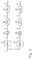
- Fig. 2 shows a block diagram of the motor driver 5 which includes ROM's 51 and 51' for storing current values f and f' to be applied to the two phases of the- motor 6. Appropriate current values f and f' are read out corresponding to the equilibrium point u.
- the current values f and f' in the digital form are converted into the analog form by digital to analog (D/A) converters 52 and 52'.
- Low pass filters (LPF) 53 and 53' cut off the higher frequencies than the Nyquist rate of the output signals g and g' of the D/A converters 52 and 52'.
- Amplifiers 54 and 54' amplify the output signals h and h' of the LPFs 53 and 53' to generate the drive currents d and d'.
- D/A digital to analog
- the current value f is set from +0.1 to 0 ampere and f is set from +0.1 to +(0.1x1 ⁇ 2) ampere corresponding to the equlibrium point from the reference point 0 to 8/ ⁇ , respectively, wherein ⁇ is tooth pitch of the step motor.
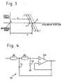
- Fig. 4 shows a circuit diagram of the LPF 53 shown in Fig. 2.
- the other LPF 53' is the same as the LPF 53.
- the LPF 53 includes resistors R 1 and R 2 , condensors C 1 and C 2 and a differential amplifier 531, as is well known in the art.
- coefficient matrixes A, B and C are as follows: wherein
- state vector X(NT) and output vector Y(NT) are represented as follows: wherein B represents a velocity of the magnetic head 7.
- B represents a velocity of the magnetic head 7.
- the system represented by the equations (6-a) and (6-b) is controllable and observable with the observability indices "2".
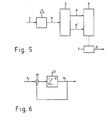
- Fig. 6 illustrates the function of the integrator 2 by using an operator z of the Z-transform.
- the integrator 2 includes an adder 21 and a shift register 22.
- the shift register 22 integrates the output of the adder 21 and outputs the integrated value a every sampling time T.
- Fig. 7 is a block diagram representing a transfer function of the second component sine-wave digital filter 3 by using an operator of Z-transform.
- the sine-wave digital filter 3 is provided for enabling the magnetic head to follow the second component of the track eccentricity even if the sampling frequency is relatively low.
- the pulse transfer function G sin(z) from the integrated value a to the output b is represented by real constants m1 , m2, m3, m4, m5 and m6 as follows:
- the magnetic head follows the center line of a target track, i.e., the track eccentricity, with high accuracy.
- Fig. 8 is a block diagram representing a transfer function of the stabilization digital filter 4.
- the system shown in Fig. 5 is controllable and observable and its observability indices is "2"
- the system can be stabilized by first order stabilization digital filter, as known in the art.
- (z) in formula (8) is "7".
- real constants 11 to 19 are determined in accordance with the observer theory or the state feedback theory.
- the polynomial ⁇ (z) in formula (8) is arbitrarily determined by the real constants 11 to 19. Accordingly, the system shown in Fig. 1 can be stabilized.
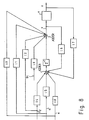
- Fig. 9 shows a second embodiment of the present invention in which the same elements and signals in the figure bear the same reference numerals as in Fig. 1.
- the position error signal e from the position error detector 1 is supplied to a compensation digital filter 9 and a stabilization digital filter 10.
- the compensation digital filter 9 has a plurality of outputs i 1 to i 32 which corresponds to the number of sectors.
- the stabilization digital filter 10 calculates the equilibrium point u and supplies it to the motor driver 5.
- the compensation digital filter 9 includes a plurality of shift registers 901 to 932.
- the number of the shift registers is the same as that of the sectors on the floppy ⁇ disk 8, i.e., "32".
- the contents of the shift registers 901 to 932 are cyclically shifted to the next shift registers, respectively, in synchronization with the sampling timing T.
- the content of the shift register 932 is added to the position error signal e and stored in the shift register 901. Accordingly, the position error signal obtained the time 32T before and the current position error signal e is added and stored to the shift register 901.
- Compensation digital filter 9 is represented as follows:
- the outputs i1 to i32 of the shift registers 901 to 932 are supplied to the stabilization digital filter 10.
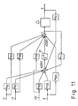
- Fig. 11 is a block diagram representing a transfer function of the stabilization digital filter 10 by using the operator z of the z-transform.
- the controlled system whose pulse transfer function is represented by equations (6-a), (6-b), and (9), is also controllable and observable, and its observability indices are "z". Therefore, the system can be stabilized by determining real constants m 001 to m 030 , m 101 to m 133 , m f1 and mf2 at appropriate values.
- the position error signal does not include the frequency components of 0, 20, 30,.... That is, the magnetic head follows the track eccentricity.
- the functions of the sine-wave digital filter 3, the compensation digital filter 9 and the stabilization digital filter 4 and 10 can be carried out by means of micro-processor by solving a difference equation.
- the head positioning system according to the present invention can position the magnetic head at the center line of a target track with high accuracy. As a result, three times the track density can be achieved compared with that of a conventional floppy disk drive.
Landscapes
- Moving Of The Head To Find And Align With The Track (AREA)
Applications Claiming Priority (4)
| Application Number | Priority Date | Filing Date | Title |
|---|---|---|---|
| JP60234544A JPH087957B2 (ja) | 1985-10-22 | 1985-10-22 | 磁気ヘツドのデイジタル位置決め制御装置 |
| JP234544/85 | 1985-10-22 | ||
| JP30709/86 | 1986-02-17 | ||
| JP3070986A JPS62189682A (ja) | 1986-02-17 | 1986-02-17 | フロツピイデイスクフアイルの磁気ヘツド位置決め制御装置 |
Publications (2)
| Publication Number | Publication Date |
|---|---|
| EP0229891A2 true EP0229891A2 (de) | 1987-07-29 |
| EP0229891A3 EP0229891A3 (de) | 1988-08-17 |
Family
ID=26369114
Family Applications (1)
| Application Number | Title | Priority Date | Filing Date |
|---|---|---|---|
| EP86114617A Ceased EP0229891A3 (de) | 1985-10-22 | 1986-10-22 | System zum Positionieren eines Kopfes für Floppy-Disk-Antriebe |
Country Status (2)
| Country | Link |
|---|---|
| US (1) | US4788608A (de) |
| EP (1) | EP0229891A3 (de) |
Cited By (6)
| Publication number | Priority date | Publication date | Assignee | Title |
|---|---|---|---|---|
| EP0302683A3 (en) * | 1987-08-06 | 1989-12-06 | International Business Machines Corporation | A method of, and an apparatus for, controlling the position of a data transducer head |
| EP0361488A3 (de) * | 1988-09-28 | 1991-01-30 | Nec Corporation | Magnetisches Plattengerät mit einer Schaltungsanordnung zur Detektion von auf einer magnetischen Platte aufgezeichneten Servo-Informationen |
| EP0323154A3 (de) * | 1987-12-24 | 1991-07-24 | Matsushita Electric Industrial Co., Ltd. | Datenwandler-Positionssteuerungssystem für Plattenspeicher-Antriebssystem |
| EP0456348A3 (en) * | 1990-05-08 | 1992-09-09 | International Business Machines Corporation | Method and apparatus for controlling head position in disk storage apparatus |
| WO1993015447A1 (de) * | 1992-01-22 | 1993-08-05 | Hurth Maschinen Und Werkzeuge Gmbh | Regelungs-anordnung |
| SG98412A1 (en) * | 1999-06-30 | 2003-09-19 | Seagate Technology Llc | System and method to minimize bearing pivot effect in disc drive actuator |
Families Citing this family (16)
| Publication number | Priority date | Publication date | Assignee | Title |
|---|---|---|---|---|
| JP2551043B2 (ja) * | 1987-10-31 | 1996-11-06 | ソニー株式会社 | トラッキング制御装置 |
| JP2595631B2 (ja) * | 1988-03-17 | 1997-04-02 | 日本ビクター株式会社 | 記録再生素子の位置制御方式 |
| US5032776A (en) * | 1988-11-10 | 1991-07-16 | Unisys Corp. | Attenuation filter |
| ES2129414T3 (es) * | 1990-09-18 | 1999-06-16 | Rodime Plc | Sistema de control digital para unidades de disco. |
| US5402280A (en) * | 1992-05-11 | 1995-03-28 | Quantum Corp. | Method and apparatus for runout correction due to disk slip or spindle imbalance |
| US5377096A (en) * | 1992-12-16 | 1994-12-27 | International Business Machines Corporation | Digital actuator controller using low-pass filter |
| US5880902A (en) * | 1996-04-09 | 1999-03-09 | International Business Machines Corporation | Method and apparatus for adaptively calibrating disk drive performance based on real time performance monitoring |
| WO2000051125A1 (en) | 1999-02-22 | 2000-08-31 | Seagate Technology Llc | Compensation for repeatable runout error |
| US6023145A (en) * | 1999-04-21 | 2000-02-08 | Guzik Technical Enterprises | Head and disk tester with a thermal drift-compensated closed-loop positioning system |
| US6563663B1 (en) | 1999-05-07 | 2003-05-13 | Seagate Technology Llc | Repeatable runout compensation using iterative learning control in a disc storage system |
| JP2000331445A (ja) * | 1999-05-19 | 2000-11-30 | Nec Corp | ディスク装置のヘッド位置決め制御装置 |
| JP2003505818A (ja) | 1999-07-23 | 2003-02-12 | シーゲイト テクノロジー エルエルシー | パラメータがスケジュールされている学習アルゴリズムを使用した再現可能なランナウト補正 |
| US6952320B1 (en) | 1999-12-16 | 2005-10-04 | Seagate Technology Llc | Virtual tracks for repeatable runout compensation |
| US6937424B2 (en) * | 2003-05-12 | 2005-08-30 | Hitachi Global Storage Technologies Netherlands N.V. | Repeatable runout (RRO) compensation methods and apparatus for data storage devices |
| US7139150B2 (en) * | 2004-02-10 | 2006-11-21 | Marvell International Ltd. | Method and system for head position control in embedded disk drive controllers |
| US10651281B1 (en) | 2018-12-03 | 2020-05-12 | Globalfoundries Inc. | Substrates with self-aligned buried dielectric and polycrystalline layers |
Family Cites Families (6)
| Publication number | Priority date | Publication date | Assignee | Title |
|---|---|---|---|---|
| NL7314267A (nl) * | 1973-10-17 | 1975-04-21 | Philips Nv | Registratiedrager waarop informatie is aangebracht in een optisch uitleesbare struktuur. |
| US3881184A (en) * | 1974-05-28 | 1975-04-29 | Ibm | Adaptive digital servo system |
| US4135217A (en) * | 1976-11-02 | 1979-01-16 | Xerox Corporation | Utilization of stored run-out information in a track following servo system |
| US4414497A (en) * | 1981-01-22 | 1983-11-08 | Verbatim Corporation | Digitally controllable electronic damper |
| US4518904A (en) * | 1984-01-25 | 1985-05-21 | Rodime Plc | Stepper motor control for data disk system |
| US4616276A (en) * | 1985-07-16 | 1986-10-07 | International Business Machines Corporation | Disk file servo control system with fast reduction of repeatable head position error |
-
1986
- 1986-10-22 US US06/921,514 patent/US4788608A/en not_active Expired - Lifetime
- 1986-10-22 EP EP86114617A patent/EP0229891A3/de not_active Ceased
Cited By (6)
| Publication number | Priority date | Publication date | Assignee | Title |
|---|---|---|---|---|
| EP0302683A3 (en) * | 1987-08-06 | 1989-12-06 | International Business Machines Corporation | A method of, and an apparatus for, controlling the position of a data transducer head |
| EP0323154A3 (de) * | 1987-12-24 | 1991-07-24 | Matsushita Electric Industrial Co., Ltd. | Datenwandler-Positionssteuerungssystem für Plattenspeicher-Antriebssystem |
| EP0361488A3 (de) * | 1988-09-28 | 1991-01-30 | Nec Corporation | Magnetisches Plattengerät mit einer Schaltungsanordnung zur Detektion von auf einer magnetischen Platte aufgezeichneten Servo-Informationen |
| EP0456348A3 (en) * | 1990-05-08 | 1992-09-09 | International Business Machines Corporation | Method and apparatus for controlling head position in disk storage apparatus |
| WO1993015447A1 (de) * | 1992-01-22 | 1993-08-05 | Hurth Maschinen Und Werkzeuge Gmbh | Regelungs-anordnung |
| SG98412A1 (en) * | 1999-06-30 | 2003-09-19 | Seagate Technology Llc | System and method to minimize bearing pivot effect in disc drive actuator |
Also Published As
| Publication number | Publication date |
|---|---|
| EP0229891A3 (de) | 1988-08-17 |
| US4788608A (en) | 1988-11-29 |
Similar Documents
| Publication | Publication Date | Title |
|---|---|---|
| EP0229891A2 (de) | System zum Positionieren eines Kopfes für Floppy-Disk-Antriebe | |
| EP0000261B1 (de) | Schaltung zur direkten und rückgekoppelten Steuerung einer Positioniereinrichtung | |
| EP0003070B1 (de) | Zeitoptimale digitale Steuerung zum Positionieren unter Verwendung eines Modells der Vorrichtung | |
| Oswald | Design of a disk file head-positioning servo | |
| US5065263A (en) | Track following transducer position control system for a disk storage drive system | |
| US6614612B1 (en) | Embedded programmable filter for disk drive velocity control | |
| KR890010889A (ko) | 디스크장치의 위치결정장치 | |
| JPS6216464B2 (de) | ||
| WO1997004446A2 (en) | Sliding mode control of a magnetoresistive read head for magnetic recording | |
| JPH0738136B2 (ja) | 位置決め制御装置 | |
| WO2001001401A1 (en) | Method and apparatus for maintaining servo stability during actuator saturation | |
| US4831471A (en) | System for positioning a magnetic head at a center line of a floppy disk track | |
| US4405956A (en) | Tracking apparatus for read/write head | |
| EP0537990A1 (de) | Antriebgerät mit Vorrichtung zur Steuerung eines bewegbaren Betätitungselementes | |
| US5859743A (en) | Method and apparatus for fast positioning a head of a recording device | |
| JPH087957B2 (ja) | 磁気ヘツドのデイジタル位置決め制御装置 | |
| JP2636833B2 (ja) | 光ディスク装置 | |
| JPH07105122B2 (ja) | ヘッド位置制御方法および装置 | |
| JPS62120677A (ja) | フロツピデイスクサ−ボ装置 | |
| JPS627398A (ja) | ステツプモ−タのデイジタル位置決め制御装置 | |
| JP2910396B2 (ja) | 記録再生装置 | |
| JPS62189682A (ja) | フロツピイデイスクフアイルの磁気ヘツド位置決め制御装置 | |
| JPS584362B2 (ja) | 位置決め方式 | |
| JPH0222821Y2 (de) | ||
| JPS63110988A (ja) | 回転速度制御装置 |
Legal Events
| Date | Code | Title | Description |
|---|---|---|---|
| PUAI | Public reference made under article 153(3) epc to a published international application that has entered the european phase |
Free format text: ORIGINAL CODE: 0009012 |
|
| 17P | Request for examination filed |
Effective date: 19861031 |
|
| AK | Designated contracting states |
Kind code of ref document: A2 Designated state(s): DE FR GB NL |
|
| PUAL | Search report despatched |
Free format text: ORIGINAL CODE: 0009013 |
|
| AK | Designated contracting states |
Kind code of ref document: A3 Designated state(s): DE FR GB NL |
|
| 17Q | First examination report despatched |
Effective date: 19900328 |
|
| STAA | Information on the status of an ep patent application or granted ep patent |
Free format text: STATUS: THE APPLICATION HAS BEEN REFUSED |
|
| 18R | Application refused |
Effective date: 19920720 |
|
| APAF | Appeal reference modified |
Free format text: ORIGINAL CODE: EPIDOSCREFNE |
|
| RIN1 | Information on inventor provided before grant (corrected) |
Inventor name: TSUJISAWA, TAKAHIKOC/O NEC CORPORATION |