EP0000261B1 - Schaltung zur direkten und rückgekoppelten Steuerung einer Positioniereinrichtung - Google Patents
Schaltung zur direkten und rückgekoppelten Steuerung einer Positioniereinrichtung Download PDFInfo
- Publication number
- EP0000261B1 EP0000261B1 EP78300061A EP78300061A EP0000261B1 EP 0000261 B1 EP0000261 B1 EP 0000261B1 EP 78300061 A EP78300061 A EP 78300061A EP 78300061 A EP78300061 A EP 78300061A EP 0000261 B1 EP0000261 B1 EP 0000261B1
- Authority
- EP
- European Patent Office
- Prior art keywords
- signal
- velocity
- phase
- positioning system
- error
- Prior art date
- Legal status (The legal status is an assumption and is not a legal conclusion. Google has not performed a legal analysis and makes no representation as to the accuracy of the status listed.)
- Expired
Links
- 230000004044 response Effects 0.000 claims description 19
- 230000001133 acceleration Effects 0.000 claims description 17
- 230000008859 change Effects 0.000 claims description 11
- 230000003247 decreasing effect Effects 0.000 claims description 4
- 125000004122 cyclic group Chemical group 0.000 claims description 3
- 230000007274 generation of a signal involved in cell-cell signaling Effects 0.000 claims description 2
- 238000000034 method Methods 0.000 description 15
- 230000008569 process Effects 0.000 description 12
- 230000000737 periodic effect Effects 0.000 description 10
- 230000002441 reversible effect Effects 0.000 description 9
- 230000000694 effects Effects 0.000 description 8
- 230000009471 action Effects 0.000 description 5
- 238000004886 process control Methods 0.000 description 3
- 239000003990 capacitor Substances 0.000 description 2
- 238000012937 correction Methods 0.000 description 2
- 238000001914 filtration Methods 0.000 description 2
- 230000009467 reduction Effects 0.000 description 2
- 238000005070 sampling Methods 0.000 description 2
- 230000002463 transducing effect Effects 0.000 description 2
- 244000182067 Fraxinus ornus Species 0.000 description 1
- 238000012369 In process control Methods 0.000 description 1
- 230000001154 acute effect Effects 0.000 description 1
- 230000004075 alteration Effects 0.000 description 1
- 238000013500 data storage Methods 0.000 description 1
- 230000002939 deleterious effect Effects 0.000 description 1
- 230000001419 dependent effect Effects 0.000 description 1
- 238000013461 design Methods 0.000 description 1
- 238000010965 in-process control Methods 0.000 description 1
- 238000005259 measurement Methods 0.000 description 1
- 230000004048 modification Effects 0.000 description 1
- 238000012986 modification Methods 0.000 description 1
- 238000012827 research and development Methods 0.000 description 1
- 230000000630 rising effect Effects 0.000 description 1
- 229920006395 saturated elastomer Polymers 0.000 description 1
- 230000001052 transient effect Effects 0.000 description 1
Images


Classifications
-
- G—PHYSICS
- G11—INFORMATION STORAGE
- G11B—INFORMATION STORAGE BASED ON RELATIVE MOVEMENT BETWEEN RECORD CARRIER AND TRANSDUCER
- G11B5/00—Recording by magnetisation or demagnetisation of a record carrier; Reproducing by magnetic means; Record carriers therefor
- G11B5/48—Disposition or mounting of heads or head supports relative to record carriers ; arrangements of heads, e.g. for scanning the record carrier to increase the relative speed
- G11B5/54—Disposition or mounting of heads or head supports relative to record carriers ; arrangements of heads, e.g. for scanning the record carrier to increase the relative speed with provision for moving the head into or out of its operative position or across tracks
- G11B5/55—Track change, selection or acquisition by displacement of the head
- G11B5/5521—Track change, selection or acquisition by displacement of the head across disk tracks
- G11B5/5526—Control therefor; circuits, track configurations or relative disposition of servo-information transducers and servo-information tracks for control thereof
- G11B5/553—Details
- G11B5/5547—"Seek" control and circuits therefor
-
- G—PHYSICS
- G05—CONTROLLING; REGULATING
- G05B—CONTROL OR REGULATING SYSTEMS IN GENERAL; FUNCTIONAL ELEMENTS OF SUCH SYSTEMS; MONITORING OR TESTING ARRANGEMENTS FOR SUCH SYSTEMS OR ELEMENTS
- G05B19/00—Programme-control systems
- G05B19/02—Programme-control systems electric
- G05B19/18—Numerical control [NC], i.e. automatically operating machines, in particular machine tools, e.g. in a manufacturing environment, so as to execute positioning, movement or co-ordinated operations by means of programme data in numerical form
- G05B19/19—Numerical control [NC], i.e. automatically operating machines, in particular machine tools, e.g. in a manufacturing environment, so as to execute positioning, movement or co-ordinated operations by means of programme data in numerical form characterised by positioning or contouring control systems, e.g. to control position from one programmed point to another or to control movement along a programmed continuous path
- G05B19/21—Numerical control [NC], i.e. automatically operating machines, in particular machine tools, e.g. in a manufacturing environment, so as to execute positioning, movement or co-ordinated operations by means of programme data in numerical form characterised by positioning or contouring control systems, e.g. to control position from one programmed point to another or to control movement along a programmed continuous path using an incremental digital measuring device
- G05B19/23—Numerical control [NC], i.e. automatically operating machines, in particular machine tools, e.g. in a manufacturing environment, so as to execute positioning, movement or co-ordinated operations by means of programme data in numerical form characterised by positioning or contouring control systems, e.g. to control position from one programmed point to another or to control movement along a programmed continuous path using an incremental digital measuring device for point-to-point control
- G05B19/231—Numerical control [NC], i.e. automatically operating machines, in particular machine tools, e.g. in a manufacturing environment, so as to execute positioning, movement or co-ordinated operations by means of programme data in numerical form characterised by positioning or contouring control systems, e.g. to control position from one programmed point to another or to control movement along a programmed continuous path using an incremental digital measuring device for point-to-point control the positional error is used to control continuously the servomotor according to its magnitude
- G05B19/232—Numerical control [NC], i.e. automatically operating machines, in particular machine tools, e.g. in a manufacturing environment, so as to execute positioning, movement or co-ordinated operations by means of programme data in numerical form characterised by positioning or contouring control systems, e.g. to control position from one programmed point to another or to control movement along a programmed continuous path using an incremental digital measuring device for point-to-point control the positional error is used to control continuously the servomotor according to its magnitude with speed feedback only
-
- G—PHYSICS
- G05—CONTROLLING; REGULATING
- G05B—CONTROL OR REGULATING SYSTEMS IN GENERAL; FUNCTIONAL ELEMENTS OF SUCH SYSTEMS; MONITORING OR TESTING ARRANGEMENTS FOR SUCH SYSTEMS OR ELEMENTS
- G05B2219/00—Program-control systems
- G05B2219/30—Nc systems
- G05B2219/41—Servomotor, servo controller till figures
- G05B2219/41086—Bang bang control
-
- G—PHYSICS
- G05—CONTROLLING; REGULATING
- G05B—CONTROL OR REGULATING SYSTEMS IN GENERAL; FUNCTIONAL ELEMENTS OF SUCH SYSTEMS; MONITORING OR TESTING ARRANGEMENTS FOR SUCH SYSTEMS OR ELEMENTS
- G05B2219/00—Program-control systems
- G05B2219/30—Nc systems
- G05B2219/41—Servomotor, servo controller till figures
- G05B2219/41355—Electro magnetic coil actuator, voice coil
-
- G—PHYSICS
- G05—CONTROLLING; REGULATING
- G05B—CONTROL OR REGULATING SYSTEMS IN GENERAL; FUNCTIONAL ELEMENTS OF SUCH SYSTEMS; MONITORING OR TESTING ARRANGEMENTS FOR SUCH SYSTEMS OR ELEMENTS
- G05B2219/00—Program-control systems
- G05B2219/30—Nc systems
- G05B2219/41—Servomotor, servo controller till figures
- G05B2219/41434—Feedforward FFW
Definitions
- the present invention relates to positioning systems for moving a member between positions in response to a position input command.
- the invention relates particularly to systems in which each such movement, between a current and a target reference position, is completed before a subsequent command is accepted and comprises a single acceleration phase in which such a member is accelerated to a maximum velocity and a single deceleration phase in which said member is decelerated from said maximum velocity to a state of rest at said target reference position.
- a typical positioning application to which the present invention relates is the positioning of a data recording head or heads over a selected track of a magnetic disk file.
- the aspect of this positioning operation which is of interest is the movement of heads between tracks, known as the “track access” or “seek” operation, as opposed to the “track follow” operation which maintains the heads in position over a selected track.
- Time optimal motion between tracks implies maximum acceleration and deceleration of the heads within the physical constraints of the system.
- To control such motion with typical access times of a few tens of milliseconds, and bring the heads to rest on the target track, with an accuracy better than a hundred microns, feedback control of head velocity has been widely employed.
- Velocity control offers a higher performance than position control because velocity is the time derivative of position.
- a typical system for controlling a disk file head access operation is described in an article entitled "Design of a Disk File Head-Positioning Servo" by R. K. Oswald (IBM Journal of Research and Development, Nov 1974, pp 506 to 512). Similar systems directed to the same application are shown, for example in US Patents 2 881 184, 4006394. 4030132 and 4031 443.
- an access operation is controlled by means of a generated reference velocity trajectory representing the required velocity of the heads for deceleration at the maximum attainable rate to a state of rest over the target track.
- a velocity transducer or tachometer measures the actual velocity of the heads and the measured velocity is compared with the reference velocity trajectory and amplified in an error amplifier to provide a velocity error signal.
- the velocity error signal is applied to control the head actuator, typically a voice coil motor, to cause the actual velocity to follow the deceleration curve as closely as possible. Initially, actual velocity is low and the heads are accelerated under open loop (saturated) conditions until the actual velocity equals the reference velocity.
- Control systems for innumerable other applications than position control are also found in the prior art.
- a large variety of control schemes also exist, and these have tended to develop according to the particular application and its unique problems.
- control systems have been developed which have some resemblance to the positioning control system of the present invention.
- Feed- forward control involves predicting the change with time of a manipulated variable necessary to produce the desired change in a controlled variable of the process.
- the feedforward function is based on a model of the process and is applied to the actual system independently of any feedback. Feedforward control is essentially an open-loop technique allowing immediate response to an input command. The accuracy of such control is only as good as that of the process model.
- control and feasible response means provides a feasible response signal, representing the predicted response of the controlled variable to the change of the manipulated variable in accordance with the feedforward control signal.
- the feasible response signal is compared with the actual measured response of the controlled variable to provide an error signal. This error signal is summed with the fed forward manipulated variable to provide fine feedback control of the process.
- feedforward plus feedback control techniques to positioning systems has been proposed in the prior art.
- Systems having both types of control are described in an article "Feed forward can improve feedback controls" by R L Dutchie (Control Engineering, May 1959, pp136-140).
- the position input signals, 9i are arbitrary and may vary continuously.
- the feedforward action consists of simultaneously generating feedforward signals either directly from or directly in response to variations of the input signals. These feed- forward signals are then applied to various points in the main gain path of the control loop. There is no element of prediction over a period of time and relatively complex tachometers and auxiliary servo systems must be used to enable the feedforward signal to respond in real time to variations of the input.
- the velocity feedback loop is Type 1 and the reference velocity trajectory is approximately a ramp so that the velocity error can never be completely eliminated.
- the magnitude of the velocity error is dependent on the overall gain of the feedback loop which also affects the bandwidth of the loop. A compromise is necessary between the reduction of velocity error and the limitations imposed by the mechanical resonances of the system. If the gain is more than unity at a resonance frequency, the system will be unstable. This problem is becoming increasingly acute with the higher frequencies inherent in increased track densities and shortened access ties.
- the present invention offers a solution to the above problems in providing a positioning system, responsive to a position input command to move a member along a predetermined path of travel between a current and a target reference position defined by said command, each such movement being completed before a subsequent command is accepted and comprising a single acceleration phase in which such a member is accelerated to a maximum velocity and a single deceleration phase in which said member is decelerated from said maximum velocity to a state of rest at said target reference position, said system comprising an electrically controlled actuator for moving said member along said predetermined path in response to electrical drive signals and having an input circuit to which said signals are applied, reference signal generating means responsive to said position input command to generate a reference signal at last a portion of which represents the variation with time of a position related attribute of said member for deceleration of said member in a predetermined manner during said deceleration phase, and a feedback control loop including a transducer for providing a signal indicating the value of said position related attribute of said member, error determining means for producing an
- the invention allows time optimal positioning movement while permitting a low bandwidth in the feedback loop by employing in addition to feedback control a type of feedforward control in which the form of the feedforward control signal can be predicted in advance and represents the input to the actuator of a nominal system.
- the invention preferably provides that the bandwidth of said feedback control loop as a whole is arranged to be predominantly below the frequency of said resonances, such that the overall loop gain is substantially below unity at the frequency of said rsonances and that the bandwidth of said feedforward control means is higher than that of said feedback control loop and overlaps the frequency of said resonances. In this way the system is desensitized to high frequency disturbances without loss of performance.
- the present invention also relaxes considerably the constraints on minimum bandwidth required of transducer signals for rapid motion between positions. This further allows normal velocity feedback and the associated velocity transducing circuitry to be dispensed with entirely, if desired, and the more easily derived position information to be employed in the feedback loop.
- the incremental position of the member from equally spaced reference positions along its path of travel can be used.
- said reference signal generating means comprising an integrator for integrating said velocity representation up and down alternately between positive and negative thresholds to generate said reference signal in the form of an incremental position signal.
- said predictive drive signal generating means includes means for reducing the absolute magnitude of said predictive drive signal as a function of velocity during said deceleration phase of said movement.
- This feature enables the system to take account of the back of e.m.f. of a coil type actuator.
- Feedforward control may advantageously be employed both during acceleration and deceleration of the member and to that end it is a preferred feature of the invention to provide a positioning system further comprising phase indicating means far indicating acceleration and deceleration phases of said motion, and means for providing a representation of the velocity of said member, said feedforward control means being connected to receive said phase indications and said velocity representation and being responsive thereto to generate said predictive drive signal comprising an initial portion consisting of a constant component of one polarity and a component of opposite polarity proportional to said velocity representation during the acceleration phase and having a final portion consisting of a constant component of said opposite polarity and a further component of said opposite polarity proportional to said velocity signal during the deceleration phase of said movement.
- FIG. 1 there is shown a preferred positioning system according to the present invention.
- the positioning system controls the positioning of heads 10 relative to information bearing concentric tracks on disks 11 of a schematically illustrated disk file.
- the heads are moved by an actuator 122 of the well known voice coil motor type.
- the mechanical connection between the actuator 12 and heads 10 is schematically indicated by dashed line 13 and includes a carriage (not shown) for supporting the heads.
- the motor 12, the heads 10 and disks 11 together with other support components including the head carriage constitute a mechanical system 14.
- This system as a whole has natural resonance frequencies typically of the order of a few thousand Hertz which, as will be explained further below, may affect the stability of the positioning system, if they are excited and amplified.
- the input circuit of actuator 12 comprises a power amplifier 15 which amplifies an input drive signal to provide a current to the actuator coil.
- a feedforward control signal on line 16 and a feedback control signal on line 17 are summed in summing junction 18 and selectively inverted by inverter 19, depending on the direction of motion, to provide the drive signal to the power amplifier 15.
- the feedforward control signal is generated by feedforward current generator 20, the details of which will be explained below in connection with Figure 3.
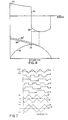
- the feedforward current trajectory is illustrated as waveform 101 of Figure 4 and represents the actuator current required for a nominal system to cause the actuator to move the heads from one track to another in a minimum time. If the actual system were exactly the same as the nominal system, the heads would be moved to the target track and brought to rest there in a minimum time without further control being necessary. However, since there will be parameter differences between the nominal and actual systems, the actual response of the system is measured and fed back for use in a feedback control arrangement to ensure accurate positioning.
- the quantity which is measured to determine the response of the system is velocity.
- the velocity of the heads 10 moving radially across the disk is determined by a velocity transducer circuitry 21 from the integral of the current in the actuator coil and the derivative of a periodic incremental position signal from position transducer circuitry 22.
- a suitable circuit for deriving a velocity signal from these inputs is described in US Patent 3 820 712 (Oswald).
- the position transducer circuitry 22 comprises demodulating circuitry for deriving a position error signal from servo signals read by one of the heads 10 from a dedicated servo surface of one of the disks 11.
- the demodulated position error signal is a cyclic triangular waveform whose zero crossings correspond to track centre.
- the measured velocity signal on line 23 is applied to a summing junction 24 to which is also applied a reference velocity signal on line 25.
- the summing junction forms the difference between the reference velocity signal and the measured velocity signal which is amplified in error amplifier 26 to provide the feedback control signal on line 17.
- the reference velocity signal is conventionally produced in response to a position command at input 30 which loads a difference counter 31 with a value equal to the number of tracks between the current track position of the heads and the target position to which they are to be moved.
- a zero crossing detector 32 As the heads move towards the target position, zero crossings of the position signal from position transducer circuitry 22 are detected by a zero crossing detector 32.
- the zero crossing detector output is a series of pulses each of which decrements the difference counter 31 every time a track is crossed.
- the output of the difference counter 31 is applied on a bus 33 to a digital-to-analog converter 34 which converts the decreasing count to an analog staircase function representative of the instantaneous absolute position error between the heads and the target track.
- An interpolator 35 receives the track crossing pulses from zero crossing detector 32 and the velocity signal on line 23 and provides a "fill-in" signal which is summed in junction 36 to smooth the output of the digital-to-analog converter 34.
- the fill-in signal comprises a falling ramp with a slope proportional to velocity which is reset on every track crossing pulse.
- Circuits for generating such signals are well known and comprise, for example, an integrator for integrating the velocity input signal, which is reset to a predetermined level by the track crossing pulses.
- the smoothed absolute position error signal from junction 36 is applied to a function generator 37 whose output on line 25 is the reference velocity signal as shown in curve 103, Figure 4.
- the function generator 37 modifies the absolute position error signal in shape according to a predetermined function.
- a simple function which has been used is a square root function as this represents the variation of velocity with position for a constant maximum deceleration.
- the relationship of velocity to position may be a more complex function to allow for the effect of the actuator back e.m.f. and to meet servo system stability criteria.
- a circuit for generating a second order function having both a squared and linear term is described below in connection with Figure 2.
- the reference velocity signal from function generator 37 represents the required velocity of the heads 10 while decelerating towards target position with the maximum deceleration attainable by a worst case system.
- the saturation logic 38 is responsive to outputs of the difference counter exceeding a predetermined count to provide a saturation signal to the input of digital-to-analog converter 34 by way of summing junction 40.
- the presence of the saturation signal causes the DAC output to maintain a constant maximum output.
- the corresponding velocity reference signal output on line 25 is also constant under these conditions.
- the velocity of the heads is limited to a predetermined value, known as the "coast" velocity, to protect them from damage in the event of a control failure.
- the anticipate circuit 39 is effective, while the heads are accelerating, to lower slightly the absolute position error signal and thus the reference velocity curve by an amount proportional to velocity.
- the accelerate phase of the motion is indicated by the output of a flip-flop 44 which is set at input 45 at the start of each new seek.
- the output of flip-flop 44 is reset by ground level comparator 41, indicating the sign of the velocity error signal from junction 24 and the end of the accelerate phase.
- the inverted accelerate signal from flip-flop 44 and the saturation signal from logic 38 are applied to an AND gate 42 to produce a "coast" mode signal which indicates the portion of the motion when the heads are at coast velocity. This signal is used in the feedforward current generator 20.
- Another input to the feedforward current generator is a "stop velocity" indication from threshold detector 43. This indicates that the heads have come substantially to rest and that the seek motion is complete.
- the digital-to-analog converter 34 receives the output of difference counter 31 on lines 33 and also the output of saturation logic 38 on additional line 50.
- the digital-to-analog converter output appears on line 51 and is smoothed by the addition of the fill-in signal from interpolator 35 applied at terminal 52.
- the anticipate circuitry 30 comprises a switching transistor 53 responsive to an inverted accelerate mode indication at terminal 54 to inhibit the anticipate function.
- the measured velocity from line 23, Figure 1 is applied at terminal 55 and, when transistor 53 is off, acts to lower slightly the digitial-to-analog converter output level on line 51.
- the function generator 37 of Figure 1 is seen in Figure 2, to comprise an amplifier 60 with a resistive feedback connection to provide a linear term of the required function.
- a two quadrant transconductance multiplier 60 to provide the second order term of the function.
- the output at terminal 62 represents the reference velocity signal on line 25 of Figure 1.
- feedforward current generator 20 together with other associated portions of the system of Figure 1 will now be described in greater detail with reference to Figure 3 and the waveforms of Figure 4.
- the inputs to the circuit of Figure 3 comprise the accelerate signal from comparator 41 at terminal 70, the coast signal from AND gate 42, or the stop velocity signal from detector 43 at terminal 71, the reference velocity signal from function generator 37 at terminal 72, and measured velocity from velocity transducer circuitry 23 at terminals 73 and 74.
- the reference velocity signal at terminal 72 and the measured velocity at terminal 73 are algebraically summed at node 75, corresponding to junction 24 of Figure 1, to produce the velocity error signal.
- An operational amplifier 76 amplifies the velocity error.
- the amplified velocity error is provided at output 79.
- the amplifier output is limited by diodes 77 and 78 to prevent an excessive output signal during accelerate mode when the velocity error is very large.
- the limiting function also ensures that the feedback control signal cannot exceed more than a small predetermined fraction (around 15%) of the feedforward control signal.
- the feedforward current generator comprises a resistive network for providing a current input to an operational amplifier 80, the input being switchable under control of transistors 81 and 82.
- transistor 81 is off and transistor 82 is on.
- a current 1 0 flows from positive supply through resistor 83.
- a current I v proportional to the velocity signal input at terminal 74 is summed with 1 0 so that a combined current I o + I v flows through resistor 84 to the inverting input terminal of amplifier 80. Since transistor 82 is on, current flows from positive supply through resistor 85 to ground and there is no net current through resistor 86.
- a current of magnitude 21 o flows from the input terminal of the amplifier 80 to negative supply through resistor 87.
- both transistors 81 and 82 are off.
- the equal and opposite currents 21a in resistors 86 and 87 cancel out leaving a net current of 1 0 + I v through resistor 84.
- An inverted representation of the waveform of this input current is shown by the dashed line 100 in the right hand half of the upper waveform of Figure 4.
- the feed- forward waveform is reduced to zero when the heads come to rest at the end of a seek by an input to terminal 71 that is provided by the stop velocity detector 43 of Figure 1. Since the input terminal is shared with the coast indication, the switch states of the circuit of Figure 3 are exactly the same as described above in connection with coast mode.
- the velocity factor is introduced to represent the effect of back e.m.f. on current in a high performance electromagnetic coil actuator.
- the back e.m.f. reduces the voltage applied across the coil in the accelerate mode and is added to the voltage applied across the coil in the decelerate mode.
- the amplifier 80 is connected in lag-lead filter configuration with a feedback loop comprising resistors 88 and 89 and capacitor 95.
- the filter modifies the dashed waveform portions 100 of Figure 4 to the shape of continuous line 101.
- the filtering action represents the effect of motor coil inductance on the transient response of coil current. It will be noted that the feedback control voltage from amplifier 76 is effectively summed with the feedforward function at the input of the amplifier 80 rather than at the output as suggested by summing junction 18 of Figure 1. This difference has no practical effect.
- the output waveform 101 as drawn in Figure 4 is that which would be produced in the absence of a feedback control signal.
- a final element of the circuitry of Figure 3 is selective inversion circuitry responsive to input commands indicating forward or reverse direction at terminals 90 and 91.
- Amplifier 94 passes the feedforward signal to output 93 without inversion if line 91, indicating the forward direction of motion is active.
- Amplifier 92 inverts the feedforward signal at output 93 if line 90, indicating the reverse direction of motion, is active.
- This circuitry corresponds to the selective inversion circuit 19 of Figure 1.
- the feedforward current waveform 101 of Figure 4 represents a prediction of the actual current which would exist in the coil of an electromagnetic actuator of a nominal system with full forward then full reverse power applied, less a small margin for control.
- This waveform is fed forward to the power amplifier of the real system and applied as the actuator input current.
- the velocity of the heads is thus caused to follow the trajectory 102 in Figure 4.
- the reference velocity signal 103 is generated, as described in connection with Figures 1 and 2, which represents the variation of velocity with distance necessary to bring the heads to rest on the target track in the minimum time, i.e., with a worst case system operating at full reverse power.
- the reference velocity signal is lowered during acceleration from the dashed curve 103' by the action of the anticipate function.
- the reference curve 103 is compared with the actual velocity 102 to provide a feedback control to provide fine correction to the feed- forward action.
- a feedback control signal is produced, but, because of the large velocity error between curves 102 and 103, is always of the maximum amplitude determined by the limiting diodes of the error amplifier.
- the maximum amplitude error signal is simply added as a small increment to the positive portions of the feedforward function and full forward power is applied to the actuator in open loop fashion.
- the velocity error would disappear entirely, in theory, if the feedforward function were 100% accurate.
- a feedforward function such as waveform 101 is 90% accurate, then the corrective action required from the feedback control loop is only 10% of what would be required without the feed- forward function.
- the gain of the error amplifier and, roughly speaking, the bandwidth of the feedback loop can be reduced by a factor of ten while maintaining the velocity error between curves 102 and 103 as small as before. This considerably reduces the limitations on performance imposed by the mechanical resonance frequencies of the system. If mechanical resonances are not a problem, then the gain can be maintained high and the velocity error very much reduced over what was possible with feedback control alone.
- the gain of the error amplifier is set sufficiently low to reduce the bandwidth of the feedback loop to a few hundred Hertz, well below the lowest resonance frequency of a few thousand Hertz.
- the lag-lead filter formed by resistors 88 and 89 and capacitor 90 in Figure 3 does reduce the bandwidth somewhat, but the effect is insignificant compared with that of the gain of amplifier 76.
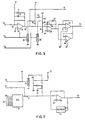
- FIG. 5 there is shown another embodiment of the present invention which makes use of the reduction in feedback loop bandwidth permitted by the addition of feedforward control, to employ a position signal directly as the feedback controlled variable.
- the system of Figure 5 is a system for positioning magnetic heads 210 in relation to tracks on disks 211 of a disk file by means of an electromagnetic voice coil actuator 212.
- the actuator input circuit comprises a power amplifier 215.
- the control signal to the power amplifier input comprises a feedforward signal on line 216 and a feedback signal on line 217 which are summed in junction 218 and selectively inverted by inverter 219 in dependence on the direction of motion.
- the feedforward signal is provided by feed- forward current generator 220 which operates in exactly the same way as the generator 20 of Figure 1, though the inputs to the generator are derived somewhat differently as will be described below.
- a periodic position signal is derived by position transducing circuitry 222 from servo signals ready back by one of the heads 210 from a dedicated servo surface on one of the disks 211.
- the operation of the circuitry and the form of the triangular position signal is exactly the same as for the circuit of Figure 1.
- no velocity transducer circuitry is provided and the periodic position signal is fed back directly to a summing junction 223 for comparison with a reference periodic position on line 224.
- the difference signal from junction 233 is alternately inverted by inverter 228 in dependence on the slope of the reference periodic position signal as detected by slope detector 227.
- the alternately inverted difference signal constitutes the position error signpl and is amplified by error amplifier 225 to provide the feedback control signal.
- the reference periodic position signal is generated by integrating a reference velocity signal repeatedly up and down between predetermined levels in incremental integrator 226, the operation of which will be described below in connection with Figures 6 and 7.
- the reference velocity signal comprises both an accelerate and decelerate portion and feedback control is thus available for the complete duration of the motion.
- the decelerate portion of the reference velocity signal is provided in very similar fashion to Figure 1.
- a difference counter 230 is loaded at terminal 231 with a value representing the number of tracks to be crossed.
- the difference counter is decremented by output pulses from zero crossing detector 232 during the motion and its output converted to an analog function by digitial-to-analog converter 233 and smoothed by fill-in signals from interpolator 234.
- the absolute position error signal thus derived from summing junction 235 is applied to decelerate function generator 236 to produce a reference velocity signal in the manner of Figure 1.
- the accelerate portion of the reference velocity signal is produced somewhat similarly.
- An up counter 240 is set to zero as difference counter 230 is loaded with the difference count.
- a digitial-to-analog converter 242, summing junction 243 and accelerate function generator 244 produce a rising curve representing the required velocity for time optimal motion at successive positions.
- the fill-in signal available from interpolator 234 is inverted in inverter 245 before it is applied to summing junction 243.
- Saturation logic 246 indicates that the up counter has reached a certain predetermined value upon which further counting is inhibited by means of inhibit gate 247.
- the acceleration curve and the deceleration curve are passed through a circuit 248 for passing whichever has the lower value.
- the output of this circuit is the reference velocity curve which is input to the incremental integrator 226.
- a comparator circuit 249 provides an output signal indicating which of the acceleration and deceleration curves is of greater magnitude. This indication identifies the acceleration phase of the motion and is applied to the feedforward generator 220 as an input.
- a second input to the feedforward generator is a "coast" signal, provided by the AND gate 250 from the output of saturation logic 246 and the accelerate signal from comparator 249.
- a second input to the same line is provided by stop velocity detector 251 which detects when the reference velocity effectively falls to zero, indicating that the seek is complete.
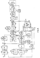
- FIG. 6 A preferred form of incremental integrator and associated switching circuitry suitable for use in the general system of Figure 5 is shown in Figure 6. Waveforms produced by the circuitry of Figure 6 are shown in Figure 7.
- the circuitry of Figure 6 is directly applicable to the system of Figure 5 with the modification that two phases of position signal (both measured and reference) are provided.
- the two phases are of identical form to the sawtooth signals described in the Oswald article, referenced above, but are phase displaced by 90 degrees.
- One signal is normally referred to as the "normal" (in phase) position signal and the other as the "quadrature" position signal.
- the measured in phase and quadrature position signals are applied at terminals 310 and 311 for comparison with reference quadrature position signals N and Q, Figure 7 in junctions 312 and 313 respectively.
- the junctions 312 and 313 correspond to the summing junction 233 of Figure 5 and their outputs are altemately selected by logic to be described to remove the effect on the position error signal of the slope changes and peaks of the position signals.
- a single position error output signal is provided at output 314.
- the two phases of reference periodic position signal are produced by applying the reference velocity signal from circuit 248 ( Figure 5) to the input 319 of a selective inverter 320.
- the inverter is controlled by a signal d, Figure 7, from the normal output of a set/reset flip-flop 321.
- An integrator 322 integrates the alternately inverted reference signal to produce a signal a, Figure 7, which is of triangular form and resembles a single phase position signal.
- the alternation of the flip-flop 321 is controlled by comparators 323 and 324 which compare the magnitude of the integrator output a with predetermined reference levels +V/2 and -V/2.
- the integrator output reverses slope every time one of the levels +V/2 is reached.
- flip-flop 321 The normal and inverted outputs of flip-flop 321 are used to clock respective data/clock flip- flops 325 and 326 which produce output signals e and f as shown in Figure 7. These signals are at half the frequency of signal d and are 90 degrees displaced in phase from each other. They are employed to switch selective inverters 327 and 328 in the generation of reference periodic position signals N and Q.
- the two signals N and Q are produced by applying waveform a to a level shifting network including amplifiers 329 and 330 to produce two intermediate signals N' and Q', Figure 7, which are centered about +V/2 and -V/2 volts respectively.
- Application of these intermediate signals N' and Q' to selective inverters 327 and 328 produce the reference periodic position signals N and Q, Figure 7, which are of twice the amplitude and half the frequency of intermediate signals N' and Q'.
- the reference position signals N and Q from inverters 327 and 328 are next compared with the measured in phase and quadrature position signals in summing junctions 312 and 313.
- a switch circuit 331 is employed to select either the "in phase” or the quadrature position error in dependence on the value of a waveform b, also shown in Figure 7.
- the waveform b is produced by an over- driven comparator 332 in response to the waveform a.
- the switch 331 operates to select alternately only the position error signal derived from central linear portions of the position signals.
- This signal will invert according to whether the slope of the position signals is positive or negative when the comparison is made.
- a selective inverter 333 is interposed between the output of switch 331 and output terminal 314.
- the selective inverter is controlled by a waveform c, shown in Figure 7, derived by data/clock flip-flop 334 from waveform b.
- the system of Figures 5, 6 and 7 employs feedback control only as a fine correction imposed on the basic feedforward control.
- the use of approximate feed- forward control permits the gain and bandwidth of the minor feedback loop to be significantly lower than where feedback control alone is employed.
- this fact permits the use of the position transducer output directly as a feedback controlled variable.
- a position feedback loop is not used where high performance is required since the bandwidth available with position signal feedback is low compared to that of a velocity feedback loop.
- the position transducer circuitry 222 could have a provision for sampling the information from heads 10 at sector times only and for holding sampled position signals, or interpolating between them, between sectors.
- the output of the error amplifier 225 could be sampled and then held or interpolated between sectors. The use of feed- forward control in conjunction with such a sampled system would allow a relatively high performance to be achieved.
Landscapes
- Engineering & Computer Science (AREA)
- Human Computer Interaction (AREA)
- Manufacturing & Machinery (AREA)
- Physics & Mathematics (AREA)
- General Physics & Mathematics (AREA)
- Automation & Control Theory (AREA)
- Control Of Position Or Direction (AREA)
- Moving Of Head For Track Selection And Changing (AREA)
- Feedback Control In General (AREA)
Claims (13)
Applications Claiming Priority (2)
| Application Number | Priority Date | Filing Date | Title |
|---|---|---|---|
| US05/811,350 US4200827A (en) | 1977-06-29 | 1977-06-29 | Positioning system employing feedforward and feedback control |
| US811350 | 1977-06-29 |
Publications (2)
| Publication Number | Publication Date |
|---|---|
| EP0000261A1 EP0000261A1 (de) | 1979-01-10 |
| EP0000261B1 true EP0000261B1 (de) | 1981-10-07 |
Family
ID=25206317
Family Applications (1)
| Application Number | Title | Priority Date | Filing Date |
|---|---|---|---|
| EP78300061A Expired EP0000261B1 (de) | 1977-06-29 | 1978-06-21 | Schaltung zur direkten und rückgekoppelten Steuerung einer Positioniereinrichtung |
Country Status (9)
| Country | Link |
|---|---|
| US (1) | US4200827A (de) |
| EP (1) | EP0000261B1 (de) |
| JP (1) | JPS5412082A (de) |
| AU (1) | AU511484B2 (de) |
| BR (1) | BR7804158A (de) |
| CA (1) | CA1100609A (de) |
| DE (1) | DE2861129D1 (de) |
| ES (1) | ES470846A1 (de) |
| IT (1) | IT1111180B (de) |
Families Citing this family (58)
| Publication number | Priority date | Publication date | Assignee | Title |
|---|---|---|---|---|
| GB2039078B (en) * | 1978-12-27 | 1982-11-24 | Ibm | Sampled data servo positioning system |
| US4284943A (en) * | 1979-02-13 | 1981-08-18 | Electric Machinery Mfg. Company | Apparatus and method for controlling the speed of an induction motor in a closed-loop system |
| FR2466078A1 (fr) * | 1979-09-21 | 1981-03-27 | Cii Honeywell Bull | Procede pour deplacer un systeme mobile par rapport a un support d'informations et dispositif pour le mettre en oeuvre |
| FR2466081A1 (fr) * | 1979-09-21 | 1981-03-27 | Cii Honeywell Bull | Dispositif de mesure de vitesse d'un systeme mobile par rapport a un support d'informations |
| US4321517A (en) * | 1979-12-03 | 1982-03-23 | Storage Technology Corporation | Resonance suppression method |
| JPS57120112A (en) * | 1980-12-22 | 1982-07-27 | Fujitsu Ltd | Locus control method of arm |
| US4459525A (en) * | 1982-02-03 | 1984-07-10 | Ricoh Company, Ltd. | Motor speed control system |
| US4480217A (en) * | 1982-12-14 | 1984-10-30 | Storage Technology Corporation | Automatic velocity calibrator for a velocity servo loop in a magnetic disk drive |
| US4535372A (en) * | 1983-06-29 | 1985-08-13 | Storage Technology Corporation | Position tracking servo control systems and methods |
| US4517503A (en) * | 1983-09-27 | 1985-05-14 | Mechatron Systems, Inc. | Method and apparatus for normalizing the speed of an element positionable by a servomechanism |
| US4642541A (en) * | 1983-10-20 | 1987-02-10 | Memorex Corporation | Track following servo for higher density disk files |
| US4577244A (en) * | 1983-10-20 | 1986-03-18 | Memorex Corporation | Techniques for disk servo |
| US4885516A (en) * | 1983-10-20 | 1989-12-05 | Unisys Corporation | Techniques for disk servo track following |
| JPS60169540A (ja) * | 1984-02-13 | 1985-09-03 | Tohoku Tokushuko Kk | 非強磁性低膨張焼結合金 |
| JPS6220183A (ja) * | 1985-07-18 | 1987-01-28 | Toshiba Corp | トラツク飛び越し制御回路 |
| JPS6224991A (ja) * | 1985-07-26 | 1987-02-02 | 松下電器産業株式会社 | 産業用ロボツト |
| FR2600436B1 (fr) * | 1986-06-20 | 1988-10-07 | Benson Sa | Procede et dispositif de commande de moteur de machine a dessiner |
| JPS6368913A (ja) * | 1986-09-10 | 1988-03-28 | Fujitsu Ltd | サ−ボ制御回路 |
| JPH0783625B2 (ja) * | 1987-04-03 | 1995-09-06 | 三菱電機株式会社 | 検出ヘツドの速度制御装置 |
| JPH0199486A (ja) * | 1987-10-12 | 1989-04-18 | Pioneer Electron Corp | ピックアップ駆動用リニアモータの制御装置 |
| JP2595610B2 (ja) * | 1988-01-27 | 1997-04-02 | 株式会社明電舎 | 位置決め制御装置 |
| US4933785A (en) * | 1988-03-01 | 1990-06-12 | Prairietek Corporation | Disk drive apparatus using dynamic loading/unloading |
| US4926100A (en) * | 1988-06-02 | 1990-05-15 | A. O. Smith Corporation | Zero-torque eddy current motor system and method for controlling same |
| JPH0738136B2 (ja) * | 1988-08-22 | 1995-04-26 | 三菱電機株式会社 | 位置決め制御装置 |
| US4982156A (en) * | 1988-09-02 | 1991-01-01 | Allied-Signal Inc. | Position transducer apparatus and associated circuitry including pulse energized primary winding and pair of waveform sampled secondary windings |
| JPH07120216B2 (ja) * | 1988-10-21 | 1995-12-20 | 新技術事業団 | 位置制御方法 |
| US5049796A (en) * | 1989-05-17 | 1991-09-17 | The United States Of America As Represented By The Administrator Of The National Aeronautics And Space Administration | Robust high-performance control for robotic manipulators |
| US4988932A (en) * | 1989-10-10 | 1991-01-29 | Eastman Kodak Company | Constant velocity servosystem wtih high positional accuracy |
| JPH03161248A (ja) * | 1989-11-15 | 1991-07-11 | Okuma Mach Works Ltd | Nc旋盤用刃物台の割出し制御装置 |
| US5345348A (en) * | 1990-06-29 | 1994-09-06 | Kabushiki Kaisha Toshiba | Controlling the moving speed of a magnetic head by varying the gain in response to the sign of the error signal |
| JP3164580B2 (ja) * | 1990-09-27 | 2001-05-08 | 豊田工機株式会社 | ディジタルサーボ制御装置 |
| US5101145A (en) * | 1991-02-01 | 1992-03-31 | Allen-Bradley Company, Inc. | Velocity proportional integral regulator with negative feedforward to control response of torque disturbances |
| US5459383A (en) * | 1991-02-07 | 1995-10-17 | Quantum Corporation | Robust active damping control system |
| US5329409A (en) * | 1991-07-24 | 1994-07-12 | Seagate Technology, Inc. | Correction of current feedback offset for disc drive servo systems |
| DE4231613A1 (de) * | 1992-09-22 | 1994-03-24 | Bosch Gmbh Robert | Verfahren zur Überprüfung der Arbeitsgenauigkeit einer NC-Maschine |
| DE4323992A1 (de) * | 1992-09-22 | 1994-03-24 | Bosch Gmbh Robert | Verfahren zur Überprüfung der Arbeitsgenauigkeit einer NC-Maschine |
| US5491394A (en) * | 1993-08-20 | 1996-02-13 | Maxtor Corporation | Acceleration sensing write disable system utilizing actuator arm coil |
| JP3377013B2 (ja) * | 1994-08-18 | 2003-02-17 | 日本電信電話株式会社 | ディスク装置のシーク制御装置及びそれを用いたシーク制御方法 |
| US5675562A (en) | 1995-03-20 | 1997-10-07 | Fujitsu Limited | Seek control method in optical storage device |
| JPH0982050A (ja) * | 1995-09-11 | 1997-03-28 | Toshiba Corp | ディスク装置の制御装置 |
| JP3875294B2 (ja) * | 1995-11-17 | 2007-01-31 | 富士通株式会社 | ディスク装置 |
| EP0815557A1 (de) * | 1995-12-21 | 1998-01-07 | Koninklijke Philips Electronics N.V. | Antriebssystem mit motor, steuermittel und verfahren zur steuerung des motors, vorrichtung für datenspeicherung und/oder wiedergabe mit dem antriebssystem |
| KR100267364B1 (ko) * | 1996-04-30 | 2000-10-16 | 윤종용 | 전류콘트롤 에러를 줄이기 위한 적응피이드 포워드 장치 |
| US5777871A (en) * | 1996-06-04 | 1998-07-07 | William L. Wise | Method and apparatus for compensation for operator in a closed-loop control system |
| US6204629B1 (en) * | 1997-11-21 | 2001-03-20 | Texas Instruments Incorporated | Method and apparatus for accurately measuring a back-emf voltage on an actuator coil |
| US6153997A (en) * | 1998-01-13 | 2000-11-28 | Hitachi, Ltd. | Disk apparatus and method of controlling disk apparatus |
| US6230062B1 (en) | 1999-01-08 | 2001-05-08 | Voyan Technology | Adaptation to unmeasured variables |
| US7483232B2 (en) * | 1999-03-04 | 2009-01-27 | Convolve, Inc. | Dynamic system control method |
| WO2000057255A1 (en) * | 1999-03-22 | 2000-09-28 | Unova I.P. Corporation | Method for controlling pivoting machine member |
| WO2001022409A1 (en) * | 1999-09-23 | 2001-03-29 | Seagate Technology Llc | Method and control scheme for compensating the coarse actuators undesired transients in dual stage control systems |
| JP2006202368A (ja) * | 2005-01-18 | 2006-08-03 | Hitachi Global Storage Technologies Netherlands Bv | 振動を抑制したヘッドシーク制御方法、及び回転記録再生装置 |
| US7369350B2 (en) * | 2005-10-25 | 2008-05-06 | Texas Instruments Incorporated | Power protection for VCM control loop in hard disk drive servo IC |
| US7888902B2 (en) * | 2007-12-28 | 2011-02-15 | Hitachi Global Storage Technologies, Netherlands, B.V. | Adjustable voice coil motor driver |
| JP5838681B2 (ja) * | 2011-09-16 | 2016-01-06 | いすゞ自動車株式会社 | アクチュエータの制御方法及びアクチュエータの制御装置 |
| JP5921248B2 (ja) | 2012-02-16 | 2016-05-24 | キヤノン株式会社 | ロボットの制御装置、ロボット、そのプログラム及びその制御方法 |
| US10234496B2 (en) * | 2016-02-16 | 2019-03-19 | Woodward, Inc. | Detection of valve open time for solenoid operated fuel injectors |
| US20210178600A1 (en) * | 2019-12-12 | 2021-06-17 | Mitsubishi Electric Research Laboratories, Inc. | System and Method for Robust Optimization for Trajectory-Centric ModelBased Reinforcement Learning |
| CN114326378B (zh) * | 2022-01-27 | 2023-12-05 | 三一重机有限公司 | 作业机械轨迹控制方法、装置及作业机械 |
Family Cites Families (10)
| Publication number | Priority date | Publication date | Assignee | Title |
|---|---|---|---|---|
| US3657524A (en) * | 1970-06-15 | 1972-04-18 | Ibm | Dual mode process control with continuous feedback during coarse mode |
| US3699555A (en) * | 1970-10-23 | 1972-10-17 | Zerox Corp | Apparatus for rapid action displacement control |
| US3749997A (en) * | 1971-03-31 | 1973-07-31 | Bendix Corp | Multi-speed potentiometer servo |
| US3721882A (en) * | 1971-06-25 | 1973-03-20 | Sperry Rand Corp | Positioning system |
| US3839664A (en) * | 1972-02-10 | 1974-10-01 | Dirks Electronics Corp | Magnetic disc head linear motor positioning system |
| JPS4922270A (de) * | 1972-06-20 | 1974-02-27 | ||
| US4006394A (en) * | 1972-08-21 | 1977-02-01 | Information Storage Systems, Inc. | Coarse and fine control for position servo |
| US3881184A (en) * | 1974-05-28 | 1975-04-29 | Ibm | Adaptive digital servo system |
| US4030132A (en) * | 1975-03-27 | 1977-06-14 | Memorex Corporation | Dual mode velocity servo control for a linear actuator motor |
| US4031443A (en) * | 1975-05-22 | 1977-06-21 | Compagnie Honeywell Bull (Societe Anonyme) | Apparatus for positionally controlling a movable head assembly |
-
1977
- 1977-06-29 US US05/811,350 patent/US4200827A/en not_active Expired - Lifetime
-
1978
- 1978-03-31 CA CA300,244A patent/CA1100609A/en not_active Expired
- 1978-04-06 AU AU34835/78A patent/AU511484B2/en not_active Expired
- 1978-05-25 JP JP6180978A patent/JPS5412082A/ja active Pending
- 1978-05-26 IT IT23829/78A patent/IT1111180B/it active
- 1978-06-16 ES ES470846A patent/ES470846A1/es not_active Expired
- 1978-06-21 DE DE7878300061T patent/DE2861129D1/de not_active Expired
- 1978-06-21 EP EP78300061A patent/EP0000261B1/de not_active Expired
- 1978-06-29 BR BR7804158A patent/BR7804158A/pt unknown
Also Published As
| Publication number | Publication date |
|---|---|
| EP0000261A1 (de) | 1979-01-10 |
| AU3483578A (en) | 1979-10-11 |
| CA1100609A (en) | 1981-05-05 |
| US4200827A (en) | 1980-04-29 |
| AU511484B2 (en) | 1980-08-21 |
| IT7823829A0 (it) | 1978-05-26 |
| IT1111180B (it) | 1986-01-13 |
| DE2861129D1 (en) | 1981-12-17 |
| BR7804158A (pt) | 1979-04-10 |
| JPS5412082A (en) | 1979-01-29 |
| ES470846A1 (es) | 1979-02-01 |
Similar Documents
| Publication | Publication Date | Title |
|---|---|---|
| EP0000261B1 (de) | Schaltung zur direkten und rückgekoppelten Steuerung einer Positioniereinrichtung | |
| EP0003070B1 (de) | Zeitoptimale digitale Steuerung zum Positionieren unter Verwendung eines Modells der Vorrichtung | |
| EP0013326B1 (de) | Servo-Lageregelungssystem mit abgetasteten Positionswerten und seine Anwendung in einem Plattenspeicher mit Servo-Sektoren | |
| US4535372A (en) | Position tracking servo control systems and methods | |
| JP2589689B2 (ja) | データ記録ディスク・ファイルにおけるヘッド移動の制御方法および装置 | |
| US4103314A (en) | Motion control system | |
| EP0361786B1 (de) | Digitale Servosteuerung für Plattenspeicher | |
| EP0002133B1 (de) | Servomechanisches Positioniersystem | |
| EP0111665B1 (de) | Automatische Referenzeinstellung für ein Positionsfehlersignal bei einem Servosystem für Platten | |
| US4638230A (en) | Bang-bang controlled velocity command generator | |
| JP2009217927A (ja) | 磁気記録のための磁気抵抗型読出しヘッドの滑動モード制御 | |
| US5229896A (en) | Disk drive and method of controlling the same | |
| JPH0831263B2 (ja) | 磁気記録再生装置の磁気ヘッド駆動制御装置 | |
| US4827200A (en) | Velocity control unit of detecting head | |
| EP0103493A1 (de) | 2-Punkt-gesteuerter Geschwindigkeitsregelgenerator | |
| US4138728A (en) | Electronic tachometer with variable bandwidth differentiator | |
| JPS619876A (ja) | ヘツドの位置決め制御方式 | |
| US4980784A (en) | Magnetic disk apparatus | |
| JP2685909B2 (ja) | 光ディスク装置におけるアクセス制御装置 | |
| JP2812073B2 (ja) | ディスク装置のトラック間アクセス方式 | |
| JPH0614430B2 (ja) | ヘッド位置決め制御回路 | |
| JPS63304478A (ja) | 磁気ディスク装置 | |
| JPH02207309A (ja) | 位置制御方式 | |
| JPS62212981A (ja) | 磁気デイスク装置の制御回路 | |
| JPH0461077A (ja) | 磁気デイスク装置の制御装置 |
Legal Events
| Date | Code | Title | Description |
|---|---|---|---|
| PUAI | Public reference made under article 153(3) epc to a published international application that has entered the european phase |
Free format text: ORIGINAL CODE: 0009012 |
|
| AK | Designated contracting states |
Designated state(s): BE CH DE FR GB NL SE |
|
| 17P | Request for examination filed | ||
| GRAA | (expected) grant |
Free format text: ORIGINAL CODE: 0009210 |
|
| AK | Designated contracting states |
Designated state(s): BE CH DE FR GB NL SE |
|
| REF | Corresponds to: |
Ref document number: 2861129 Country of ref document: DE Date of ref document: 19811217 |
|
| PGFP | Annual fee paid to national office [announced via postgrant information from national office to epo] |
Ref country code: SE Payment date: 19840630 Year of fee payment: 7 |
|
| PG25 | Lapsed in a contracting state [announced via postgrant information from national office to epo] |
Ref country code: SE Effective date: 19880622 |
|
| PGFP | Annual fee paid to national office [announced via postgrant information from national office to epo] |
Ref country code: FR Payment date: 19920601 Year of fee payment: 15 |
|
| PGFP | Annual fee paid to national office [announced via postgrant information from national office to epo] |
Ref country code: DE Payment date: 19920619 Year of fee payment: 15 |
|
| PGFP | Annual fee paid to national office [announced via postgrant information from national office to epo] |
Ref country code: BE Payment date: 19930414 Year of fee payment: 16 |
|
| PGFP | Annual fee paid to national office [announced via postgrant information from national office to epo] |
Ref country code: NL Payment date: 19930630 Year of fee payment: 16 |
|
| PG25 | Lapsed in a contracting state [announced via postgrant information from national office to epo] |
Ref country code: FR Effective date: 19940228 |
|
| PG25 | Lapsed in a contracting state [announced via postgrant information from national office to epo] |
Ref country code: DE Effective date: 19940301 |
|
| REG | Reference to a national code |
Ref country code: FR Ref legal event code: ST |
|
| PG25 | Lapsed in a contracting state [announced via postgrant information from national office to epo] |
Ref country code: BE Effective date: 19940630 |
|
| PGFP | Annual fee paid to national office [announced via postgrant information from national office to epo] |
Ref country code: CH Payment date: 19940926 Year of fee payment: 17 |
|
| BERE | Be: lapsed |
Owner name: INTERNATIONAL BUSINESS MACHINES CORP. Effective date: 19940630 |
|
| PG25 | Lapsed in a contracting state [announced via postgrant information from national office to epo] |
Ref country code: NL Effective date: 19950101 |
|
| EUG | Se: european patent has lapsed |
Ref document number: 78300061.5 Effective date: 19890220 |
|
| NLV4 | Nl: lapsed or anulled due to non-payment of the annual fee | ||
| PGFP | Annual fee paid to national office [announced via postgrant information from national office to epo] |
Ref country code: GB Payment date: 19950522 Year of fee payment: 18 |
|
| PG25 | Lapsed in a contracting state [announced via postgrant information from national office to epo] |
Ref country code: CH Effective date: 19950630 |
|
| REG | Reference to a national code |
Ref country code: CH Ref legal event code: PL |
|
| PG25 | Lapsed in a contracting state [announced via postgrant information from national office to epo] |
Ref country code: GB Effective date: 19960621 |
|
| GBPC | Gb: european patent ceased through non-payment of renewal fee |
Effective date: 19960621 |
|
| PLBE | No opposition filed within time limit |
Free format text: ORIGINAL CODE: 0009261 |
|
| STAA | Information on the status of an ep patent application or granted ep patent |
Free format text: STATUS: NO OPPOSITION FILED WITHIN TIME LIMIT |