EP0103493A1 - 2-Punkt-gesteuerter Geschwindigkeitsregelgenerator - Google Patents
2-Punkt-gesteuerter Geschwindigkeitsregelgenerator Download PDFInfo
- Publication number
- EP0103493A1 EP0103493A1 EP19830305403 EP83305403A EP0103493A1 EP 0103493 A1 EP0103493 A1 EP 0103493A1 EP 19830305403 EP19830305403 EP 19830305403 EP 83305403 A EP83305403 A EP 83305403A EP 0103493 A1 EP0103493 A1 EP 0103493A1
- Authority
- EP
- European Patent Office
- Prior art keywords
- velocity
- distance
- signal
- distances
- terminal position
- Prior art date
- Legal status (The legal status is an assumption and is not a legal conclusion. Google has not performed a legal analysis and makes no representation as to the accuracy of the status listed.)
- Granted
Links
Images


Classifications
-
- G—PHYSICS
- G11—INFORMATION STORAGE
- G11B—INFORMATION STORAGE BASED ON RELATIVE MOVEMENT BETWEEN RECORD CARRIER AND TRANSDUCER
- G11B5/00—Recording by magnetisation or demagnetisation of a record carrier; Reproducing by magnetic means; Record carriers therefor
- G11B5/48—Disposition or mounting of heads or head supports relative to record carriers ; arrangements of heads, e.g. for scanning the record carrier to increase the relative speed
- G11B5/54—Disposition or mounting of heads or head supports relative to record carriers ; arrangements of heads, e.g. for scanning the record carrier to increase the relative speed with provision for moving the head into or out of its operative position or across tracks
- G11B5/55—Track change, selection or acquisition by displacement of the head
- G11B5/5521—Track change, selection or acquisition by displacement of the head across disk tracks
- G11B5/5552—Track change, selection or acquisition by displacement of the head across disk tracks using fine positioning means for track acquisition separate from the coarse (e.g. track changing) positioning means
-
- G—PHYSICS
- G05—CONTROLLING; REGULATING
- G05B—CONTROL OR REGULATING SYSTEMS IN GENERAL; FUNCTIONAL ELEMENTS OF SUCH SYSTEMS; MONITORING OR TESTING ARRANGEMENTS FOR SUCH SYSTEMS OR ELEMENTS
- G05B19/00—Program-control systems
- G05B19/02—Program-control systems electric
- G05B19/18—Numerical control [NC], i.e. automatically operating machines, in particular machine tools, e.g. in a manufacturing environment, so as to execute positioning, movement or co-ordinated operations by means of program data in numerical form
- G05B19/19—Numerical control [NC], i.e. automatically operating machines, in particular machine tools, e.g. in a manufacturing environment, so as to execute positioning, movement or co-ordinated operations by means of program data in numerical form characterised by positioning or contouring control systems, e.g. to control position from one programmed point to another or to control movement along a programmed continuous path
- G05B19/21—Numerical control [NC], i.e. automatically operating machines, in particular machine tools, e.g. in a manufacturing environment, so as to execute positioning, movement or co-ordinated operations by means of program data in numerical form characterised by positioning or contouring control systems, e.g. to control position from one programmed point to another or to control movement along a programmed continuous path using an incremental digital measuring device
- G05B19/23—Numerical control [NC], i.e. automatically operating machines, in particular machine tools, e.g. in a manufacturing environment, so as to execute positioning, movement or co-ordinated operations by means of program data in numerical form characterised by positioning or contouring control systems, e.g. to control position from one programmed point to another or to control movement along a programmed continuous path using an incremental digital measuring device for point-to-point control
- G05B19/231—Numerical control [NC], i.e. automatically operating machines, in particular machine tools, e.g. in a manufacturing environment, so as to execute positioning, movement or co-ordinated operations by means of program data in numerical form characterised by positioning or contouring control systems, e.g. to control position from one programmed point to another or to control movement along a programmed continuous path using an incremental digital measuring device for point-to-point control the positional error is used to control continuously the servomotor according to its magnitude
- G05B19/237—Numerical control [NC], i.e. automatically operating machines, in particular machine tools, e.g. in a manufacturing environment, so as to execute positioning, movement or co-ordinated operations by means of program data in numerical form characterised by positioning or contouring control systems, e.g. to control position from one programmed point to another or to control movement along a programmed continuous path using an incremental digital measuring device for point-to-point control the positional error is used to control continuously the servomotor according to its magnitude with a combination of feedback covered by G05B19/232 - G05B19/235
-
- G—PHYSICS
- G05—CONTROLLING; REGULATING
- G05B—CONTROL OR REGULATING SYSTEMS IN GENERAL; FUNCTIONAL ELEMENTS OF SUCH SYSTEMS; MONITORING OR TESTING ARRANGEMENTS FOR SUCH SYSTEMS OR ELEMENTS
- G05B2219/00—Program-control systems
- G05B2219/30—Nc systems
- G05B2219/41—Servomotor, servo controller till figures
- G05B2219/41086—Bang bang control
Definitions
- This invention related generally to magnetic disc data storage devices and more particularly to an Improved method for the accurate generaticn of a velocity command profile for the positioning of transducer apparatus relative to a storage medium.
- a disc drive typically comprises a disc pack consisting of a plurality of magnetic discs each having a multiplicity of concentric recording tracks and being mounted on a drive spindle in stacked slightly spaced relation to one another for common rotation about the spindle.
- the disc drive further comprises an array of magnetic heads disposed in read/write relation with the discs.
- the heads are mounted on an actuator driven carriage mechanism with at least one head operatively associated with each magnetic surface. In such drives the heads are usually moved substantially radially across the discs to access a desired track on any disc.
- Information is stored on a surface of a disc by being-recorded thereon in a serial format in concentric rings or tracks known in the art as cylinders.
- the concentric cylinders are arranged across the surface of a disc with varying radii.
- the density at which cylinders are placed on a disc vary greatly, from sixty tracks per inch to over one thousand tracks per inch, depending upon the parameters of a particular system.
- a transducer, or read and write transducer assembly of a moveable head drive cooperates with a particular concentric track on a rotating disk as long as the head retains a selected position. That position of the head is also defined as a particular radial position of the transducer(s) therein, relative to the disc's axis. For a change of tracks, the head has to be displaced radially to that axis so that the transducer(s) may lock on another track. In order to minimize access time to information on any particular track, the head must be moved as rapidly as possible from its present position to the desired position, for cooperation with the desired track.
- a rapid action displacement of this kind requires the head to be first accelerated as long as possible, and thereafter to be decelerated and stopped directly on the new position. Moreover, it is desirable to have the displacement control operation merged in a tracking operation that maintains the transducer and the head assembly in the desired position.
- All disc memories have or are characterized by the minimum,average and maximum access times.
- Minimum access time is the time for one track seek.
- Maximum access time is the time needed for travelling the maximum seek length.
- Average access time is the average time needed for any seek length and is equal to the total accumulated seek time for a large number of seeks divided by the total number of seeks.
- the disc drive is characterized by a "mean access time" instead.
- Mean access time is the time required by the heads, which read from or write upon the magnetic disc, to move from an outside track on the disc and gain access to a data item contained on the central track. The time is measured from the moment the heads receive an order from the processing system to seek a data item.
- the central track of the disc has a serial number equal to the mean of the outside track serial numbers. Far example, if there are two hundred recording tracks numbered from 0 to 200, then the central track is track 100.
- the mean access time is determined primarily by two factors. One is the average time taken by the disc to complete one revolution. The second is the average time taken by the magnetic heads to move from the outside track to the central track.
- the preferred approach is to reduce the average time necessary to move the magnetic head by improving the head control apparatus.
- a majority of head control apparatus includes a "voice coil” electrodynamic motor.
- the motor has a coil which moves linearly within a permanent magnet, defining a cylindrical core.
- the coil is mechanically linked to a carriage which carries the magnetic heads.
- the carriage moves along two parallel rails.
- the coil, carriage and magnetic heads, in combination, define a moveable head assembly.
- the current supplied to the voice coil is controlled for obtaining a desired velocity profile of the moveable head assembly Acceleration and deceleration phases are controlled based upon distance still to be travelled and in relation to the actual velocity in any instant; the moving assembly stops in the desired position with the required degree of accuracy by operation of a velocity command signal that reduces to zero as the object approaches the desired position.
- acceleration and deceleration phases each cover half of the total travel time and half of the total distance to be traversed. In case the acceleration rate differs from the rate of deceleration, the respective phases must vary in proportion.
- the peak velocity obtained is proportional to the square root of the distance to be traversed (the peak velocity is equal to the square root of distance to be traversed multiplied by the acceleration/deceleration factor, if the two factors are oppositely equal).
- a deceleration velocity command profile to be equal to the square root of twice the deceleration rate multiplied by the distance remaining from a current position to a desired terminal destination, and along which the object is decelerated, while acceleration (or a constant maximum system velocity) prevails up to a velocity distance point on that deceleration curve.
- Desired and present position of the object e.g., transducer head
- the difference represents the distance still to be traversed at any instant.
- a velocity command signal is derived from that difference, to represent the square root of twice the distance yet to be traversed, multiplied by the acceleration/ deceleration factor.
- a directional command is formed concurrently in dependence upon the sign of the difference. As long as the actual velocity remains below the declining velocity command profile, there is acceleration or a constant maximum system velocity depending upon parameters unique to each system; as the instantaneous value of the velocity command equals the actual velocity, there is changeover to deceleration.
- the changeover occurs normally when the object passes the half way mark; at that point the velocity command signal is actually reduced to represent the square root of acceleration multiplied by the distance remaining to be traversed, which is the peak velocity for minimum travel time across the distance remaining to be traversed. If the actual velocity of the object equals that desired peak velocity, deceleration begins.
- the changeover from acceleration to deceleration occurs-earlier if the object actually reaches a higher velocity, the changeover occurs later and at a lower than the the theoretical peak velocity if the object fails to reach that latter velocity at the half way point. In other words, the control operation takes care automatically of any deviation from the ideal case.
- the actual progression of the moveable head assembly relative to the disc is metered by clocking the progress in units of the digital representation for the distance to be traversed.
- the digital representation of distance is, in fact, gradually reduced at the rate of that clock, to represent at all times distance still to be traversed.
- the velocity command signal is reduced to zero as the object approaches the desired position.
- the profile and contour of that command signal as a function of the distance from the destination depends upon the deceleration rate and and is the same for all displacements.
- the first stage is an acceleration stage, during which a positive current is applied to the voice coil of the electric motor.
- the velocity of the moveable head assembly is subtantially linear and increasing. Velocity as a function of the position occupied by the moveable assembly is parabolic and also increasing.
- control apparatus operates under conditions of freedom, frequently referred to as "open-loop" control.
- second stage operation is controlled and the velocity of the moveable assembly is governed to closely approximate a predefined velocity command profile which represents the velocity of the head carriage assembly under conditions of freedom.
- This controlled mode of operation is frequently referrerd to as “closed-loop” control.
- Such a control apparatus is a modified "bang-bang" type.
- the "bang-bang” nomenclature follows from the procedure of applying a first, constant current to the voice coil of the electric motor for an acceleration phase followed by a second constant current of opposite polarity being applied to the voice coil by the electric motor for the deceration phase.
- the first acceleration phase is termed the first bang
- the second deceleration phase is termed the second bang.
- Known existing modified "bang-bang" control apparatus in disc drive only makes use of the first acceleration bang and relies on "closed-loop" control for deceleration phase.
- Known and existing control apparatus include an electric motor, means for producing a signal representative of the actual velocity of the moveable head assembly, means for producing a signal representative of a theoretical reference velocity, means for comparing the actual velocity of the moveable head assembly with the theoretical reference velocity and generating a signal in response thereto representing the difference or error between the actual and the-theoretical reference velocities, and power means for amplifying the error signal so produced.
- the electric motor is driven by the amplified error signal.
- known modified bang-bang control apparatus includes means for applying constant current to the voice coil of the electric motor during the first stage of movement. This is done in an open-loop mode, as there is an absence of feedback in the control system during this stage.
- the ' control system operates in a closed loop mode, as the amount of current applied to the voice coil of the motor is determined by comparing the actual velocity of the moveable head assembly with a theoretical reference velocity.
- the theoretical reference velocity is the velocity at which the moveable head assembly would be moving under free conditions.
- the means for producing the signal representative of the theoretical reference velocity was based upon a technique which employed the use of a diode function generator for the production of the necessary square root relationship. Natually this technique was an inexact one, and suffered from numerous short comings, all of which resulted ultimately in the inaccurate positioning of the head carriage assembly.
- each memory location is uniquely specified by a distance value.
- the distance value represents the remaining distance from a present location of the moveable head assembly to a desired terminal position.
- the corresponding desired velocity for the moveable head assembly is stored. Consequently the values for velocity'stored in the PROM represent a collection of discrete numeric values which approximate a continuous mathematical function, i.e., the sqaure root velocity distance relationship.
- the resulting accuracy of the implementation of the square root velocity distance relationship is directly dependent upon the numbe-r of discrete values used in the approximation process; the larger the number of values used, the more accurate is the resulting approximation. This has a direct effect on the size or number of memory locations required in the PROM.
- the greater the accuracy desired in the approximation of the square root velocity distance relationship the larger the number of discrete velocity values required, and the greater will be the number of memory locations required in the PROM.
- practical considerations require limitations on the number of memory locations available in a PROM.
- the present invention provides for improved access time and greater accuracy in the digital synthesis of the mathematical square root velocity distance relationship by providing for the generation of one or a plurality of additional discrete velocity steps for distances whose corresponding velocity values were in prior art defined by a single constant velocity value.
- the digital storage means is restricted to storing the desired mathematical square root velocity distance relation for the. terminal. portion of the velocity distance curve with the desired accuracy.
- a single or a plurality of discrete velocity steps are then"generated for distances whose corresponding values for velocity are not stored in the PROM.
- the distance to be traversed is digitally determined and if it exceeds that stored in the digital storage means, one or a plurality of velocity steps are generated depending upon the distance to be traversed. Consequently by employing such a technique, the digital storage means can be dedicated to the storage of values for velocity corresponding to the desired mathematical square root relationship in significantly increased accuracy for the terminal portion of the velocity-distance curve, without a corresponding re- d uction in mean access time.
- a disc drive comprises a pair of magnetically coated recording discs 10 and 12 each having a multiplicity of concencrically disposed data recording tracks and being mounted on a shaft 14 which is driven by a rotary drive motor.16.
- Magnetic read/write heads 18 and 20 are operatively associated with discs 10 and 12 respectively for the recording or reading data therefrom.
- a moveable head assembly 22 on which the heads are mounted is moved radially across the discs by actuator 24 to position the heads to particular data tracks.
- Actuator 24 is fre- .
- Disc 12 has recorder thereon patterns of information in concentric rings which are.used exclusively in connection with head 20 and positioning apparatus to accurately position head 18 over a desired cylinder of information, and are referred to in the art as a servo data head and servo data disc.
- a typical disc drive usually comprises a plurality of data discs (10) and associated heads (18), arranged in a stack on shaft 14 such that corresponding data tracks of all the data discs are disposed one above the other in cylindrical fashion.
- servo data detected by head 20 is applied to demodulator 28.
- Demodulator 28 produces a waveform which varies from a minimum value to a maximum value as head 20 passes over each of the concentric servo data tracks on disc 12. Consequently the waveform produced by demodulator 28 is representative of linear displacement of the moveable head assembly 22, and is applied to tachometer 30 and cylinder detector 32.
- Cylinder detector 32 produces a single pulse for each track or cylinder of servo data which head 20 crosses of the servo disc 12 as head carriage 22 moves the heads 18 and 20 radially across the surfaces of discs 10 and 12.
- the pulses so produced by cylinder detector 32 are supplied to difference counter 34 which keeps track of the location of heads 18 and 20 relative to the cylinders of recorded information on disc 10 and 12 by counting the number of cylinder crossings detected by head 20 as it moves across servo data disc 12.
- Difference counter 34 also receives position command 37 from an external control system which indicates the desired cylinder over which head 18 is to be positioned for the recording or playback of information. Difference counter 34 thereafter supplies the necessary signal 35 to an actuator control 36 for the subsequent repositioning of moveable head assembly 22.
- Actuator control 36 also receives a signal 31 from tachometer 30 which indicates the actual velocity and direction at which moveable head assembly 22 ahd consequently heads 18 and 20 are currently moving. Based on signals supplied from tachometer 30 and difference counter 34, actuator control 36 generates the necessary command signal for power amplifier 26 to drive actuator 24 to position head 18 over the desired cylinder on disc 10 in the minimum amount of time.
- This present invention includes an improved method for the implementation of actuator control 36.
- Moveable head assembly 22 displacement must be very fast and very accurate.
- Actuator control 36 is designed so that moveable head assemlby 22 traverses the respective distances in minimum time. This is achieved by controlling the voice coil current in the electric motor used to implement actuator 24 to obtain a particular velocity profile.
- FIGURE 2(a) will aid the understanding of certain well known relations, as they are specifically applied to the present invention.
- v(t) a.t
- time, t is time elapsed since starting from a resting position (curve 40).
- v(x) a.t
- a parabola 42 as depicted in FIGURE 2(b).
- Deceleration curve 46 permits generalization, as the object will stop in X 0 , if deceleration begins anywhere on that curve. Assuming the rate of acceleration happens to be larger than a, a velocity profile such as 48 may result. In order to stop the object in the desired position, deceleration must begin earlier, namely when the object reaches point y' having a velocity equal to v'; where curve 48 intersects curve 46. Analogously, in case the rate of acceleration is lower than a, a velocity profile such as 50 may result, intersecting curve 46 when the object reaches point y" having a velocity v". In either case, the object will stop at X 0 .
- the output 35 from difference counter 34 represents, in a digital format the remaining distance between the current location of moveable head assembly 22 and a desired location on.the disc.
- This difference signal is supplied to digital to analog converter 60 which produces an anlog signal 62 having an amplitude representative of the remaining linear distance.
- Analog signal 62 is supplied to diode function generator 64 which produces. an analog output signal 66 proportional to the square root of the analog signal 62 supplied as an input thereto. Analog output signal 66 consequently is proportional to the square root of the remaining distance to be traversed by the head assembly.
- FIGURE 4 illustrates a family of curves.
- FIGURE 4(a) illustrates the relationship between distance and velocity for a period of constant acceleration (curve 80) and for a period of constant deceleration (curve 82).
- FIGURE 4(b) illustrates the corresponding relationship between velocity and time for the periods of constant acceleration and deceleration.
- FIGURE 4(c') illustrates the corresponding current waveform applied to actuator 24 (FIGURE 1) for the corresponding periods of constant acceleration and deceleration.
- Diode function generator 64 (FIGURE 3) produced the desired mathematical square root relationship between its input and output by taking advantage of the properties inherent in a diode. Unfortunately the results therefrom were accurate in only a relative way, and with advances in digital techniques, the operation of diode function generator 64 was replaced with a more accurate digital technique involving a Programmable Read Only Memory (PROM) element.
- PROM Programmable Read Only Memory
- a PROM is a digital memory device wherein the contents thereof may be specified as required for the individual application.
- the input to a PROM is a set of binary signals, the state of which uniquely defines a particular memory location within the PROM. The contents of the memory location so defined can-be specified as desired for the intended application of the PROM.
- the distance remaining to be traversed by the heads from a current position to.a desired final position, as reported in a digital format by signal 35 from difference counter 34, is used to directly specify individual memory locations, i.e., addresses, within the PROM.
- the corresponding memory location within the PROM contains, in a digital format, the desired velocity value according to the square root velocity distance relationship. Consequently there results a direct mapping: for each discrete distance remaining to be traversed by the head carriage assembly between a current position and a desired end position, as represented in a digital format from difference counter 34 and supplied to the PROM as a memory address, the corresponding square root velocity distance relationship value is produced.
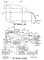
- FIGURE 5 illustrates a typical design approach employing a PROM to replace diode function generator 64.
- the output 35 from difference counter 34 is supplied directly to PROM 90 for the specifying of unique address locations therein.
- the contents of the respective memory location of PROM 90 are selected such that for a given input signal 35 from difference counter 34, a mathematical square root relationship is generated in a digital format as an output 92.
- the output signal 92 is then supplied to digital-to-analog converter 60.
- the output 94 from digital-to-analog converter 60 then represents the desired instantaneous velocity for the head carriage assembly for a given distance from a terminal location according to the desired square root velocity distance relationship.
- Summing means 68 thereafter subtracts the current velocity of the heads relative to the discs, as reported as signal 31 from tachometer 30.
- the resulting error signal 70 represents the amount by which the current velocity must be changed to effect agreement with the desired velocity.
- FIGURE 6(a) illustrates in a tabular form the mapping relation in a PROM between a memory location, i.e., a memory address, and the contents of that address.
- a PROM with sixteen memory locations is used for an example.
- FIGURE 6(a) illustrates the fact that for each of the sixteen individual and unique memory locations (addresses), a corresponding individual and unique value for velocity is stored therein.
- FIGURE 6(b) This relationship between memory locations and the contents stored thereon is illustrated in graphic form in FIGURE 6(b).
- the memory locations i.e., addresses
- the corresponding values stored therein are plotted along the verticle axis.
- the values.illustrated in FIGURE 6(b) are so chosen to approximate a square root relationship 92 between the memory location or adddress which represent distance remaining to be traversed by the head carriage assembly from a current position to a desired terminal position, and the corresponding content of the respective memory location which represents values for the desired velocity of the head carriage assembly according to the square root velocity distance relationship, for each of the respective distances.
- each memory location is converted to a corresponding analog voltage by digital to analog converter 60
- the resulting analog value is a constant value.
- a series of distances are supplied to PROM 90, from difference counter 34, a series of discrete analog voltage steps result as a corresponding output from digital to analog converter 60.
- the signal 31 from tachometer 30 will be a continuous one
- the error signal 70 produced by summing means 68 will be a discontinuous one, i.e., it will have abrupt changes present in its output 70 corresponding to the abrupt changes produced by the discrete differences between successive velocity values.
- error signal 70 is used to control the motion of the head carriage assembly through power amplifier 26 and actuator 24 (FIGURE 1)
- abrupt changes in the output 70 from summing means 68 will produce' abrupt changes in the motion of head carriage assembly 22. This is particulary undesirable as it results in inaccuracies in the positioning of head carraige assembly 22.
- a current solution to this problem includes the integration of the current being supplied to motor actuator 24, and the subsequent subtraction of this value from the velocity level dictated by the PROM.
- This approach is based on the fact the acceleration of actuator 24 is directly proportional to the amount of current flowing in the voice coil of the electric motor used to implement actuator 24. Consequently mathematical integration of the motor current produces a voltage proportional to the resulting velocity of the heads.
- the amount of current flowing through the motor is mathematically integrated by electronic means between each cylinder crossing, and the resulting value subtracted from the constant .numerical value generated by the PROM. This approach can best be understood with reference to FIGURES 7 and 8.
- the output 35 from difference counter 34 is supplied directly to PROM 90 for the specifying of unique address locations therein.
- the contents of the respective memory locations of PROM 90 are selected such that for a given input signal 35 from difference counter 34, a mathematical square root relationship is generated in a digital format as an output 92.
- the output signal 92 is then supplied to digital-to-analog converter 60.
- the output 94 from digital-to-analog . converter 60 then represents the desired instantaneous velocity for the head carriage for a given distance from a terminal location according to the desired square root velocity distance relationship as stored in PROM 90.
- integrator 110 Concurrently, the amount of current being supplied to actuator 24 (FIGURE 1) is integrated by integrator 110.
- the integration process is performed between successive cylinder crossings, as integrator 110 is reset by the signal generated by cylinder detector 32 (FIGURE 1) upon the crossing of each cylinder on servo data disc 12.
- the output 114 from integrator 110 is thereafter subtracted by summing means 112 from the analog output 94 from digital-to-analog converter 60.
- the resulting output 110 from summing means 112 represents the desired velocity for moveable head assembly 22, with the step discontinuities produced by the discrete nature of the output 92 from PROM 90 reduced by the subtraction of the integrated motor current 114.
- the actual velocity of head assembly 22 is thereafter subtracted from output 116 by summing means 68 to produce the desired error signal 70. to drive power amplifier 26 (FIGURE 1).
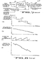
- FIGURE 8(a) illustrates a portion of the distance-velocity. relationships generated by PROM . 90 as curve 120, and the actual desired square root relationship by curve 122.
- FIGURE 8(b) illustrates the corresponding current being supplied to actuator motor 24 (FIGURE 1) from power amplifier 26.
- FIGURE 8(c) illustrates the integration of the motor current illustrated in FIGURE 8(b), and corresponds to output 114 from integrator 110 in FIGURE 7.
- FIGURE 8(d) illustrates the corresponding portion of the velocity command profile, originally illustrated in FIGURE 8(a), after the integration of the motor current is substracted therefrom by summing function 112 (FIGURE 7), and represents the output 116 from summing means 112 (FIGURE 7).
- the current distance between a desired terminal position and a current position is supplied to PROM 90.
- the address specified thereby results in the generation of a corresponding constant level analog voltage by digital-to-analog converter 60, as illustrated by the constant velocity values for discrete groups of distances in FIGURE 8(a).
- the current being supplied to actuator 24 motor (FIGURE 1) is illustrated in FIGURE 8(b), and is integrated by integrator 110 for each discrete group of distances which in practice correspond to cylinder crossings. As the motor current is relatively constant, the integration thereof by integrator 110 produces an output 114 which approximates a linear ramp, as illustrated in FIGURE 8(c).
- the linear ramp produced by integrator 110 is subtracted by summing means 112 from the constant velocity value produced by digital-to-analog converter 60 in response to a discrete velocity value from PROM 90. Consequently, the step discontinuities present in the velocity command profile are reduced, as illustrated in the velocity command profile illustrated in FIGURE 8(d).
- a single constant value for velocity V 101 is specified for the velocity command profile. This results directly from the limitation in the number of memory locations available in the PROM. This limitation has an undesirable effect on the resulting access time for distances of the moveable head assembly greater than d 1 103 from the terminal position do 105, as will be more fully understood by referring to FIGURE 10.
- curve 100 which appears in dashed lines.
- the velocity command profile currently implemented is illustrated by curves 102 and 104 taken together.
- curve 106 illustrates the resulting velocity distance trajectory experienced by the moveable head assembly in traversing the distance to the terminal position d 0 105.
- the moveable head assembly accelerates in an open loop fashion until it attains velocity V 1 101.
- velocity command profile 102 terminates the acceleration of the moveable head assembly when the velocity of V 1 101 is attained, and thereafter operates in a closed loop fashion to maintain the velocity of the moveable head assembly at a velocity of V 1 101 until the moveable head assembly reaches distance d 1 103 from the terminal position d 0 105, i.e., when the constant velocity profile 102 intersects the square root velocity distance deceleration profile . 100.
- the present invention offers a solution to the above described problem by allowing the PROM to be devoted to the terminal portion of the square root velocity distance curve without the attendant requirement of a significant decrease in maximum and mean access times.
- curve 104 illustrates the portion of the velocity command profile implemented with the use of a PROM for distances of the moveable head assembly to the terminal position less than d 1 103.
- Curve 102 illustrates the constant velocity value V 1 101 which was previously specified by the velocity command profile for distances of the moveable head assembly from the terminal position d 105 greater than distance d 1 103.
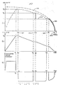
- a velocity command generator incorporating the present invention would, for distances of the moveable head assembly from the terminal position d 0 105 greater than distance d 1 103, specify one or a plurality of additional discrete velocity steps. This is illustrated in FIGURE 11 by the addition of two addition velocity steps whereby a maximum velocity of V 3 is specified by the new velocity command profile for distances greater than d 3 107 of the moveable head assembly from the terminal position of d 0 105. For distances of the moveable head assembly from the terminal position d 0 105 between d 3 107 and d 2 106, the new velocity command profile specifies a maximum velocity of V 2 . For distances of the moveable head assembly from the terminal position d 0 105 between d 2 106 and d 1 103, the new velocity command profile specifies a maximum velocity of the moveable head assembly of V 1 .
- FIGURE 12(a) illustrates a velocity command profile of a velocity command generator incorporating the present invention, as well as the . resulting velocity distance profile of a moveable head assembly in response thereto.
- FIGURE 12(b) and 12(c) illustrate the corresponding actual velocity versus time and current supplied to actuator 22 versus time waveform respectively.
- a positive current is initially applied to actuator 22, as illustrated in FIGURE 12(c).
- the velocity of the moveable head assembly linearly increases as illustrated in FIGURE 12(b), up to time t 1 , i.e., until the velocity of the moveable head assembly reaches velocity V 3 at time t 1 .
- the moveable head assembly consequently accelerates in an open loop fashion until the velocity of the moveale head assembly equals velocity levels V 3 .
- velocity level V 3 is the maximum velocity permitted by the velocoity command generator (FIGURE 12(a))
- V 3 is attained by the moveable head assembly
- closed loop control ensues thereafter.
- the actuator motor current is reduced to zero, and the velocity of the moveable head assembly, in this example, remains essentially equal to V 3 until the moveable head assembly crosses distance d 3 107 whereupon the velocity command profile specifies a new velocity for the moveable head assembly, i.e., velocity level V 2 .
- a deceleration "bang" is produced by the application of a constant negative current to actuator 22, as illustrated in FIGURE 12(c).
- This constant negative current applied to the actuator results in a linear decrease in the velocity of the moveable head assembly, as illustrated in FIGURE 12(b) beginning at time t 2 .
- the negative current is supplied to the actuator until the velocity of the moveable head assembly matches that specified by the velocity command profile, i.e., the velocity of the moveable head assembly reaches velocity level V 2 at time t3, at which point the actuator motor current is again reduced to zero (FIGURE 12(c)).
- This condition continues to exist in this example until the moveable head assembly crosses distance d 2 106 whereupon the velocity command profile specifies a new velocity for the moveable head assembly, i.e., velocity level V,.
- a second deceleration "bang" is produced by the application of a corstant negative current to actuator 22, as illustrated in FIGURE 12(c).
- This constant negative current results in a linear decrease in the velocity of the moveable head assembly, as illustrated in FIGURE 12(b), beginning at time t 4 .
- the negative current is supplied to the actuator until the velocity of the moveable head assembly matches that specified by the velocity command profile, i.e., the velocity of the moveable head assembly reaches velocity level V 1 , at time t 5 , at which point the actuator current is again reduced to zero (FIGURE 12(c)).
- FIGURE 13 An implementation of a velocity command generator incorporating the present invention is illustrated in FIGURE 13.
- fractional crossing detector 140 upon receipt of information from demodulator 28, functions to produce an output 141 for each fractional track which is crossed by the moveable head assembly.
- the number of fractional crossings detected will vary with the particular design of the system incorporating this invention, but in the preferred embodiment was two, i.e., fractional crossing detector 140 would produce an output signal 141 which changes between binary states a multiple number of times for each cylinder track crossed by the moveable head assembly.
- PROM 142 functions to store values for velocity, and in response to the specification of an address, would produce the corresponding digital word stored therein, i.e., the corresponding value for velocity.
- Digital to analog converter 144 functions to convert the binary word supplied to it to a corresponding analog voltage.
- Digital magnitude comparator 146 functions to compare the digital number from difference counter 34 with several predefined numbers, and generates output signals when the number from difference counter 34 is greater than the respective predefined numbers.
- Gain means 148 and 150 function .to provide output signals equal to the input signal multiplied by a predefined amount.
- Switches S 1 and S 2 operate in response to signals from digital magnitude comparator 146 to connect the output signal produced by gain means 148 and 150 respectively to the input of summer 156.
- Summer 156 operates to produce an analog output signal 160 equal to the mathematical sum of the respective inputs thereto.
- the output from summer 156 would represent a desired velocity command profile,' and would be presented as an input to summing means 68.
- Summing means 68 would function to subtract from the desired velocity command profile the signal 31 from tachometer 30 to produce the error signal 70 for power amplifier 26 (FIGURE 1).
- a velocity command generator incorporating the present invention as illustrated in FIGURE 13 operates in the following manner.
- cylinder crossing detector 32 In response to signal 29 produced by demodulator 28 from information from the servo data head, cylinder crossing detector 32 produces -a single pulse in response to each cylinder which is crossed. Concurrently the output from fractional track crossing detector 140 changes state a number of times, two in the preferred embodiment for half track crossing, in response to each cylinder which is crossed.
- Difference counter 34 in response to position command 37 and the signal from cylinder crossing detecter 32 produces a digital word representative of the distance between the current position of the moveable head assembly and the desired terminal position.
- the output from fractional track crossing detector 140 changes state a number of times for each cylinder which is crossed, the output from fractional crossing detector can be considered as the lower order address bits of PROM 142 (least significant bit for half track crossing in the preferred embodiment) in the digital representation of the distance remaining between the current position of the moveable head assembly and the desired terminal position.
- the higher order address bits of the digital representation of the distance remaining between the current position of the moveable head assembly and the desired terminal position are supplied to the digital magnitude comparator 146.
- Digital magnitude comparator functions to compare the digital word presented thereto with predefined constants which represent the distance at which a change is desired in the velocity command profile, e.g., d 107, d 2 106 and d 103 (FIGURE 12(a)).
- the lower order address bits of the digital representation of the distance remaining are supplied as the higher order address inputs to PROM 142.
- the operation of the velocity command generator illustrated in FIGURE 13 can best be understood by way of example. Assuming that the moveable head assembly currently exist at a position corresponding to the intersection of the .distance and velocity axis in FIGURE 12(a) from a desired terminal position d 105. The desired terminal position will be communicated to the velocity command generator by position command 37. Difference counter 34 will, in response to cylinder crossing pulses generated by cylinder crossing detector 32 produce an output which represents the distance remaining between the current position of the moveable head assembly and the desired terminal position.
- the corresponding output from digital magnitude comparator 146 will result in switch S 2 154, S 1 152 to be closed, and the output from PROM 142 to be set to the value V 1 by signal 157. Consequently the inputs to summer 156 are the output from digital to analog converter 144 which is an analog signal representative of velocity value V 1 (FIGURE 12(a)), and the outputs from gain means 148 and 150.
- the gain of gain means 148 is a predefined value which when the value of V I is supplied as an input thereto, produces an output value corresponding to the difference between V 2 and V 1 , e.g., velocity V 2 - V 1 (FIGURE 12(a)).
- the gain of gain means 150 is a predefined value which when the value of V 1 is supplied as an input thereto, produces an output value equal to the difference between V 3 and V 2 , e. g ., V 3 - V 2 , which, when summed with the output of the digital to analog converter 144 and the value produced as an output from gain means 148, produces a output value corresponding to velocity V 3 (FIGURE 12(b)).
- the output from summer 156 will be the sum of the respective inputs thereto, i:e., the output from digital to analog converter 144 and the two gain means 148 and 150, to produce a velocity command profile 160 equal to V 3 (FIGURE 12(a)).
- the output 160 from summer 156 is then applied to summing means 68 which, after subtraction of the current velocity of the moveable head assembly, as reported from tacho- . meter 30, produces a control signal 70 to power amplifier 26, in the manner as previously discussed.
- FIGURE 13 illustrates one implementation of a velocity command generator incorporating the present invention
- the input to gain means 148 and 150 could be supplied directly from a reference voltage rather than from the output of digital to analog converter 144.
- the above discussion has referenced the implementation of a square root velocity distance relationship, it is clear that any curve of interest could be likewise implemented in a similar fashion. Numerous different implementations are in fact possible withjout departing from the spirit and scope of the present inventive concept, which is to be limited only by the following claims.
Landscapes
- Engineering & Computer Science (AREA)
- Human Computer Interaction (AREA)
- Manufacturing & Machinery (AREA)
- Physics & Mathematics (AREA)
- General Physics & Mathematics (AREA)
- Automation & Control Theory (AREA)
- Moving Of Head For Track Selection And Changing (AREA)
- Control Of Position Or Direction (AREA)
Applications Claiming Priority (2)
| Application Number | Priority Date | Filing Date | Title |
|---|---|---|---|
| US41850882A | 1982-09-15 | 1982-09-15 | |
| US418508 | 1982-09-15 |
Publications (2)
| Publication Number | Publication Date |
|---|---|
| EP0103493A1 true EP0103493A1 (de) | 1984-03-21 |
| EP0103493B1 EP0103493B1 (de) | 1987-12-16 |
Family
ID=23658412
Family Applications (1)
| Application Number | Title | Priority Date | Filing Date |
|---|---|---|---|
| EP19830305403 Expired EP0103493B1 (de) | 1982-09-15 | 1983-09-15 | 2-Punkt-gesteuerter Geschwindigkeitsregelgenerator |
Country Status (3)
| Country | Link |
|---|---|
| EP (1) | EP0103493B1 (de) |
| JP (1) | JPS5972526A (de) |
| DE (1) | DE3374967D1 (de) |
Cited By (9)
| Publication number | Priority date | Publication date | Assignee | Title |
|---|---|---|---|---|
| EP0247829A1 (de) * | 1986-05-26 | 1987-12-02 | Pioneer Electronic Corporation | Verfahren und Vorrichtung zur Korrektur der Schleifenverstärkung einer feineinstellbaren Servoschleife |
| EP0226355A3 (en) * | 1985-11-26 | 1988-09-07 | Nippon Telegraph And Telephone Public Corporation | Actuator access control system |
| WO1990010930A1 (en) * | 1989-03-08 | 1990-09-20 | International Business Machines Corporation | Estimator positioning system and method |
| GB2238888A (en) * | 1989-11-15 | 1991-06-12 | Okuma Machinery Works Ltd | Index control apparatus for tool rest of an NC lathe |
| EP0401973A3 (de) * | 1989-05-05 | 1992-02-26 | International Business Machines Corporation | Zuverlässige Spurüberkreuzungsdetektion in einem Datenspeichergerät |
| EP1286237A1 (de) * | 2001-07-20 | 2003-02-26 | Valtronic S.A. | Verfahren zur Steurerung eines Motors |
| KR101273794B1 (ko) * | 2004-09-21 | 2013-06-11 | 3디 시스템즈 인코오퍼레이티드 | 3d 프린터를 보수하기 위한 장치 및 방법 |
| EP2757427A4 (de) * | 2011-09-16 | 2016-05-18 | Isuzu Motors Ltd | Verfahren und stellgliedsteuerung |
| US9558897B2 (en) | 2011-07-12 | 2017-01-31 | Isuzu Motors Limited | Actuator control method and actuator control device |
Families Citing this family (5)
| Publication number | Priority date | Publication date | Assignee | Title |
|---|---|---|---|---|
| US4675761A (en) * | 1986-03-03 | 1987-06-23 | International Business Machines Corporation | Magnetic head positioning apparatus and method |
| JPS62270073A (ja) * | 1986-05-19 | 1987-11-24 | Sanyo Electric Co Ltd | 光学的記録再生装置 |
| JPH051801Y2 (de) * | 1986-08-29 | 1993-01-18 | ||
| JP2518885B2 (ja) * | 1988-02-05 | 1996-07-31 | シャープ株式会社 | アクセス制御方式 |
| JPH0323570A (ja) * | 1989-06-20 | 1991-01-31 | Tokico Ltd | 磁気ディスク装置 |
Citations (5)
| Publication number | Priority date | Publication date | Assignee | Title |
|---|---|---|---|---|
| EP0007449A1 (de) * | 1978-07-31 | 1980-02-06 | Siemens Aktiengesellschaft | Verfahren zum Erzeugen von digitalen Ist-Geschwindigkeitssignalen in einem Positioniersystem für die Schreib-/Leseköpfe eines Magnetplattenspeichers |
| EP0007638A1 (de) * | 1978-07-31 | 1980-02-06 | Siemens Aktiengesellschaft | Einrichtung zum Regeln der Geschwindigkeit eines Positionierers für die Schreib-/Leseköpfe eines Magnetplattenspeichers |
| US4239942A (en) * | 1978-08-22 | 1980-12-16 | U.S. Philips Corporation | Dual radial position servo to compensate for radial tracking failure in an optical disc player |
| EP0063936A1 (de) * | 1981-04-24 | 1982-11-03 | Iomega Corporation | Anordnung zur Lageregelung |
| EP0069549A1 (de) * | 1981-07-02 | 1983-01-12 | Irwin International, Inc. | Verfahren zur Positionierung eines Umwandlers über einer Platte |
Family Cites Families (2)
| Publication number | Priority date | Publication date | Assignee | Title |
|---|---|---|---|---|
| JPS5734210A (en) * | 1980-08-05 | 1982-02-24 | Toshiba Corp | Positioning apparatus |
| JPS5734209A (en) * | 1980-08-05 | 1982-02-24 | Toshiba Corp | Positioning apparatus |
-
1983
- 1983-09-15 EP EP19830305403 patent/EP0103493B1/de not_active Expired
- 1983-09-15 DE DE8383305403T patent/DE3374967D1/de not_active Expired
- 1983-09-16 JP JP17104883A patent/JPS5972526A/ja active Pending
Patent Citations (5)
| Publication number | Priority date | Publication date | Assignee | Title |
|---|---|---|---|---|
| EP0007449A1 (de) * | 1978-07-31 | 1980-02-06 | Siemens Aktiengesellschaft | Verfahren zum Erzeugen von digitalen Ist-Geschwindigkeitssignalen in einem Positioniersystem für die Schreib-/Leseköpfe eines Magnetplattenspeichers |
| EP0007638A1 (de) * | 1978-07-31 | 1980-02-06 | Siemens Aktiengesellschaft | Einrichtung zum Regeln der Geschwindigkeit eines Positionierers für die Schreib-/Leseköpfe eines Magnetplattenspeichers |
| US4239942A (en) * | 1978-08-22 | 1980-12-16 | U.S. Philips Corporation | Dual radial position servo to compensate for radial tracking failure in an optical disc player |
| EP0063936A1 (de) * | 1981-04-24 | 1982-11-03 | Iomega Corporation | Anordnung zur Lageregelung |
| EP0069549A1 (de) * | 1981-07-02 | 1983-01-12 | Irwin International, Inc. | Verfahren zur Positionierung eines Umwandlers über einer Platte |
Cited By (13)
| Publication number | Priority date | Publication date | Assignee | Title |
|---|---|---|---|---|
| EP0226355A3 (en) * | 1985-11-26 | 1988-09-07 | Nippon Telegraph And Telephone Public Corporation | Actuator access control system |
| EP0247829A1 (de) * | 1986-05-26 | 1987-12-02 | Pioneer Electronic Corporation | Verfahren und Vorrichtung zur Korrektur der Schleifenverstärkung einer feineinstellbaren Servoschleife |
| US5182684A (en) * | 1989-03-08 | 1993-01-26 | International Business Machines Corporation | Estimator positioning system and method |
| WO1990010930A1 (en) * | 1989-03-08 | 1990-09-20 | International Business Machines Corporation | Estimator positioning system and method |
| EP0401973A3 (de) * | 1989-05-05 | 1992-02-26 | International Business Machines Corporation | Zuverlässige Spurüberkreuzungsdetektion in einem Datenspeichergerät |
| GB2238888A (en) * | 1989-11-15 | 1991-06-12 | Okuma Machinery Works Ltd | Index control apparatus for tool rest of an NC lathe |
| US5121039A (en) * | 1989-11-15 | 1992-06-09 | Okuma Machinery Works | Index control apparatus for tool rest of nc lathe |
| GB2238888B (en) * | 1989-11-15 | 1994-05-04 | Okuma Machinery Works Ltd | Index control apparatus for tool rest of an NC lathe |
| EP1286237A1 (de) * | 2001-07-20 | 2003-02-26 | Valtronic S.A. | Verfahren zur Steurerung eines Motors |
| KR101273794B1 (ko) * | 2004-09-21 | 2013-06-11 | 3디 시스템즈 인코오퍼레이티드 | 3d 프린터를 보수하기 위한 장치 및 방법 |
| US9558897B2 (en) | 2011-07-12 | 2017-01-31 | Isuzu Motors Limited | Actuator control method and actuator control device |
| EP2757427A4 (de) * | 2011-09-16 | 2016-05-18 | Isuzu Motors Ltd | Verfahren und stellgliedsteuerung |
| US9519275B2 (en) | 2011-09-16 | 2016-12-13 | Isuzu Motors Limited | Actuator control method and actuator control device |
Also Published As
| Publication number | Publication date |
|---|---|
| JPS5972526A (ja) | 1984-04-24 |
| EP0103493B1 (de) | 1987-12-16 |
| DE3374967D1 (en) | 1988-01-28 |
Similar Documents
| Publication | Publication Date | Title |
|---|---|---|
| US4638230A (en) | Bang-bang controlled velocity command generator | |
| US4535372A (en) | Position tracking servo control systems and methods | |
| US4217612A (en) | Servo system for track accessing and track following in a disk drive | |
| US4103314A (en) | Motion control system | |
| EP0003070B1 (de) | Zeitoptimale digitale Steuerung zum Positionieren unter Verwendung eines Modells der Vorrichtung | |
| US3699555A (en) | Apparatus for rapid action displacement control | |
| EP0103493A1 (de) | 2-Punkt-gesteuerter Geschwindigkeitsregelgenerator | |
| EP0002133B1 (de) | Servomechanisches Positioniersystem | |
| EP0013326B1 (de) | Servo-Lageregelungssystem mit abgetasteten Positionswerten und seine Anwendung in einem Plattenspeicher mit Servo-Sektoren | |
| EP0000261B1 (de) | Schaltung zur direkten und rückgekoppelten Steuerung einer Positioniereinrichtung | |
| US4924160A (en) | Staggered seeking method for disk drive sector servo | |
| KR0124052B1 (ko) | 고성능 디스크 드라이브, 이 디스크 드라이브내의 서보 섹터 패턴 및 이 디스크 드라이브에서 데이타 변환기 헤드의 위치를 결정하는 방법 | |
| US4816941A (en) | Disk file digital servo control system with optimized sampling rate | |
| US4031443A (en) | Apparatus for positionally controlling a movable head assembly | |
| US6594105B1 (en) | Time optimal seeks using linear velocity scheduling | |
| US4168457A (en) | Self adaptive speed control system | |
| US4980876A (en) | Single stage track seek method | |
| JPH0449187B2 (de) | ||
| US4700244A (en) | Process and system for compensating for information shifts on disc storage media | |
| US4786990A (en) | Servo gain compensation in a disc drive | |
| US5659438A (en) | Head positioning control system using stored voice coil motor correction data | |
| US5233486A (en) | Method for correcting track counting errors during seeks in a hard disc drive | |
| JPS63867B2 (de) | ||
| US5329409A (en) | Correction of current feedback offset for disc drive servo systems | |
| US4812929A (en) | Head positioning mechanism for rotating disk data storage system |
Legal Events
| Date | Code | Title | Description |
|---|---|---|---|
| PUAI | Public reference made under article 153(3) epc to a published international application that has entered the european phase |
Free format text: ORIGINAL CODE: 0009012 |
|
| AK | Designated contracting states |
Designated state(s): DE FR GB IT NL SE |
|
| 17P | Request for examination filed |
Effective date: 19840908 |
|
| 17Q | First examination report despatched |
Effective date: 19860117 |
|
| ITF | It: translation for a ep patent filed | ||
| GRAA | (expected) grant |
Free format text: ORIGINAL CODE: 0009210 |
|
| AK | Designated contracting states |
Kind code of ref document: B1 Designated state(s): DE FR GB IT NL SE |
|
| REF | Corresponds to: |
Ref document number: 3374967 Country of ref document: DE Date of ref document: 19880128 |
|
| ET | Fr: translation filed | ||
| PLBE | No opposition filed within time limit |
Free format text: ORIGINAL CODE: 0009261 |
|
| STAA | Information on the status of an ep patent application or granted ep patent |
Free format text: STATUS: NO OPPOSITION FILED WITHIN TIME LIMIT |
|
| 26N | No opposition filed | ||
| PG25 | Lapsed in a contracting state [announced via postgrant information from national office to epo] |
Ref country code: GB Effective date: 19890915 |
|
| PG25 | Lapsed in a contracting state [announced via postgrant information from national office to epo] |
Ref country code: SE Effective date: 19890916 |
|
| PG25 | Lapsed in a contracting state [announced via postgrant information from national office to epo] |
Ref country code: NL Effective date: 19900401 |
|
| GBPC | Gb: european patent ceased through non-payment of renewal fee | ||
| NLV4 | Nl: lapsed or anulled due to non-payment of the annual fee | ||
| PG25 | Lapsed in a contracting state [announced via postgrant information from national office to epo] |
Ref country code: FR Effective date: 19900531 |
|
| PG25 | Lapsed in a contracting state [announced via postgrant information from national office to epo] |
Ref country code: DE Effective date: 19900601 |
|
| REG | Reference to a national code |
Ref country code: FR Ref legal event code: ST |
|
| EUG | Se: european patent has lapsed |
Ref document number: 83305403.4 Effective date: 19900521 |