EP0103493B1 - 2-Punkt-gesteuerter Geschwindigkeitsregelgenerator - Google Patents
2-Punkt-gesteuerter Geschwindigkeitsregelgenerator Download PDFInfo
- Publication number
- EP0103493B1 EP0103493B1 EP19830305403 EP83305403A EP0103493B1 EP 0103493 B1 EP0103493 B1 EP 0103493B1 EP 19830305403 EP19830305403 EP 19830305403 EP 83305403 A EP83305403 A EP 83305403A EP 0103493 B1 EP0103493 B1 EP 0103493B1
- Authority
- EP
- European Patent Office
- Prior art keywords
- velocity
- terminal position
- value
- distance
- signal
- Prior art date
- Legal status (The legal status is an assumption and is not a legal conclusion. Google has not performed a legal analysis and makes no representation as to the accuracy of the status listed.)
- Expired
Links
Images
Classifications
-
- G—PHYSICS
- G11—INFORMATION STORAGE
- G11B—INFORMATION STORAGE BASED ON RELATIVE MOVEMENT BETWEEN RECORD CARRIER AND TRANSDUCER
- G11B5/00—Recording by magnetisation or demagnetisation of a record carrier; Reproducing by magnetic means; Record carriers therefor
- G11B5/48—Disposition or mounting of heads or head supports relative to record carriers ; arrangements of heads, e.g. for scanning the record carrier to increase the relative speed
- G11B5/54—Disposition or mounting of heads or head supports relative to record carriers ; arrangements of heads, e.g. for scanning the record carrier to increase the relative speed with provision for moving the head into or out of its operative position or across tracks
- G11B5/55—Track change, selection or acquisition by displacement of the head
- G11B5/5521—Track change, selection or acquisition by displacement of the head across disk tracks
- G11B5/5552—Track change, selection or acquisition by displacement of the head across disk tracks using fine positioning means for track acquisition separate from the coarse (e.g. track changing) positioning means
-
- G—PHYSICS
- G05—CONTROLLING; REGULATING
- G05B—CONTROL OR REGULATING SYSTEMS IN GENERAL; FUNCTIONAL ELEMENTS OF SUCH SYSTEMS; MONITORING OR TESTING ARRANGEMENTS FOR SUCH SYSTEMS OR ELEMENTS
- G05B19/00—Program-control systems
- G05B19/02—Program-control systems electric
- G05B19/18—Numerical control [NC], i.e. automatically operating machines, in particular machine tools, e.g. in a manufacturing environment, so as to execute positioning, movement or co-ordinated operations by means of program data in numerical form
- G05B19/19—Numerical control [NC], i.e. automatically operating machines, in particular machine tools, e.g. in a manufacturing environment, so as to execute positioning, movement or co-ordinated operations by means of program data in numerical form characterised by positioning or contouring control systems, e.g. to control position from one programmed point to another or to control movement along a programmed continuous path
- G05B19/21—Numerical control [NC], i.e. automatically operating machines, in particular machine tools, e.g. in a manufacturing environment, so as to execute positioning, movement or co-ordinated operations by means of program data in numerical form characterised by positioning or contouring control systems, e.g. to control position from one programmed point to another or to control movement along a programmed continuous path using an incremental digital measuring device
- G05B19/23—Numerical control [NC], i.e. automatically operating machines, in particular machine tools, e.g. in a manufacturing environment, so as to execute positioning, movement or co-ordinated operations by means of program data in numerical form characterised by positioning or contouring control systems, e.g. to control position from one programmed point to another or to control movement along a programmed continuous path using an incremental digital measuring device for point-to-point control
- G05B19/231—Numerical control [NC], i.e. automatically operating machines, in particular machine tools, e.g. in a manufacturing environment, so as to execute positioning, movement or co-ordinated operations by means of program data in numerical form characterised by positioning or contouring control systems, e.g. to control position from one programmed point to another or to control movement along a programmed continuous path using an incremental digital measuring device for point-to-point control the positional error is used to control continuously the servomotor according to its magnitude
- G05B19/237—Numerical control [NC], i.e. automatically operating machines, in particular machine tools, e.g. in a manufacturing environment, so as to execute positioning, movement or co-ordinated operations by means of program data in numerical form characterised by positioning or contouring control systems, e.g. to control position from one programmed point to another or to control movement along a programmed continuous path using an incremental digital measuring device for point-to-point control the positional error is used to control continuously the servomotor according to its magnitude with a combination of feedback covered by G05B19/232 - G05B19/235
-
- G—PHYSICS
- G05—CONTROLLING; REGULATING
- G05B—CONTROL OR REGULATING SYSTEMS IN GENERAL; FUNCTIONAL ELEMENTS OF SUCH SYSTEMS; MONITORING OR TESTING ARRANGEMENTS FOR SUCH SYSTEMS OR ELEMENTS
- G05B2219/00—Program-control systems
- G05B2219/30—Nc systems
- G05B2219/41—Servomotor, servo controller till figures
- G05B2219/41086—Bang bang control
Definitions
- This invention relates generally to magnetic disc data storage devices and more particularly to an improved method for the accurate generation of a velocity command profile for the positioning of transducer apparatus relative to a storage medium.
- a disc drive typically comprises a disc pack consisting of a plurality of magnetic discs mounted on a common drive spindle.
- the disc drive further comprises an array of magnetic heads disposed in read/write relation with the discs.
- the heads are mounted on an actuator driven carriage mechanism, at least one head being operatively associated with each magnetic surface. In such drives the heads are usually moved substantially radially across the discs to access a desired track on any disc.
- Information is stored on a surface of a disc by being recorded thereon in a serial format in concentric rings or tracks known in the art as cylinders.
- the concentric cylinders are arranged across the surface of a disc with varying radii.
- the density at which cylinders are placed on a disc vary greatly, from twenty-four tracks per centimetre to more than four hundred tracks per centimetre, depending upon the parameters of a . particular system.
- a transducer, or read and write transducer assembly of a movable head drive ccoperates with a particular concentric track on a rotating disc as long as the head retains a selected position. That position of the head is also defined as a particular radial position of the transducer(s) therein, relative to the disc's axis. For a change of tracks, the head has to be displaced radially to that axis so that the transducer(s) may lock on another track. In order to minimize the time required to access information on any particular track, the head must be moved as rapidly as possible from its present position to the desired position, for cooperation with the desired track.
- a rapid displacement of this kind requires the head to be first accelerated as long as possible, and thereafter to be declerated and stopped directly on the new position. Moreover, it is desirable to have the displacement control operation merged in a tracking operation that maintains the transducer and the head assembly in the desired position.
- All disc. memories have or are characterised by minimum, average and maximum access times.
- Mimimum access time is the time for one track seek.
- Maximum access time is the time needed for travelling the maximum seek length.
- Average access time is the average time needed for any seek length and is equal to the total accumulated seek time for a large number of seeks divided by the total number of seeks.
- the disc drive is characterised by a "mean access time” instead.
- Mean access time is the time required by the heads, which read from or write upon the magnetic disc, to move from an outside track on the disc and gain access to a data item contained on the central track. The time is measured from the moment the heads receive an order from the processing system to seek a data item.
- the central track of the disc has a serial number equal to the mean of the outside track serial numbers. For example, if there are two hundred recording tracks numbered from 0 to 200, then the central track is track 100.
- the mean access time is determined primarily by two factors. One is the average time taken by the disc to complete one revolution. The second is the average time taken by the magnetic heads to move from the outside track to the central track.
- the preferred approach is to reduce the average time necessary to move the magnetic head by improving the head control apparatus.
- Head control apparatus usually includes a "voice coil” electrodynamic motor.
- the motor has a coil which moves linearly within a permanent magnet, defining a cylindrical core.
- the coil is mechanically linked to a carriage which carries the magnetic heads.
- the carriage moves along two parallel rails.
- the coil, carriage and magnetic heads, in combination, constitute a movable head assembly.
- the current supplied to the voice coil is controlled for obtaining a desired velocity profile of the moveable head assembly. Acceleration and deceleration phases are controlled based upon distance still to be travelled and in relation to the actual velocity in any instant; the moving assembly stops in the desired position with the required degree of accuracy by operation of a velocity command signal that reduces to zero as the object approaches the desired position.
- the drive system i.e. the actuators for the magnetic head to provide constant acceleration up to a peak velocity (Vp) and thereafter to control the drive system in accordance with a velocity profile defining the desired velocity of the movable member in terms of its distance from its intended terminal position.
- the velocity profile is usually parabolic and it has been proposed to employ a diode function generator for the generation of the velocity profile. Such a generator is, however, not very accurate.
- a programmable read-only memory (PROM) to store, at addresses corresponding to discrete distances of the member from the terminal position, respective velocity values according to the desired (parabolic) profile.
- PROM programmable read-only memory
- the present invention offers a solution to the above-described problem by allowing the PROM to be devoted to the terminal portion of the square root velocity distance curve without the attendant consequence of a significant decrease in maximum and mean access times.
- EP-0007449-A1 It is known from EP-0007449-A1 to provide a velocity profile generator for use in controlling the movement of a movable member from an initial position towards a terminal position, the generator including means (a track difference register) for producing a signal representing the distance of the member away from the terminal position.
- the track difference register controls a read-only memory to generate digital values defining the velocity profile.
- the velocity profile generator is characterised by means for comparing the signal with predefined distances to provide an indication of the distance as within one of a plurality of ranges of distance, means providing a signal of predetermined value and representing a selected velocity for one of said ranges and means responsive to the indication of range to augment the predetermined value whereby to generate a pre-selected velocity value for the range of distances embracing the actual distance of the member from the terminal position.
- the signal representing the distance of the member away from the terminal position is in digital form and means providing the signal of predetermined value responds to a digital value representing the lower limit of the lowest range of distances.
- the velocity profile is generated by a digital data store which is addressed according to the signal representing distance away from the terminal position to provide a respective velocity value from a set of stored velocity values.
- the digital data store may also provide the said signal of predetermined value.
- EP-0007449-A1 also describes apparatus for controlling the movement of a movable member towards a terminal position, the apparatus comprising means for producing a signal representing the actual distance of the member from the terminal position, drive means for the member and means for detecting the actual velocity of the member.
- such apparatus is characterised by means for comparing the said signal with defined distances and for providing, for each of a plurality of consecutive ranges of distance of the member from the terminal position, a respective selected velocity value and a control arrangement which for each range causes the application of predetermined energisation to the drive means to reduce the velocity of the member to the selected value associated with the range.
- the energisation of the drive means is substantially constant while the velocity of the member is being reduced in any of the said ranges and is reduced to allow the member to maintain the respective selected value of velocity for any remaining part of the range.
- the present invention provides for improved access time and greater accuracy in the digital synthesis of the velocity/distance relationship by providing for the generation of a plurality of additional discrete velocity steps for distances whose corresponding velocity values were in prior practice defined by a single constant velocity value.
- the digital storage means can be restricted to storing the desired velocity/distance relation for the terminal portion of the velocity distance curve with the desired accuracy. A plurality of discrete velocity steps is then generated for distances whose corresponding values for velocity are not stored in the PROM.
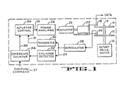
- a disc drive comprises a pair of magnetically coated recording discs 10 and 12 each having a multiplicity of concentrically disposed data recording tracks and being mounted on a shaft 14 which is driven by a rotary drive motor 16.
- Magnetic read/write heads 18 and 20 are operatively associated with discs 10 and 12 respectively.
- a movable head assembly 22 on which the heads are mounted is moved radially across the discs by an actuator 24 to position the heads over particular data tracks.
- the actuator 24 may be a voice coil electrodynamic motor, and is energised by a power amplifier 26 to move and stop the movable head assembly.
- the disc 12 has recorded thereon patterns of information in concentric rings which are used exclusively in connection with head 20 and the associated positioning apparatus to accurately position the head 18 over a desired cylinder of information; the head 20 and the disc 12 are usually called a 'servo data head' and a 'servo data disc' respectively.
- a typical disc drive usually comprises a plurality of data discs (10) and associated heads (18), arranged in a stack on shaft 14 such that corresponding data tracks of all the data discs are disposed one above the other in cylindrical fashion.
- servo data detected by head 20 is applied to a demodulator 28, which produces a waveform which varies from a minimum value to a maximum value as the head 20 passes over each of the concentric servo data tracks on the disc 12. Consequently the waveform produced by demodulator 28 is representative of linear displacement of the movable head assembly 22, and is applied to a tachometer 30 and a cylinder detector 32.
- the cylinder detector 32 produces a single pulse for each track or cylinder of servo data which head 20 crosses as the carriage 22 moves the heads 18 and 20 radially across the surfaces of discs 10 and 12.
- the pulses so produced by cylinder detector 32 are supplied to a difference counter 34 which keeps track of the location of heads 18 and 20 relative to the cylinders of recorded information on discs 10 and 12 by counting the number of cylinder crossings detected by the head 20 as it moves across the servo data disc 12.
- Difference counter 24 also receives a position command 37 from an external control system which indicates the desired cylinder over which head 18 is to be positioned for the recording or playback of information. Difference counter 34 thereafter supplies the necessary signal 35 to an actuator control 36 for the subsequent repositioning of movable head assembly 22.
- Actuator control 36 also receives from tachometer 30 a signal 31 which indicates the actual velocity and direction at which movable head assembly 22 and consequently heads 18 and 20 are currently moving. Based on signals supplied from tachometer 30 and difference counter 34, actuator control 36 generates the necessary command signal for power amplifier 26 to drive actuator 24 to position the head 18 over the desired cylinder on disc 10 in the minimum time.
- This present invention includes an improved method for the implementation of actuator control 36.
- Actuator control. 36 is designed so that movable head assembly 22 traverses the respective distances in minimum time. This is achieved by controlling the voice coil current in the electric motor used to implement actuator 24 to obtain a particular velocity profile.
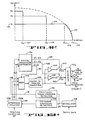
- curve 104 illustrates . the portion of the velocity command profile implemented with the use of a PROM for distances of the movable head assembly to the terminal position less than d, (103).
- Curve 102 illustrates the constant velocity value V, (101) which was previously specified by the velocity command profile for distances of the movable head assembly from the terminal position do (105) greater than distance d, (103).
- a velocity command generator incorporating the present invention would, for distances of the movable head assembly from the terminal position do (105) greater then distance d, (103), specify at least one additional discrete velocity step. This is illustrated in Figure 2 by the addition of two velocity steps whereby a maximum velocity of V 3 is specified by the new velocity command profile for distances greater than d 3 (107) of the movable head assembly from the terminal position of do. For distances of the movable head assembly from the terminal position do between d 3 and d 2 , the new velocity command profile specifies a maximum velocity of V 2 . For distances of the movable head assembly from the terminal position do between d 2 and d l , the new velocity command profile specifies a maximum velocity of the movable head assembly of V,..
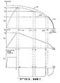
- FIG. 3(a) illustrates a velocity command profile of a velocity command generator incorporating the present invention, as well as the resulting velocity/distance profile of a movable head assembly in response thereto.
- Figures 3(b) and 3(c) illustrate the corresponding actual velocity versus time and the current supplied to actuator 22 versus time respectively.
- a positive current is initially applied to actuator 22, as illustrated in Figure 3(c).
- the velocity of the movable head assembly linearly increases as illustrated in Figure 3(b), up to time t 1 , i.e., until the velocity of the movable head assembly reaches velocity V 3 at time t 1 .
- the movable head assembly consquently accelerates in an open loop fashion until the velocity of the movable head assembly equals velocity level V 3 .
- velocity level V 3 is the maximum velocity permitted by the velocity command generator, once velocity V 3 is attained by the movable head assembly, closed loop control ensues thereafter.
- the actuator motor current is reduced to zero, and the velocity of the movable head assembly, in this example, remains essentially equal to V 3 until the movable head assembly crosses distance d 3 whereupon the velocity command profile specifies a new velocity for the movable head assembly, i.e. velocity level V 2 .
- a deceleration "bang" is produced by the application of a constant negative current to actuator 22, as illustrated in Figure 3(c).
- This constant negative current applied to the actuator results in a linear decrease in the velocity of the movable head assembly, as illustrated in Figure 3(b) beginning at time t 2 .
- the negative current is supplied to the actuator until the velocity of the movable head assembly matches that specified by the velocity command profile, i.e., the velocity of the movable head assembly reaches velocity level V 2 at time t 3 , at which point the actuator motor current is again reduced to zero, as shown in Figure 3(c).
- This condition continues to exist in this example until the movable head assembly crosses distance d 2 whereupon the velocity command profile specifies a new velocity for the movable head assembly, i.e., velocity level V 1 .
- a second deceleration "bang" is produced by the application of a constant negative current to actuator 22, as illustrated in Figure 3(c).
- This constant negative current results in a linear decrease in the velocity of the movable head assembly, as illustrated in Figure 3(b), beginning at time t 4 .
- the negative current is supplied to the actuator until the velocity of the movable head assembly matches that specified by the velocity command profile, i.e., the velocity of the movable head assembly reaches velocity level V,, at time t s , at which point the actuator current is again reduced to zero.
- a fractional crossing detector 140 upon receipt of information from demodulator 28, functions to produce an output 141 for each fractional track which is crossed by the movable head assembly.
- the number of fractional crossings detected will vary with the particular design of the system incorporating this invention, but in the preferred embodiment was two, i.e., fractional crossing detector 140 would produce an output signal 141 which changes between binary states twice for each cylinder track crossed by the movable head assembly.
- PROM 142 functions to store values for velocity, and in response to the specification of an address, would produce the corresponding digital word stored therein, i.e., the corresponding value for velocity.
- Digital to analog converter 144 functions to convert the binary word supplied to it to a corresponding analog voltage.
- Digital magnitude comparator 146 functions to compare the digital number from difference counter 34 with several predefined numbers, and generates output signals when the number from difference counter 34 is greater than the respective predefined numbers.
- Amplifiers 148 and 150 function to provide output signals equal to the input signal multiplied by a predefined amount.
- Switches S 1 and S 2 operate in response to signals from digital magnitude comparator 146 to connect the output signal produced by amplifiers 148 and 150 respectively to the input of summer 156.
- Summer 156 operates to produce an analog output signal 160 equal to the mathematical sum of the respective inputs thereto.
- the output from summer 156 would represent a desired velocity command profile, and would be presented as an input to summing means 68.
- Summing means 68 would function to subtract from the desired velocity command profile the signal 31 from tachometer 30 to produce the error signal 70 for power amplifier 26 ( Figure 1).
- a velocity command generator incorporating the present invention as illustrated in Figure 4 operates in the following manner.
- cylinder crossing detector 32 In response to signal 29 produced by demodulator 28 from information from the servo data head, cylinder crossing detector 32 produces a single pulse in response to each cylinder which is crossed. Concurrently the output from fractional track crossing detector 140 changes state a number of times, in response to each track which is crossed.
- Difference counter 34 in response to position command 37 and the signal from cylinder crossing detector 32, produces a digital word representative of the distance between the current position of the movable head assembly and the desired terminal position.
- the output from fractional track crossing detector 140 changes state a number of times for each cylinder which is crossed, the output from factional crossing detector can be considered as the lower order address bits of PROM 142 (least significant bit for half track crossing in the preferred embodiment) in the digital representation of the distance remaining between the actual position of the movable head assembly and the desired terminal position.
- the digital magnitude comparator 146 Digital magnitude comparator functions to compare the digital word presented thereto with predefined constants which represent the distances at which a change is desired in the velocity command profile, e.g., d 3 , d 2 and d 1 .
- the lower order address bits of the digital representation of the distance remaining are supplied as the higher order address inputs to PROM 142.
- the operation of the velocity command generator illustrated in Figure 4 can best be understood way of example. Assume that the movable head assembly is located at a position corresponding to the intersection of the distance and velocity axis in Figure 3(a) from a desired terminal position do. The desired terminal position will be communicated to the velocity command generator by position command 37. Difference counter 34 will, in response to cylinder crossing pulses generated by cylinder crossing detector 32 produce an output which represents the distance remaining between the current position of the movable head assembly and desired terminal position.
- the corresponding output from digital magnitude comparator 146 will cause switches S 2 (154) and S 1 (152) to be closed; the output from PROM 142 will be set to the value V 1 by signal 157. Consequently the inputs to summer 156 are the output from digital to analog converter 144, i.e. an analog signal representative of velocity value V 1 , and the outputs from amplifiers 148 and 150.
- the gain of amplifier 148 is a predefined value which when the value of V 1 is supplied as an input thereto, produces an output value corresponding to the difference between V 2 and V 1 , e.g., velocity V 2 -V 1 .
- the gain of amplifier 150 is such that when the value of V 1 is supplied as an input thereto, the amplifier 150 produces an output value equal to the difference between V 3 and V 2 , e.g., V 3 -V 2 , which, when summed with the output of the digital to analog converter 144 and the value produced as an output from amplifier 148, produces an output value corresponding to velocity V 3 . Consequently in the present example, with the position of the head carriage assembly at the intersection of the distance and velocity axis in Figure 3(a), the output from summer 156 will be the sum of the respective inputs thereto, i.e., the output from digital to analog converter 144 and the two amplifiers 148 and 150, to produce a velocity command 160 equal to V 3 .
- the output 160 from summer 156 is then applied to summing means 68 which, after subtraction of the current velocity of the movable head assembly, as reported from tachometer 30, produces a control signal 70 to power amplifier 26, in the manner as previously discussed.
- the signal 159 from digital magnitude comparator 146 will cause switch S 2 to open, disconnecting amplifier 150 from the corresponding input to summer 156.
- the summer 156 will have as an input thereto the output from digital to analog converter 144, which because the distance of the movable head assembly for the desired terminal position is still greater than d l , will produce an analog signal equal to velocity V i .
- signal 158 from digital magnitude comparator 146 will cause switch S, to be closed. Consequently the analog voltage 160 produced by summer 156 will be a value corresponding to velocity V 2 .
- Figure 4 illustrates one implementation of a velocity command generator incorporating the present invention
- the input to amplifiers 148 and 150 could be supplied directly from a reference voltage rather than from the output of digital to analog converter 144.
- the above discussion is based on the implementation of a square root velocity distance relationship, it is clear that any curve of interest could be implemented in a similar fashion.
Landscapes
- Engineering & Computer Science (AREA)
- Human Computer Interaction (AREA)
- Manufacturing & Machinery (AREA)
- Physics & Mathematics (AREA)
- General Physics & Mathematics (AREA)
- Automation & Control Theory (AREA)
- Moving Of Head For Track Selection And Changing (AREA)
- Control Of Position Or Direction (AREA)
Claims (7)
Applications Claiming Priority (2)
| Application Number | Priority Date | Filing Date | Title |
|---|---|---|---|
| US41850882A | 1982-09-15 | 1982-09-15 | |
| US418508 | 1982-09-15 |
Publications (2)
| Publication Number | Publication Date |
|---|---|
| EP0103493A1 EP0103493A1 (de) | 1984-03-21 |
| EP0103493B1 true EP0103493B1 (de) | 1987-12-16 |
Family
ID=23658412
Family Applications (1)
| Application Number | Title | Priority Date | Filing Date |
|---|---|---|---|
| EP19830305403 Expired EP0103493B1 (de) | 1982-09-15 | 1983-09-15 | 2-Punkt-gesteuerter Geschwindigkeitsregelgenerator |
Country Status (3)
| Country | Link |
|---|---|
| EP (1) | EP0103493B1 (de) |
| JP (1) | JPS5972526A (de) |
| DE (1) | DE3374967D1 (de) |
Cited By (1)
| Publication number | Priority date | Publication date | Assignee | Title |
|---|---|---|---|---|
| DE4019657A1 (de) * | 1989-06-20 | 1991-01-10 | Tokico Ltd | Magnetplattenspeichervorrichtung |
Families Citing this family (13)
| Publication number | Priority date | Publication date | Assignee | Title |
|---|---|---|---|---|
| JPH0833771B2 (ja) * | 1985-11-26 | 1996-03-29 | 日本電信電話株式会社 | アクチユエ−タのアクセス制御方法 |
| US4675761A (en) * | 1986-03-03 | 1987-06-23 | International Business Machines Corporation | Magnetic head positioning apparatus and method |
| JPS62270073A (ja) * | 1986-05-19 | 1987-11-24 | Sanyo Electric Co Ltd | 光学的記録再生装置 |
| US4878211A (en) * | 1986-05-26 | 1989-10-31 | Pioneer Electronic Corporation | Method and apparatus for correcting the loop gain of a servo loop in accordance with measurements during open-loop operation |
| JPH051801Y2 (de) * | 1986-08-29 | 1993-01-18 | ||
| JP2518885B2 (ja) * | 1988-02-05 | 1996-07-31 | シャープ株式会社 | アクセス制御方式 |
| WO1990010930A1 (en) * | 1989-03-08 | 1990-09-20 | International Business Machines Corporation | Estimator positioning system and method |
| US5038333A (en) * | 1989-05-05 | 1991-08-06 | International Business Machines Corporation | Positioning systems including reliable track crossing detection for high speed relative motions |
| JPH03161248A (ja) * | 1989-11-15 | 1991-07-11 | Okuma Mach Works Ltd | Nc旋盤用刃物台の割出し制御装置 |
| EP1286237A1 (de) * | 2001-07-20 | 2003-02-26 | Valtronic S.A. | Verfahren zur Steurerung eines Motors |
| US7387359B2 (en) * | 2004-09-21 | 2008-06-17 | Z Corporation | Apparatus and methods for servicing 3D printers |
| JP5803361B2 (ja) | 2011-07-12 | 2015-11-04 | いすゞ自動車株式会社 | アクチュエータの制御方法及びアクチュエータの制御装置 |
| JP5838681B2 (ja) * | 2011-09-16 | 2016-01-06 | いすゞ自動車株式会社 | アクチュエータの制御方法及びアクチュエータの制御装置 |
Family Cites Families (7)
| Publication number | Priority date | Publication date | Assignee | Title |
|---|---|---|---|---|
| DE2833591A1 (de) * | 1978-07-31 | 1980-02-14 | Siemens Ag | Verfahren zum erzeugen von digitalen ist-geschwindigkeitssignalen in einem positioniersystem fuer die schreib-/ lesekoepfe eines magnetplattenspeichers |
| DE2833540A1 (de) * | 1978-07-31 | 1980-02-14 | Siemens Ag | Einrichtung zum regeln der geschwindigkeit eines positionierers fuer die schreib-/lesekoepfe eines magnetplattenspeichers |
| NL7808638A (nl) * | 1978-08-22 | 1980-02-26 | Philips Nv | Inrichting voor het uitlezen van een schijfvormige re- gistratiedrager. |
| JPS5734210A (en) * | 1980-08-05 | 1982-02-24 | Toshiba Corp | Positioning apparatus |
| JPS5734209A (en) * | 1980-08-05 | 1982-02-24 | Toshiba Corp | Positioning apparatus |
| US4439800A (en) * | 1981-04-24 | 1984-03-27 | Iomega Corporation | Servo control of seek operation in magnetic disk drive |
| US4462053A (en) * | 1981-07-02 | 1984-07-24 | Irwin International, Inc. | Method for controlling a disc head |
-
1983
- 1983-09-15 EP EP19830305403 patent/EP0103493B1/de not_active Expired
- 1983-09-15 DE DE8383305403T patent/DE3374967D1/de not_active Expired
- 1983-09-16 JP JP17104883A patent/JPS5972526A/ja active Pending
Cited By (1)
| Publication number | Priority date | Publication date | Assignee | Title |
|---|---|---|---|---|
| DE4019657A1 (de) * | 1989-06-20 | 1991-01-10 | Tokico Ltd | Magnetplattenspeichervorrichtung |
Also Published As
| Publication number | Publication date |
|---|---|
| JPS5972526A (ja) | 1984-04-24 |
| EP0103493A1 (de) | 1984-03-21 |
| DE3374967D1 (en) | 1988-01-28 |
Similar Documents
| Publication | Publication Date | Title |
|---|---|---|
| US4638230A (en) | Bang-bang controlled velocity command generator | |
| US4535372A (en) | Position tracking servo control systems and methods | |
| US4217612A (en) | Servo system for track accessing and track following in a disk drive | |
| EP0103493B1 (de) | 2-Punkt-gesteuerter Geschwindigkeitsregelgenerator | |
| EP0003070B1 (de) | Zeitoptimale digitale Steuerung zum Positionieren unter Verwendung eines Modells der Vorrichtung | |
| EP0263962B1 (de) | System zur Positionierung und Spurnachfolgeregelung in einer Platteneinheit | |
| US4103314A (en) | Motion control system | |
| US4396959A (en) | Data transducer position control system for rotating disk data storage equipment | |
| USRE32075E (en) | Data transducer position control system for rotating disk data storage equipment | |
| US5475545A (en) | Method for reducing noise during seeks in a hard disk drive | |
| EP0002133B1 (de) | Servomechanisches Positioniersystem | |
| EP0013326B1 (de) | Servo-Lageregelungssystem mit abgetasteten Positionswerten und seine Anwendung in einem Plattenspeicher mit Servo-Sektoren | |
| US4924160A (en) | Staggered seeking method for disk drive sector servo | |
| US6594105B1 (en) | Time optimal seeks using linear velocity scheduling | |
| JPS5810787B2 (ja) | トランスジユ−サの位置決め方法及びサ−ボ装置並びに記録再生媒体 | |
| US4660106A (en) | Data transducer position control system for rotating disk data storage equipment | |
| US4638384A (en) | Head positioning mechanism for rotating disk data storage system | |
| JPH0449187B2 (de) | ||
| US4814909A (en) | Data transducer position control system for rotating disk data storage equipment | |
| EP0191247B1 (de) | Gerät zur Aufzeichnung und Wiedergabe von Informationen auf einer Magnetplatte | |
| US4700244A (en) | Process and system for compensating for information shifts on disc storage media | |
| US4980876A (en) | Single stage track seek method | |
| US4920434A (en) | Fixed disk drive | |
| US4379256A (en) | Apparatus and method for measuring the speed of a movable system with respect to a data carrier | |
| US5233486A (en) | Method for correcting track counting errors during seeks in a hard disc drive |
Legal Events
| Date | Code | Title | Description |
|---|---|---|---|
| PUAI | Public reference made under article 153(3) epc to a published international application that has entered the european phase |
Free format text: ORIGINAL CODE: 0009012 |
|
| AK | Designated contracting states |
Designated state(s): DE FR GB IT NL SE |
|
| 17P | Request for examination filed |
Effective date: 19840908 |
|
| 17Q | First examination report despatched |
Effective date: 19860117 |
|
| ITF | It: translation for a ep patent filed | ||
| GRAA | (expected) grant |
Free format text: ORIGINAL CODE: 0009210 |
|
| AK | Designated contracting states |
Kind code of ref document: B1 Designated state(s): DE FR GB IT NL SE |
|
| REF | Corresponds to: |
Ref document number: 3374967 Country of ref document: DE Date of ref document: 19880128 |
|
| ET | Fr: translation filed | ||
| PLBE | No opposition filed within time limit |
Free format text: ORIGINAL CODE: 0009261 |
|
| STAA | Information on the status of an ep patent application or granted ep patent |
Free format text: STATUS: NO OPPOSITION FILED WITHIN TIME LIMIT |
|
| 26N | No opposition filed | ||
| PG25 | Lapsed in a contracting state [announced via postgrant information from national office to epo] |
Ref country code: GB Effective date: 19890915 |
|
| PG25 | Lapsed in a contracting state [announced via postgrant information from national office to epo] |
Ref country code: SE Effective date: 19890916 |
|
| PG25 | Lapsed in a contracting state [announced via postgrant information from national office to epo] |
Ref country code: NL Effective date: 19900401 |
|
| GBPC | Gb: european patent ceased through non-payment of renewal fee | ||
| NLV4 | Nl: lapsed or anulled due to non-payment of the annual fee | ||
| PG25 | Lapsed in a contracting state [announced via postgrant information from national office to epo] |
Ref country code: FR Effective date: 19900531 |
|
| PG25 | Lapsed in a contracting state [announced via postgrant information from national office to epo] |
Ref country code: DE Effective date: 19900601 |
|
| REG | Reference to a national code |
Ref country code: FR Ref legal event code: ST |
|
| EUG | Se: european patent has lapsed |
Ref document number: 83305403.4 Effective date: 19900521 |