EP0229732A2 - Aufzeichnungs- oder Wiedergabegerät für longitudinale Aufzeichnung - Google Patents
Aufzeichnungs- oder Wiedergabegerät für longitudinale Aufzeichnung Download PDFInfo
- Publication number
- EP0229732A2 EP0229732A2 EP87300378A EP87300378A EP0229732A2 EP 0229732 A2 EP0229732 A2 EP 0229732A2 EP 87300378 A EP87300378 A EP 87300378A EP 87300378 A EP87300378 A EP 87300378A EP 0229732 A2 EP0229732 A2 EP 0229732A2
- Authority
- EP
- European Patent Office
- Prior art keywords
- azimuth
- head
- tape
- tracks
- pair
- Prior art date
- Legal status (The legal status is an assumption and is not a legal conclusion. Google has not performed a legal analysis and makes no representation as to the accuracy of the status listed.)
- Granted
Links
Images


Classifications
-
- G—PHYSICS
- G11—INFORMATION STORAGE
- G11B—INFORMATION STORAGE BASED ON RELATIVE MOVEMENT BETWEEN RECORD CARRIER AND TRANSDUCER
- G11B5/00—Recording by magnetisation or demagnetisation of a record carrier; Reproducing by magnetic means; Record carriers therefor
- G11B5/48—Disposition or mounting of heads or head supports relative to record carriers ; arrangements of heads, e.g. for scanning the record carrier to increase the relative speed
- G11B5/52—Disposition or mounting of heads or head supports relative to record carriers ; arrangements of heads, e.g. for scanning the record carrier to increase the relative speed with simultaneous movement of head and record carrier, e.g. rotation of head
-
- G—PHYSICS
- G11—INFORMATION STORAGE
- G11B—INFORMATION STORAGE BASED ON RELATIVE MOVEMENT BETWEEN RECORD CARRIER AND TRANSDUCER
- G11B5/00—Recording by magnetisation or demagnetisation of a record carrier; Reproducing by magnetic means; Record carriers therefor
- G11B5/008—Recording on, or reproducing or erasing from, magnetic tapes, sheets, e.g. cards, or wires
-
- G—PHYSICS
- G11—INFORMATION STORAGE
- G11B—INFORMATION STORAGE BASED ON RELATIVE MOVEMENT BETWEEN RECORD CARRIER AND TRANSDUCER
- G11B15/00—Driving, starting or stopping record carriers of filamentary or web form; Driving both such record carriers and heads; Guiding such record carriers or containers therefor; Control thereof; Control of operating function
- G11B15/18—Driving; Starting; Stopping; Arrangements for control or regulation thereof
- G11B15/1808—Driving of both record carrier and head
-
- G—PHYSICS
- G11—INFORMATION STORAGE
- G11B—INFORMATION STORAGE BASED ON RELATIVE MOVEMENT BETWEEN RECORD CARRIER AND TRANSDUCER
- G11B5/00—Recording by magnetisation or demagnetisation of a record carrier; Reproducing by magnetic means; Record carriers therefor
- G11B5/008—Recording on, or reproducing or erasing from, magnetic tapes, sheets, e.g. cards, or wires
- G11B5/00813—Recording on, or reproducing or erasing from, magnetic tapes, sheets, e.g. cards, or wires magnetic tapes
- G11B5/00817—Recording on, or reproducing or erasing from, magnetic tapes, sheets, e.g. cards, or wires magnetic tapes on longitudinal tracks only, e.g. for serpentine format recording
- G11B5/00839—Recording on, or reproducing or erasing from, magnetic tapes, sheets, e.g. cards, or wires magnetic tapes on longitudinal tracks only, e.g. for serpentine format recording using cyclically driven heads providing segmented tracks
-
- G—PHYSICS
- G11—INFORMATION STORAGE
- G11B—INFORMATION STORAGE BASED ON RELATIVE MOVEMENT BETWEEN RECORD CARRIER AND TRANSDUCER
- G11B5/00—Recording by magnetisation or demagnetisation of a record carrier; Reproducing by magnetic means; Record carriers therefor
- G11B5/48—Disposition or mounting of heads or head supports relative to record carriers ; arrangements of heads, e.g. for scanning the record carrier to increase the relative speed
- G11B5/52—Disposition or mounting of heads or head supports relative to record carriers ; arrangements of heads, e.g. for scanning the record carrier to increase the relative speed with simultaneous movement of head and record carrier, e.g. rotation of head
- G11B5/53—Disposition or mounting of heads on rotating support
- G11B5/531—Disposition of more than one recording or reproducing head on support rotating cyclically around an axis
- G11B5/535—Disposition of more than one recording or reproducing head on support rotating cyclically around an axis perpendicular to the direction of movement of the tape, e.g. for longitudinal scanning
Definitions
- the present invention relates generally to a recording and/or reproducing apparatus for recording and/or reproducing information on longitudinal tracks formed on a magnetic tape, such as video tape, pulse-code modulated (PCM) audio tape and so forth. More specifically, the invention relates to a recording and/or reproducing apparatus for longitudinal recording, which allows high-density recording.
- a magnetic tape such as video tape, pulse-code modulated (PCM) audio tape and so forth. More specifically, the invention relates to a recording and/or reproducing apparatus for longitudinal recording, which allows high-density recording.
- helical recording systems have been employed.
- magnetic tapes are wrapped around the rotary head drums in helical fashion for recording and/or reproducing information on helical tracks formed on the magnetic tapes.
- tape paths upstream and downstream of the rotary head drum have to lie in different planes. This makes the structure of the tape paths complicated. Tape loading mechanisms also become complicated.
- conventional recording and/or reproducing apparatus allows only one-way recording and limits recording capacity of the magnetic tape. Also rewinding of the tape is necessary when a different track is to be used for recording or reproducing. Thus requiring an inconveniently long access period.
- Another object of the invention is to provide a longitudinal recording and/or reproducing apparatus which eliminates the requirement for or significantly narrows the width of the guard-band between longitudinal tracks but still successfully avoids cross-talk between adjacent longitudinal tracks.
- a recording and/or reproducing apparatus employs an azimuth-pair-head in a rotary head drum.
- the rotary head drum is axially shifted by a head shifting means.
- First tracks are formed on a magnetic tape during forward driving of the magnetic tape across the rotary head drum.
- second tracks are formed adjacent to the first tracks during reverse driving across the rotary head drum.
- first and second tracks are formed by means of the azimuth-pair-head, azimuth gaps thereof will have different or symmetrical obliquity to each other. This successfully avoids cross-talk between adjacent tracks to allow formation of the first and second tracks in a tightly arranged fashion. As a consequence, high-density longitudinal recording without cross-talk between adjacent tracks becomes possible.
- a parallel scanning tape recording and/or reproducing apparatus for a magnetic tape characterised in that it comprises: a rotary head drum carrying an azimuth-pair-head constituted by first and second magnetic heads, said first magnetic head being formed with a first gap and said second magnetic head being formed with a second gap with an azimuth angle different from that of said first gap, said first and second magnetic heads being cooperative in forming a portion of a single longitudinally extending track on a magnetic tape in one cycle of a recording operation, said track portion having a first section formed by means of said first magnetic head and having a first azimuth pattern and a second section formed by means of said second magnetic head and having a second azimuth pattern which is different from said first azimuth pattern of said first section; means for guiding said magnetic tape onto said rotary head drum for recording and reproduction, said guiding means, in use, wrapping said magnetic tape on the periphery of said rotary head drum so that the longitudinal axis of said magnetic tape lies perpendicular to the
- the shifting means shifts the azimuth-pair-head in a first direction to form a first group of longitudinal tracks and in a second direction opposite to the first direction to form a second group of longitudinal tracks, each of the longitudinal tracks of the first group being formed in spaced apart relationship to the other for leaving a given clearance therebetween, and each of the longitudinal tracks of the second group being formed in the clearances between the longitudinal tracks of the first group.
- Each of the longitudinal tracks of the first group has the first section opposing the second section of adjacent longitudinal tracks of the second group.
- the shifting means is operative in synchronizm with rotation of the rotary head drum for shifting the azimuth-pair-head to next track after eacn scanning cycle.
- the shifting means is operative to shift the azimuth-pair-head during a period in which the azimuth-pair-head is out of the predetermined angular range.
- the given clearance between the longitudinal tracks of the first group corresponds the lateral width of the longitaudinal track of the second group to be formed therein.
- the parallel scanning tape recording and/or reproducing apparatus performs recording and reproducing both in forward and reverse driving of the magnetic tape, and a scanning angular range over which the azimuth-pair-head scans the magnetic tape, is so adjusted as to form longitudinal tracks of equal longitudinal length both in forward recording and reverse recording.
- the magnetic tape may be separated into first and second halves by the longitudinal axis thereof, the first half being scanned by the azimuth-pair-head for recording or reproduction while the magnetic tape is driven in forward direction and the second half being scanned by the azimuth-pair-head while the magnetic tape is driven in reverse direction.
- the track pattern formed in the first half is symmetric to that formed in second half.
- the parallel scanning recording and/or reproducing apparatus further comprises auxiliary rotary head drum with an azimuth-pair-head, said auxiliary rotary head drum being designed and arranged for recording and reproducing on the back side of the magnetic tape.
- the tape guiding means is designed for guiding the magnetic tape onto both of rotary head drums for sequential operation of the rotary head drums.
- the rotary head drum is provided with first and second azimuth-pair-heads which are associated with the shifting means to be axially shifted in synchronism with each other.
- the shifting means comprises a linear motor and movement driven by the linear motor in parallel to the rotation axis of the rotary head drum, the movement carrying the first and second azimuth-pair-heads for simultaneously shifting both heads in axial directions for switching scanning tracks.
- a parallel scanning tape recording and/or reproducing apparatus for magnetic tape characterised in that it comprises a rotary head drum carrying an azimuth-pair-head having first and second head portions having differing azimuth angles and means for guiding said tape around part of the periphery said rotary head drum, for recording and reproduction of a signal, such that the longitudinal axis of said magnetic tape is perpendicular to the rotation axis of said rotary head drum, the arrangement being such that in use during rotation of said head a first group of longitudinal track portions are decoded with lateral clearances therebetween and thereafter a second group of longitudinal track portions are recorded in said clearances.
- the appratus includes means, cooperative with said azimuth-pair-head, for shifting the latter in a direction parallel to said rotation axis of said rotary head drum, said shifting means shifting said azimuth-pair-head relative to the tape in a first axial direction for forming said first group of longitudinal track portions which are separated from each other by a predetermined clearancee left therebetween, and in the opposite axial direction for forming said second group of longitudinal track portins in said clearances between adjacent first tracks.
- the shifting means intermittently shifts the azimuth-pair-head relative to the tape for switching scanning tracks in synchrononism with rotation of the rotary head drum.
- the intermittent shift of the azimuth-pair-head is caused in the first axial direction up to reaching a first end track and subsequently reversing shifting direction to shift the azimuth-pair-head in a second axial direction up to reaching a second end track.
- a method of recording and/or reproducing information on a plurality of tracks formed on a magnetic tape and extending parallel to the longitudinal axis of said magnetic tape characterised in that it comprises the steps of: providing a rotary head drum with a pair of first and second magnetic heads constituting an azimuth-pair-head, said first and second magnetic heads, being formed with azimuth gaps with mutually different azimuth angle and cooperating with each other for scanning a portion of a single track on said tape in one cycle of rotation of said rotary head drum; guiding said magnetic tape on said rotary head drum in such a manner that said magnetic tape runs in parallel to the motion race of said azimuth-pair-head and is wrapped onto the periphery of said rotary head drum over a predetermined angular range, around the axis of the head; and shifting said azimuth-pair-head from one track to the other track every one cycle of rotation of said rotary head drum, the magnitude of the shift of said azimuth-
- shifting is caused in the first axial direction and second axial direction opposite to the first axial direction, and in shifting in the first axial direction, the azimuth-pair-head scans the first group of track portions and in shifting in second axial direction, the azimuth-pair-head scans a second group of track portions located between the first group of track portions.
- adjacent first and second tracks are formed by means of the azimuth-pair-head in such a manner that the sections of tracks opposing to each other have different azimuth pattern.
- the method may further comprises steps of providing auxiliary rotary head drum with an azimuth-pair head and guiding the magnetic tape onto the auxiliary rotary head drum for scanning tracks on the back side of the magnetic tape.
- the method as set forth above may also comprise a step of reversing tape driving direction between forward and reverse directions.
- the method as set forth above may further comprise a step of reversing tape driving direction between forward and reverse directions, and a first group of the first and second tracks are formed in a first half of the magnetic tape during forward driving, a second group of first and second tracks are formed in a second half of the magnetic tape during tape driving in the reverse direction.
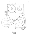
- FIG. 1 and 2 there are diagramatically illustrated the preferred embodiments of a longitudinal recording and/or reproducing apparatus according to the present invention.
- the shown embodiment of the longitudinal recording and/or reproducing apparatus is employed in a VTR.
- a VTR tape cassette 11 containing a VTR tape 10 is used for longitudinal recording.
- the VTR tape cassette 11 has a supply reel 12 and take-up reel 13.
- the VTR tape is wound around the supply reel 12 and the take-up reel 13 at each end.
- the VTR tape 10 is wrapped around the first and second head drums 15 and 16.
- tape guides 17, 18, 19, 20 and 21 are provided for loading the VTR tape 10 onto the first and second head drums 15 and 16, and for defining the tape path.
- tension levers 25 and 26 Adjacent to the tape path, tension levers 25 and 26 also are provided.
- the tension levers 25 and 26 are biased by means of coil springs 23 and 24 so as to provide tension for the VTR tape 10.
- the tension levers 25 and 26 are pivotable at one end and carry tape guides 27 and 28 at the other ends. Therefore, the tape guides 27 and 28 bias the tape for adjusting tension on the tape constant.
- capstans 29 and pinch roller 30 are provided for feeding the VTR tape.
- the second head drum 16 mates with the front surface of the VTR tape 10 for recording or reproducing the video signal on the peripheral surface.
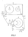
- the first head drum 15 mates the back side of the VTR tape 10 for performing recording and reproducing of the video signal on the back side. It should be appreciated that, when back side recording is unnecessary, single head drum can be used as shown in Fig. 2. In this case, the head drum 15 and the tape guide 17 can be omitted.
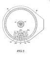
- Fig. 3 shows the detailed contruction of the rotary head drum 16 suitable to be employed in the preferred embodiments of the longitudinal recording and/or reproducing apparatus of Figs. 1 and 2, the construction of which is also suitable for the rotary head drum 15.
- the head drum 16 is sandwiched between flange guides 31 and 32.
- the flange guides 31 and 32 define the tape run path adjacent the rotary head drum 16.
- the rotary head drum 16 has an inner cylindrical section 16a fixedly mounted at the top of a hollow cylindrical rotary shaft 33.
- the rotary shaft 33 serves as an output shaft of a motor 34.
- the motor 34 has a motor housing 35.
- a boss 35a with a bearing 35b is formed at the bottom of the motor housing 35 in order to rotatably receive the rotary shaft 33.
- the motor housing 35 houses a stator coil 36 and a rotor magnet 37 in coaxial relationship to each other.
- the rotor magnet 37 is fixed to the rotary shaft 33 so as to rotate therewith. Therefore, the rotary shaft 33 is rotatingly driven by means of the motor 34 in order to rotate the rotary head drum 16.
- the rotary head drum 16 defines an annular groove 16b.
- a linear motor 38 is housed within the annular groove 16b.
- the linear motor 38 is fixedly mounted on the rotary head drum 16 by means of a mounting bracket 38a which is fixed to the bottom of the rotary head drum.
- the linear motor 38 comprises a a electromagnetic coil 39a and a stator core 39b.
- a movement 40 is also disposed within the annular groove 16b adjacent the linear motor 38.
- the movement 40 is coupled to the linear motor 38 so as to be driven by the latter to move with respect to the stator core.
- the movement 40 is mounted on a guide 40a which extends in parallel to the rotation axis of the rotary head drum 16. Therefore, the movement 40 is guided by the guide 40a to cause thrusting movement in the axial direction.
- a head support bracket 40b is fixedly mounted on the movement 40.
- the head support bracket 40b has a pair of radially extending legs 40c and 40d.
- a pair of magnetic heads 41 and 42 are mounted on the leg 40c and another pair of magnetic heads 43 and 44 are mounted on the leg 40d. Pairs of magnetic heads 41, 42 and 43 44 respectively forms azimuth-pair-heads. These two azimuth-pair-heads are axially aligned with each other.
- the magnetic heads 41 and 42 forming one azimuth-pair-head have azimuth gaps 41a and 42a of mutually different azimuth angles.
- the magnetic heads 43 and 44 form azimuth-pair-head of substantially identical construction as that of the azimuth-pair head formed by the magnetic heads 41 and 42.
- a pair of upper and lower circuit boards 45 and 46 are also disposed within the annular groove 16b.
- the upper circuit board 45 is connected to the magnetic heads 41, 42, 43 and 44 and contains serial-to-parallel converter circuit.
- the lower circuit board 46 contains a drive circuit for the aforementioned linear motor 38.
- the photo-coupling 47 opposes prisms 48 and 49 at both ends thereof.
- a light emitting element 50 and a light sensing element 51 are provided in the vicinity of the the prism 48.
- a light emitting element 52 and a light sensing element 53 are provided in the vicinity of the the prism 49.
- the light emitting element 52 and the light sensing element 53 are connected to amplifiers 54 and 55 respectively.
- Slip rings 56 are provided in the vicinity of the lower end of the rotary shaft 33.
- the slip rings 56 are connected to a power source to supply electric power to the circuit boards 45, 46, and the linear motor 38.
- Fig. 6 shows a diagram of the circuit associated with the rotary head drum 16.
- the light sensing element 51 is connected to a serial-to-parallel converter 60 via a light demodulator 59.
- the serial-to-parallel converter 60 is connected to the magnetic heads 41, 42, 43 and 44 via amplifiers 61 and recording terminals R of field switches 62.
- the light sensing element 51, the light demodulator 59, the serial-to-parallel converter 60, the amplifiers 61, and the field switches 62 constitute a recording circuit for recording data, such as a video signal, onto the magnetic tape.
- the field switches 62 have reproducing terminals P.
- the reproducing terminals P of the field switches 62 are connected to a parallel-to-serial converter 65 via amplifiers 63.
- the parallel-to-serial converter 64 is connected to a light emitting element 50 via a light modulator 65.
- the reproducing terminals P of the field switches 62, the amplifiers 63, the parallel-to-serial converter 64, the light modulator and the light emitting element 50 constitute a reproducing circuit for reproducing data stored on the magnetic tape.
- a controller 66 is provided for controlling the positions of the field switches 62, the serial-to-parallel converter 60, the parallel-to-serial converter 64 and the linear motor 38.
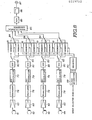
- Fig. 7 diagramatically and explanatorily illustrates a recording circuit in the preferred embodiment of the recording and/or reproducing apparatus.
- the serial-to-parallel converter 60 is connected to a data input terminal 67, such as a video input terminal, via a low-pass filter 68 and an analog-to-digital (A/D) converter 69.
- the outputs of the serial-to-parallel converter 60 are connected to error correction code (ECC) encoders 70.
- ECC encoders 70 is connected to a pair of field memories 71 and 72 via a switch 73.
- the field memories 71 and 72 are, in turn, connected to a modulator 75 via a switch 74.
- the modulator 75 is connected to its corresponding magnetic head 41, 2, 43 or 44 via an equalizer 76 and amplifier 61.
- Each of the field memories 71 and 72 is connected to a clock generator 89 via a selector 90.
- the clock generator 89 generates different frequencies of clock signals.
- the selector 90 selects one of the clock signals to supply the field memories 71 and 72. The data is written in and read from the field memories 71 an 72 based on the clock signal supplied from the selector 90.
- Fig. 8 explanatorily depicts a reproducing circuit in the preferred embodiment of the recording and/or reproducing circuit according to the invention.
- Each of the magnetic heads 41, 42, 43 and 44 are respectively connected to a pair of field memories 80 and 81 via associated amplifier 63, equalizer 78, demodulator 79, error correction code (ECC) demodulator 80 and switch 83.
- the switch 83 selectively connects the associated magnetic head 41, 45, 43 or 44 to one of the field memories 81 or 82 for writing data read from the associated magnetic head in selected one of the field memories 81 an 82.
- the outputs of the field memories 81 an 82 are connected to the parallel-to-serial converter 64.
- the parallel-to serial converter 64 is, in turn, connected to a data output terminal 87, such as a video output terminal, via a digital-to-analog converter 85 and, a low-pass filter 86.
- the field memories 81 and 82 are connected to the clock generator 89 via the selector 90 to be supplied therefrom the clock signal for time base correction in writing in and reading data.
- the magnetic tape 10 in the magnetic tape cassette 11 is extracted from the cassette and wrapped onto the periphery of the rotary head drums 15 and 16.
- the magnetic tape 10 is not wrapped on the periphery of the rotary head drums 15 and 16 in helical fashion to lie the tape axis oblique to the rotating direction of the drum, but in parallel fashion to lie the tape axis in parallel to the rotating direction of the drum.
- the rotary head drum 16 mates with the front surface of the magnetic tape 10.
- the rotary head drum 15 mates with the back side of the magnetic tape.
- both sides of the magnetic tape 10 are scanned by means of the rotary head drums 15 and 16.
- the magnetic heads 41, 42, 43 and 44 are arranged in alignment along the rotary axis of the rotary head drums 15 and 16.
- These magnetic heads 41, 42, 43 and 44 are fixedly mounted on the movement 40 which is associated with the linear motor 38 as set forth above and by which the magnetic heads 41, 42, 43 and 44 are shifted in the axial direction every scanning cycle.
- one scanning cycle is the period that the magnetic heads 41-44 are in contact with the tape 10 during one revolution of a rotary head drum 15 or 16.
- Operation of the linear motor 38 is synchronized with rotation of the rotary head drums 15 and 16. Namely, the linear motor 38 is driven to cause axial shift of the magnetic heads at the time when the magnetic heads 41, 42, 43 and 44 are not in contact with the magnetic tape 10. As will be seen from Fig. 1, the magnetic heads 41, 42, 43 and 44 are not in contact with the magnetic tape 10 in angular position range S (approximately 90°). Therefore, axial shift of the magnetic heads 41, 42, 43 and 44 takes place while the magnetic heads are in this angular range S. As is well known, the rotary head drums 15 and 16 rotate at a speed of 1/60 sec. (16.6 msec.) per cycle. Therefore, the period of time that the magnetic head is within the angular range S is about 4.15 msec. In the preferred embodiment, the linear motor 38 is designed to preform the axial shift of the magnetic heads 41, 42, 43 and 44 in 2 msec.
- the magnetic heads 43 and 44 forming the lower azimuth-pair-head form tracks No. 1, No. 2, No. 3 and No. 4 in sequence with an axial shift upwards occuring between every scanning cycle. Conversely while shifting downwards, the magnetic heads 43 and 44 form tracks No. 5, No. 6 and No. 7 with an axial shift downwards occuring between every scanning cycle.
- the magnetic heads 43 and 44 scan the No. 1 track first. After one scanning cycle, the magnetic heads 43 and 44 are shifted to mate with the No. 2 track to scan No. 2 track. Similarly, the magnetic heads 43 and 44 are shifted upwards once every scanning cycle to scan the No. 3 and No. 4 tracks. After reaching the No. 4 track and after one cycle of scanning on the No.
- the magnetic heads 43 and 44 are shifted downwards to mate with the No. 5 track which is formed between the No. 3 and No. 4 tracks. Similarly, between every scanning cycle, the magnetic heads 43 and 44 are shifted downward to scan the No. 6 and No. 7 tracks.
- the magnetic heads 41 and 42 forming the upper azimuth-pair-head are shifted upwardly and downwardly in synchronizm with axial shifting of the lower azimuth-pair-head to scan corresponding No. 1 to No. 7 tracks formed on the upper half of the magnetic tape 10.
- one field data i.e. one field of video data, is written in or read from the corresponding tracks.
- a high-density track pattern can be formed on the magnetic tape 10 with substantially no guard band between the adjacent tracks.
- the azimuth pattern of the upper half in each track becomes different from that in the lower half of the same track.
- the upper half of one track will have different azimuth pattern to that in the adjacent lower half of the upper adjacent track.
- the herring bone azimuth patterns created in the adjacent tracks successfully eliminate cross-talk between adjacent tracks. By providing differently oriented azimuth patterns in each track, high-density track formation with little or no guard band becomes possible.
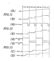
- Relationship between magnetic tape feed and the axial shift of the magnetic heads 41, 42, 43 and 44 are explanatorily illustrated in Fig. 11.
- the magnetic tape 10 is fed sequentially at a constant speed. Therefore, the magnetic heads 41, 42, 43 and 44 are released from the magnetic tape 10 at the angular range S of Fig. 1.
- the axial shift of the magnetic heads is executed to shift the magnetic heads to their corresponding tracks, as set forth above.
- the magnetic tape 10 is fed intermittently, the magnetic tape 10 is intermittently stopped while the magnetic heads 41, 42, 43 and 44 mate with the corresponding tracks. Shifting of the magnetic heads in the axial direction thus intermittently occurs while the magnetic heads are in the angular range S in Fig. 1.
- the magnetic heads are in the angular range S, the magnetic tape 10 is fed, as shown in Fig. 12. Furthermore, in the dual drum arrangement of Fig. 1, it would be possible to record and reproduce data on both sides of the magnetic tape alternately, as shown in Fig. 13. As will be seen from Fig. 13, in this both side recording or reproduction, the rotary head drums 15 and 16 are activated alternately during each scanning cycle. Axial shifting of the magnetic heads occurs in each rotary head drum 15 and 16 within the interval between the active cycles.
- Fig. 10 shows the track pattern formed in two directional recording, i.e. forward and revearse direction recording. It should be appreciated that two directional recording is possible in single sided recording or double sided recording.
- Single sided recording can be performed by the recording and/or reproducing apparatus of Fig. 2. As will be seen from Fig. 2, the single sided recording system will allow simple construction of the recording and/or reproducing apparatus. On the other hand, the double sided recording system will provide greater capacity of recording. For single sided recording, a single side coated magnetic tape can be used.
- the tracks No. 1, No. 2, No. 3 and No. 4 are formed in the same manner as that discussed with respect to Fig. 9.
- the tracks No. 1 through No. 7 and No. 8 in the upper half of the magnetic tape 10 are formed symmetrical opposite to the No. 1, No. 2, No. 3 and No. 4 tracks with respect to the longitudinal center axis of the magnetic tape.
- the starting points and end points of the No. 8, No. 7, No. 6 and No. 5 tracks are axially opposed to the corresponding positions to that of No. 1, No. 2, No. 3 and No. 4 tracks.
- This track pattern is essential for providing a high quality of video image without causing disturbance of the recorded or reproduced image.
- the No. 5 to No. 8 tracks are formed in the reverse direction recording or reproduction mode. Therefore, in the shown embodiment, the data is recorded in the No. 1, No. 2, No. 3 and No. 4 tracks and reproduced therefrom, while the magnetic tape 10 is fed in forward direction. On the other hand, while the magnetic tape is fed in reverse direction, recording and reproduction is performed with respect to the No. 5, No. 6, No. 7 and No. 8 tracks.
- the last track, i.e. No. 4 track in the forward recording is formed adjacent the first track, i.e. No. 5 track of the reverse direction recording.
- the rotary head drum rotates in the same direction as the tape feed direction in the forward feed. This means, that the tape feeding direction in the reverse feed becomes opposite to the rotating direction of the rotary head drum.
- the magnetic heads 41, 42, 43 and 44 (only head 41 is shown) on the rotary head drum 16 come into contact with the magnetic tape at the position shown in Fig. 14.
- the magnetic head 41 maintains contact with the magnetic tape in the angular range of about 270° as shown by the arrow in Fig. 14.
- the magnetic head 41 separates from the magnetic tape 10 at an angular position 270° shifted from the starting position in Fig. 14.
- the rotating direction of the rotary head drum 16 is same as the tape feeding direction in the forward feed mode, the relative rotation speed of the rotary head drum becomes lower to cause shortening of the track length to scan if scanning ends at 270° of the scanning start point. Therefore, the scanning end position may be angularly shifted at the angle ⁇ , therefore, the scanning remains to the position angularly advanced at the angle ⁇ as shown in Fig. 15. Therefore, the scanning end point has to be advance at the corresponding angle ⁇ . By advancing the scanning end points at the angle ⁇ , the track length can be maintained at about 3/4 of the peripheral length ( ⁇ D) of the rotary head drum.
- the magnetic tape is fed intermittently, as set forth with respect to Fig. 12. Therefore, the scanning start position of the magnetic head may not be shifted either in the advancing direction and retarding direction. Therefore, the scanning start position and the scanning end position are never shifted as shown in Figs. 18 and 19.
- the shifting angle can be N ⁇ in forward feed and -N ⁇ in reverse feed. Based on this shifting angle ⁇ or N ⁇ , wrapping angle ⁇ of the magnetic tape 10 with respect to the periphery of the rotary head drum is determined.
- the number of tracks to be formed by one magnetic head in one cycle is 7.
- step length s V/60
- the signal, e.g. video signal, to be recorded on the track is transmittead through the photo coupling 47 to the rotary head drum 16.
- the signal is received by the circuit on the circuit board 45 and is converted into parallel data therein. This parallel data is distributed to the magnetic heads 41, 42, 43 and 44.
- the photo coupling 47 also transmits a control signal for the linear motor 38.
- the linear motor control signal transmitted through the photo coupling is picked up by the circuit on the circuit board 46.
- the circuit board 46 controls operation of the linear motor 38.
- the magnetic heads 41, 42, 43 and 44 are axially shifted to scan the tracks.
- the outputs of the ECC encoders 70 are written in one of their respectively associated field memories 71 or 72.
- the stored data in the other field memory 72 or 71 is read out in a compressed form and applied to the associated magnetic heads 41, 42, 43 and 44 through the modulators 75, equalizers 76 and the amplifiers 61.
- a standard clock of the clock generator 89 is selected by the selector 90 and applied to the one of the field memories 71 or 72 into which the output data from the ECC encoder 70 is written through the switches 73.
- a clock having higher frequency than that of the standard clock is selected by the selector and applied.
- the frequency of the higher frequency clock is determined according to the relative speed between the magnetic tape and the magnetic heads. Adjustment of the clock frequency to be applied to the field memory from which data is read out, helps to maintain a constant track length irrespective of variation of the correction angle ⁇ .
- the magnetic heads 41, 42, 43 and 44 pick-up data on the magnetic tape 10 and feed the field memories 81 and 82 via respectively associated amplifiers 63, the equalizers 78, demodulators 79 and ECC recoders 80 and through the switches 83.
- the switch 83 selects one of the associated field memories 81 and 82 to write in the data transmitted from the ECC recoder 80.
- the write-timing for the selected one of the field memories 81 or 82 is determined by the clock applied by the selector 90. Therefore, the clock is selected by the selector so that the output data of the ECC recoder 80 can be written in the selected one of the field memory 81 or 82 within a predetermined period of time.
- the other field memory 82 or 81 is connected to the parallel-to-serial converter 64 via the switch 84 to read out the stored data. Reading of the stored data in the other field memory 82 or 81 is performed in real time. Therefore, the standard clock is selected by the selector 90 and applied thereto.
- the magnetic tape can be wrapped parallel to the rotating direction of the rotary head drum. This allows formation of the magnetic tape path in a single plane. Therefore, a simplified tape loading system and tape drive system can be employed for the recording and/or reproducing apparatus. Furthermore, since the tape guides for defining the tape path can be perpendicular to the tape run axis, rotary guides can be employed for smooth feeding of the tape. In addition, since the shown embodiment of the longitudinal recording and/or reproducing apparatus is designed for digital recording, influence in a reproduced video image of variation of bit-rate in recording and reproducing can be successfully avoided to allow high quality reproduced image in forward and reverse mode reproduction and in still mode reproduction. Furthermore, according to the shown embodiment, serial data transmission for the magnetic head can be employed. Additionally, in the serial data transmitted to the magnetic heads, the control signal for the head-shifting linear motor can be superimposed.
- the longitudinal recording and/or reproducing apparatus can be adapted not only for a single drum recording and/or reproducing system but also for a dual drum system.
- longitudinal recording system according to the invention When longitudinal recording system according to the invention is applied in a multi-drum system, both sided recording becomes possible significantly expanding recording capacity of the magnetic tape.
- the present invention allows dual direction recording and reproduction, trick-play becomes possible. Also, by allowing both direction recording and reproduction, access-time for the desired data can be drastically shortened.
- the track pattern to be formed on the magnetic tape in dual direction recording is set so that the scanning start positions and scanning end positions of the mutually corresponding tracks will have the same longitudinal position, disruption of the reproduced image upon reversing tape drive direction can be completely avoided.
- advantages can be achieved by forming tracks by means of azimuth-pair-head consisting of a pair of magnetic heads having different azimuth angles, in that cross-talk between adjacent tracks can be successfully prevented.
- the first group of tracks are formed during up-shifting of the azimuth-pair-head with track-to-track intervals, each of which corresponds to the width of a track.
- the second group of tracks are formed during down-shifting of the azimuth-pair-head in the track-to-track intervals left in the first group of tracks.
Priority Applications (1)
| Application Number | Priority Date | Filing Date | Title |
|---|---|---|---|
| AT87300378T ATE98036T1 (de) | 1986-01-16 | 1987-01-16 | Aufzeichnungs- oder wiedergabegeraet fuer longitudinale aufzeichnung. |
Applications Claiming Priority (2)
| Application Number | Priority Date | Filing Date | Title |
|---|---|---|---|
| JP6691/86 | 1986-01-16 | ||
| JP61006691A JP2633526B2 (ja) | 1986-01-16 | 1986-01-16 | 記録再生装置 |
Publications (3)
| Publication Number | Publication Date |
|---|---|
| EP0229732A2 true EP0229732A2 (de) | 1987-07-22 |
| EP0229732A3 EP0229732A3 (en) | 1988-12-07 |
| EP0229732B1 EP0229732B1 (de) | 1993-12-01 |
Family
ID=11645372
Family Applications (1)
| Application Number | Title | Priority Date | Filing Date |
|---|---|---|---|
| EP87300378A Expired - Lifetime EP0229732B1 (de) | 1986-01-16 | 1987-01-16 | Aufzeichnungs- oder Wiedergabegerät für longitudinale Aufzeichnung |
Country Status (9)
| Country | Link |
|---|---|
| US (1) | US4819099A (de) |
| EP (1) | EP0229732B1 (de) |
| JP (1) | JP2633526B2 (de) |
| KR (1) | KR960016493B1 (de) |
| CN (1) | CN1009595B (de) |
| AT (1) | ATE98036T1 (de) |
| AU (1) | AU598506B2 (de) |
| CA (1) | CA1303730C (de) |
| DE (1) | DE3788288T2 (de) |
Cited By (7)
| Publication number | Priority date | Publication date | Assignee | Title |
|---|---|---|---|---|
| FR2623041A1 (fr) * | 1987-10-16 | 1989-05-12 | Sony Corp | Systeme d'analyse longitudinale pour un appareil d'enregistrement/lecture a bande et tambour,notamment pour un magnetoscope |
| GB2244170A (en) * | 1987-07-01 | 1991-11-20 | Sony Corp | Magnetic disc recording/reproducing apparatus |
| EP0563780A1 (de) * | 1992-03-31 | 1993-10-06 | Sony Corporation | Methode zur magnetischen Aufzeichnung und Wiedergabe |
| WO1994000839A1 (en) * | 1992-06-24 | 1994-01-06 | Digital Equipment Corporation | Method for very high track density magnetic recording |
| FR2699723A1 (fr) * | 1992-12-22 | 1994-06-24 | Thomson Csf | Support d'enregistrement d'informations, enregistreur, lecteur et procédé d'enregistrement. |
| EP0678854A2 (de) * | 1994-04-22 | 1995-10-25 | Deutsche Thomson-Brandt Gmbh | Verfahren zur Aufzeichnung eines digitalen Signals |
| US5949604A (en) * | 1992-06-24 | 1999-09-07 | Quantum Corporation | Method of writing and reading servo on tracks having a longitudinal gap |
Families Citing this family (6)
| Publication number | Priority date | Publication date | Assignee | Title |
|---|---|---|---|---|
| US4905093A (en) * | 1987-06-23 | 1990-02-27 | Canon Kabushiki Kaisha | Video reproduction apparatus with plural heads and field memory |
| JP2695186B2 (ja) * | 1988-05-09 | 1997-12-24 | シャープ株式会社 | 回転ドラムヘッド磁気テープ再生装置 |
| JPH0719337B2 (ja) * | 1988-05-10 | 1995-03-06 | シャープ株式会社 | 回転ドラムヘッド磁気テープ再生方式 |
| KR940001564B1 (ko) * | 1991-08-31 | 1994-02-24 | 삼성전자 주식회사 | 자기기록 재생장치 |
| JPH06131618A (ja) * | 1991-12-27 | 1994-05-13 | Teac Corp | 磁気テ−プにおける基準信号の記録再生方法 |
| JP3900494B2 (ja) * | 2003-05-16 | 2007-04-04 | インターナショナル・ビジネス・マシーンズ・コーポレーション | 記憶装置、制御方法、プログラム、及び記録媒体 |
Citations (8)
| Publication number | Priority date | Publication date | Assignee | Title |
|---|---|---|---|---|
| US4040109A (en) * | 1975-08-11 | 1977-08-02 | Igor Alexeevich Kryltsov | Tape transport system of video tape recorder with longitudinal recording |
| JPS5390718A (en) * | 1977-01-20 | 1978-08-09 | Sony Corp | Nagnetic picture recorder/reproducer |
| JPS5740706A (en) * | 1980-08-22 | 1982-03-06 | Toshiba Corp | Tape recording and reproducing device |
| JPS58220202A (ja) * | 1982-06-15 | 1983-12-21 | Sony Corp | 磁気記録再生装置 |
| JPS59104703A (ja) * | 1982-12-03 | 1984-06-16 | Sharp Corp | ビデオテ−プへの信号記録方式 |
| JPS60106014A (ja) * | 1983-11-14 | 1985-06-11 | Matsushita Electric Ind Co Ltd | 磁気記録再生装置 |
| JPS60212801A (ja) * | 1984-04-09 | 1985-10-25 | Matsushita Electric Ind Co Ltd | 往復記録再生方式 |
| EP0197333A2 (de) * | 1985-03-16 | 1986-10-15 | Deutsche Thomson-Brandt GmbH | Verfahren zur Aufzeichnung eines Signals auf einen bandförmigen Aufzeichnungsträger |
Family Cites Families (10)
| Publication number | Priority date | Publication date | Assignee | Title |
|---|---|---|---|---|
| US3294902A (en) * | 1963-12-30 | 1966-12-27 | Ampex | Fast, slow and stop motion reproduction using longitudinal recording and rotating heads |
| FR2405536A1 (fr) * | 1977-10-07 | 1979-05-04 | Thomson Csf | Dispositif d'enregistrement-lecture d'une information sur une boucle de ruban magnetique enroule dans une cassette sans fin |
| JPS5593530A (en) * | 1978-12-29 | 1980-07-16 | Sony Corp | Magnetic head unit |
| US4285016A (en) * | 1979-06-04 | 1981-08-18 | Microcomputer Systems Corp. | Disc, tape and hybrid disc-tape memory apparatus and drive assembly |
| IT1121850B (it) * | 1979-06-20 | 1986-04-23 | Montedison Spa | Pol-carbossi-alchil-cellulose ad ritezione dei fluidi e processo per la loro preparazione |
| AT365353B (de) * | 1979-07-20 | 1982-01-11 | Philips Nv | Aufzeichnungs- und/oder wiedergabegeraet |
| JPS56159858A (en) * | 1980-05-10 | 1981-12-09 | Sony Corp | Tracking control unit in magnetic recording and reproducing device |
| JPS58161108A (ja) * | 1982-03-19 | 1983-09-24 | Sony Corp | 磁気記録再生装置 |
| JPS5937783A (ja) * | 1982-08-25 | 1984-03-01 | Sony Corp | 映像信号の記録装置 |
| JPS6050603A (ja) * | 1983-08-29 | 1985-03-20 | Toshiba Corp | 磁気記録再生装置 |
-
1986
- 1986-01-16 JP JP61006691A patent/JP2633526B2/ja not_active Expired - Lifetime
- 1986-12-16 US US06/942,413 patent/US4819099A/en not_active Expired - Lifetime
- 1986-12-17 CA CA000525553A patent/CA1303730C/en not_active Expired - Lifetime
-
1987
- 1987-01-14 AU AU67549/87A patent/AU598506B2/en not_active Ceased
- 1987-01-15 CN CN87100326A patent/CN1009595B/zh not_active Expired
- 1987-01-16 KR KR1019870000291A patent/KR960016493B1/ko not_active IP Right Cessation
- 1987-01-16 EP EP87300378A patent/EP0229732B1/de not_active Expired - Lifetime
- 1987-01-16 AT AT87300378T patent/ATE98036T1/de not_active IP Right Cessation
- 1987-01-16 DE DE87300378T patent/DE3788288T2/de not_active Expired - Fee Related
Patent Citations (8)
| Publication number | Priority date | Publication date | Assignee | Title |
|---|---|---|---|---|
| US4040109A (en) * | 1975-08-11 | 1977-08-02 | Igor Alexeevich Kryltsov | Tape transport system of video tape recorder with longitudinal recording |
| JPS5390718A (en) * | 1977-01-20 | 1978-08-09 | Sony Corp | Nagnetic picture recorder/reproducer |
| JPS5740706A (en) * | 1980-08-22 | 1982-03-06 | Toshiba Corp | Tape recording and reproducing device |
| JPS58220202A (ja) * | 1982-06-15 | 1983-12-21 | Sony Corp | 磁気記録再生装置 |
| JPS59104703A (ja) * | 1982-12-03 | 1984-06-16 | Sharp Corp | ビデオテ−プへの信号記録方式 |
| JPS60106014A (ja) * | 1983-11-14 | 1985-06-11 | Matsushita Electric Ind Co Ltd | 磁気記録再生装置 |
| JPS60212801A (ja) * | 1984-04-09 | 1985-10-25 | Matsushita Electric Ind Co Ltd | 往復記録再生方式 |
| EP0197333A2 (de) * | 1985-03-16 | 1986-10-15 | Deutsche Thomson-Brandt GmbH | Verfahren zur Aufzeichnung eines Signals auf einen bandförmigen Aufzeichnungsträger |
Non-Patent Citations (8)
| Title |
|---|
| IBM TECHNICAL DISCLOSURE BULLETIN, vol. 15, no. 11, April 1973, page 3468, New York, US; H.J. ZENTGRAF: "Dual-sided magnetic recording" * |
| IBM TECHNICAL DISCLOSURE BULLETIN, vol. 22, no. 4, September 1979, pages 1714-1716, New York, US; E.W. PUGH: "New format video recorder", * |
| IBM TECHNICAL DISCLOSURE BULLETIN, vol. 8, no. 7, December 1965, pages 943-944, New York, US; J.J. HAGOPIAN: "SPROCKETED-TAPE MAGNETIC VIDEO RECORDER" * |
| PATENT ABSTRACTS OF JAPAN, vol. 2, no. 124, 18th October 1978, page 7325 E 78; & JP-A-53 90 718 (SONY K.K.) 09-08-1978 * |
| PATENT ABSTRACTS OF JAPAN, vol. 6, no. 112 (P-124)[990], 23rd June 1982; & JP-A-57 40 706 (TOKYO SHIBAURA DENKI K.K.) 06-03-1982 * |
| PATENT ABSTRACTS OF JAPAN, vol. 8, no. 223 (P-307)[1660], 12th October 1984; & JP-A-59 104 703 (SHARP K.K.) 16-06-1984 * |
| PATENT ABSTRACTS OF JAPAN, vol. 8, no. 75 (P-266)[1512], 7th April 1984; & JP-A-58 220 202 (SONY K.K.) 21-12-1983 * |
| PATENT ABSTRACTS OF JAPAN, vol. 9, no. 257 (P-396)[1980], 15th October 1985; & JP-A-60 106 014 (MATSUSHITA DENKI SANGYO K.K.) 11-06-1985 * |
Cited By (12)
| Publication number | Priority date | Publication date | Assignee | Title |
|---|---|---|---|---|
| GB2244170A (en) * | 1987-07-01 | 1991-11-20 | Sony Corp | Magnetic disc recording/reproducing apparatus |
| FR2623041A1 (fr) * | 1987-10-16 | 1989-05-12 | Sony Corp | Systeme d'analyse longitudinale pour un appareil d'enregistrement/lecture a bande et tambour,notamment pour un magnetoscope |
| EP0563780A1 (de) * | 1992-03-31 | 1993-10-06 | Sony Corporation | Methode zur magnetischen Aufzeichnung und Wiedergabe |
| US5349478A (en) * | 1992-03-31 | 1994-09-20 | Sony Corporation | Magnetic recording and/or reproducing method having a double azimuth head arrangement |
| WO1994000839A1 (en) * | 1992-06-24 | 1994-01-06 | Digital Equipment Corporation | Method for very high track density magnetic recording |
| US5949604A (en) * | 1992-06-24 | 1999-09-07 | Quantum Corporation | Method of writing and reading servo on tracks having a longitudinal gap |
| FR2699723A1 (fr) * | 1992-12-22 | 1994-06-24 | Thomson Csf | Support d'enregistrement d'informations, enregistreur, lecteur et procédé d'enregistrement. |
| WO1994015334A1 (fr) * | 1992-12-22 | 1994-07-07 | Thomson-Csf | Support d'enregistrement d'informations, enregistreur, lecteur et procede d'enregistrement |
| US5640285A (en) * | 1992-12-22 | 1997-06-17 | Thomson-Csf | Information recording medium encoded to enable track following |
| US5796710A (en) * | 1992-12-22 | 1998-08-18 | Thomson-Csf | Information recording medium encoded to enable track following and method of recording |
| EP0678854A2 (de) * | 1994-04-22 | 1995-10-25 | Deutsche Thomson-Brandt Gmbh | Verfahren zur Aufzeichnung eines digitalen Signals |
| EP0678854A3 (de) * | 1994-04-22 | 1996-08-28 | Thomson Brandt Gmbh | Verfahren zur Aufzeichnung eines digitalen Signals. |
Also Published As
| Publication number | Publication date |
|---|---|
| ATE98036T1 (de) | 1993-12-15 |
| AU6754987A (en) | 1987-07-23 |
| JPS62165705A (ja) | 1987-07-22 |
| EP0229732B1 (de) | 1993-12-01 |
| JP2633526B2 (ja) | 1997-07-23 |
| CN1009595B (zh) | 1990-09-12 |
| US4819099A (en) | 1989-04-04 |
| AU598506B2 (en) | 1990-06-28 |
| DE3788288D1 (de) | 1994-01-13 |
| EP0229732A3 (en) | 1988-12-07 |
| KR960016493B1 (ko) | 1996-12-12 |
| CA1303730C (en) | 1992-06-16 |
| DE3788288T2 (de) | 1994-03-31 |
| CN87100326A (zh) | 1987-09-09 |
| KR870007482A (ko) | 1987-08-19 |
Similar Documents
| Publication | Publication Date | Title |
|---|---|---|
| US4819099A (en) | Apparatus for longitudinal bidirectional recording with equal length tracks | |
| US4358799A (en) | Apparatus for recording and/or reproducing signals | |
| EP0197782B1 (de) | Gerät für die Wiedergabe digitaler Signale | |
| EP0177231B1 (de) | Digitale Video-Aufzeichnung | |
| US4851940A (en) | Longitudinal recording and/or reproducing apparatus | |
| US4314284A (en) | Video head deflection apparatus for special motion reproduction by helical scan VTR | |
| JPS62184652A (ja) | 記録再生装置 | |
| US5481413A (en) | Magnetic recording and reproducing apparatus for a helical-scan system adapted for reproduction of data in a reverse sequential order from recording of data | |
| EP0265987B1 (de) | Bandtransportvorrichtung und Bandverarbeitungsgerät mit einer solchen Bandtransportvorrichtung | |
| JPS62184601A (ja) | 記録再生装置 | |
| JPS62165704A (ja) | 記録再生装置 | |
| US5270891A (en) | Vertically distant magnetic head units with piezoelectric error tracking | |
| JPH0715721B2 (ja) | 記録再生装置 | |
| JPH0722749Y2 (ja) | 磁気記録再生装置 | |
| JPS62184648A (ja) | 記録再生装置 | |
| JPS62184654A (ja) | 記録再生装置 | |
| JPS62165703A (ja) | 記録再生装置 | |
| JPH04184747A (ja) | 記録または再生装置 | |
| JP3096912B2 (ja) | 記録再生装置 | |
| JPS6340485A (ja) | 記録再生装置 | |
| JP2003196898A (ja) | 磁気記録再生装置 | |
| JP2003036501A (ja) | 磁気記録再生装置 | |
| JP2002304714A (ja) | 磁気記録再生装置 | |
| JPS63168804A (ja) | 記録再生装置 | |
| JPS62252511A (ja) | 磁気記録再生装置 |
Legal Events
| Date | Code | Title | Description |
|---|---|---|---|
| PUAI | Public reference made under article 153(3) epc to a published international application that has entered the european phase |
Free format text: ORIGINAL CODE: 0009012 |
|
| 17P | Request for examination filed |
Effective date: 19870122 |
|
| AK | Designated contracting states |
Kind code of ref document: A2 Designated state(s): AT DE FR GB NL |
|
| PUAL | Search report despatched |
Free format text: ORIGINAL CODE: 0009013 |
|
| AK | Designated contracting states |
Kind code of ref document: A3 Designated state(s): AT DE FR GB NL |
|
| 17Q | First examination report despatched |
Effective date: 19901016 |
|
| GRAA | (expected) grant |
Free format text: ORIGINAL CODE: 0009210 |
|
| AK | Designated contracting states |
Kind code of ref document: B1 Designated state(s): AT DE FR GB NL |
|
| REF | Corresponds to: |
Ref document number: 98036 Country of ref document: AT Date of ref document: 19931215 Kind code of ref document: T |
|
| REF | Corresponds to: |
Ref document number: 3788288 Country of ref document: DE Date of ref document: 19940113 |
|
| ET | Fr: translation filed | ||
| PLBE | No opposition filed within time limit |
Free format text: ORIGINAL CODE: 0009261 |
|
| STAA | Information on the status of an ep patent application or granted ep patent |
Free format text: STATUS: NO OPPOSITION FILED WITHIN TIME LIMIT |
|
| 26N | No opposition filed | ||
| REG | Reference to a national code |
Ref country code: GB Ref legal event code: IF02 |
|
| PGFP | Annual fee paid to national office [announced via postgrant information from national office to epo] |
Ref country code: FR Payment date: 20020110 Year of fee payment: 16 |
|
| PGFP | Annual fee paid to national office [announced via postgrant information from national office to epo] |
Ref country code: AT Payment date: 20020111 Year of fee payment: 16 |
|
| PGFP | Annual fee paid to national office [announced via postgrant information from national office to epo] |
Ref country code: GB Payment date: 20020116 Year of fee payment: 16 |
|
| PGFP | Annual fee paid to national office [announced via postgrant information from national office to epo] |
Ref country code: NL Payment date: 20020131 Year of fee payment: 16 |
|
| PGFP | Annual fee paid to national office [announced via postgrant information from national office to epo] |
Ref country code: DE Payment date: 20020212 Year of fee payment: 16 |
|
| PG25 | Lapsed in a contracting state [announced via postgrant information from national office to epo] |
Ref country code: GB Free format text: LAPSE BECAUSE OF NON-PAYMENT OF DUE FEES Effective date: 20030116 Ref country code: AT Free format text: LAPSE BECAUSE OF NON-PAYMENT OF DUE FEES Effective date: 20030116 |
|
| PG25 | Lapsed in a contracting state [announced via postgrant information from national office to epo] |
Ref country code: NL Free format text: LAPSE BECAUSE OF NON-PAYMENT OF DUE FEES Effective date: 20030801 Ref country code: DE Free format text: LAPSE BECAUSE OF NON-PAYMENT OF DUE FEES Effective date: 20030801 |
|
| GBPC | Gb: european patent ceased through non-payment of renewal fee | ||
| PG25 | Lapsed in a contracting state [announced via postgrant information from national office to epo] |
Ref country code: FR Free format text: LAPSE BECAUSE OF NON-PAYMENT OF DUE FEES Effective date: 20030930 |
|
| NLV4 | Nl: lapsed or anulled due to non-payment of the annual fee |
Effective date: 20030801 |
|
| REG | Reference to a national code |
Ref country code: FR Ref legal event code: ST |