EP0229399A2 - Dispositif pour la transmission de signaux sans fil à partir d'un corps en rotation - Google Patents
Dispositif pour la transmission de signaux sans fil à partir d'un corps en rotation Download PDFInfo
- Publication number
- EP0229399A2 EP0229399A2 EP86118165A EP86118165A EP0229399A2 EP 0229399 A2 EP0229399 A2 EP 0229399A2 EP 86118165 A EP86118165 A EP 86118165A EP 86118165 A EP86118165 A EP 86118165A EP 0229399 A2 EP0229399 A2 EP 0229399A2
- Authority
- EP
- European Patent Office
- Prior art keywords
- transmitter
- rotating body
- receiver
- housing
- unit
- Prior art date
- Legal status (The legal status is an assumption and is not a legal conclusion. Google has not performed a legal analysis and makes no representation as to the accuracy of the status listed.)
- Granted
Links
- 230000008054 signal transmission Effects 0.000 title claims description 3
- 238000012545 processing Methods 0.000 claims abstract description 16
- 238000006243 chemical reaction Methods 0.000 claims description 4
- 230000002093 peripheral effect Effects 0.000 claims 1
- 238000002485 combustion reaction Methods 0.000 description 4
- 238000013461 design Methods 0.000 description 2
- 238000005553 drilling Methods 0.000 description 2
- 230000005540 biological transmission Effects 0.000 description 1
- 238000004891 communication Methods 0.000 description 1
- 238000005520 cutting process Methods 0.000 description 1
- 238000011161 development Methods 0.000 description 1
- 238000011156 evaluation Methods 0.000 description 1
- 230000007717 exclusion Effects 0.000 description 1
- 230000001939 inductive effect Effects 0.000 description 1
- 238000005461 lubrication Methods 0.000 description 1
- 238000003754 machining Methods 0.000 description 1
- 238000005259 measurement Methods 0.000 description 1
- 238000003801 milling Methods 0.000 description 1
- 238000012806 monitoring device Methods 0.000 description 1
- 238000012544 monitoring process Methods 0.000 description 1
- 230000010355 oscillation Effects 0.000 description 1
- 230000002028 premature Effects 0.000 description 1
- 238000003860 storage Methods 0.000 description 1
Images


Classifications
-
- B—PERFORMING OPERATIONS; TRANSPORTING
- B23—MACHINE TOOLS; METAL-WORKING NOT OTHERWISE PROVIDED FOR
- B23Q—DETAILS, COMPONENTS, OR ACCESSORIES FOR MACHINE TOOLS, e.g. ARRANGEMENTS FOR COPYING OR CONTROLLING; MACHINE TOOLS IN GENERAL CHARACTERISED BY THE CONSTRUCTION OF PARTICULAR DETAILS OR COMPONENTS; COMBINATIONS OR ASSOCIATIONS OF METAL-WORKING MACHINES, NOT DIRECTED TO A PARTICULAR RESULT
- B23Q1/00—Members which are comprised in the general build-up of a form of machine, particularly relatively large fixed members
- B23Q1/0009—Energy-transferring means or control lines for movable machine parts; Control panels or boxes; Control parts
-
- B—PERFORMING OPERATIONS; TRANSPORTING
- B23—MACHINE TOOLS; METAL-WORKING NOT OTHERWISE PROVIDED FOR
- B23B—TURNING; BORING
- B23B31/00—Chucks; Expansion mandrels; Adaptations thereof for remote control
- B23B31/02—Chucks
- B23B31/10—Chucks characterised by the retaining or gripping devices or their immediate operating means
- B23B31/12—Chucks with simultaneously-acting jaws, whether or not also individually adjustable
- B23B31/1207—Chucks with simultaneously-acting jaws, whether or not also individually adjustable moving obliquely to the axis of the chuck in a plane containing this axis
- B23B31/1253—Jaws movement actuated by an axially movable member
-
- B—PERFORMING OPERATIONS; TRANSPORTING
- B23—MACHINE TOOLS; METAL-WORKING NOT OTHERWISE PROVIDED FOR
- B23Q—DETAILS, COMPONENTS, OR ACCESSORIES FOR MACHINE TOOLS, e.g. ARRANGEMENTS FOR COPYING OR CONTROLLING; MACHINE TOOLS IN GENERAL CHARACTERISED BY THE CONSTRUCTION OF PARTICULAR DETAILS OR COMPONENTS; COMBINATIONS OR ASSOCIATIONS OF METAL-WORKING MACHINES, NOT DIRECTED TO A PARTICULAR RESULT
- B23Q1/00—Members which are comprised in the general build-up of a form of machine, particularly relatively large fixed members
- B23Q1/0009—Energy-transferring means or control lines for movable machine parts; Control panels or boxes; Control parts
- B23Q1/0045—Control panels or boxes
-
- B—PERFORMING OPERATIONS; TRANSPORTING
- B23—MACHINE TOOLS; METAL-WORKING NOT OTHERWISE PROVIDED FOR
- B23Q—DETAILS, COMPONENTS, OR ACCESSORIES FOR MACHINE TOOLS, e.g. ARRANGEMENTS FOR COPYING OR CONTROLLING; MACHINE TOOLS IN GENERAL CHARACTERISED BY THE CONSTRUCTION OF PARTICULAR DETAILS OR COMPONENTS; COMBINATIONS OR ASSOCIATIONS OF METAL-WORKING MACHINES, NOT DIRECTED TO A PARTICULAR RESULT
- B23Q15/00—Automatic control or regulation of feed movement, cutting velocity or position of tool or work
-
- B—PERFORMING OPERATIONS; TRANSPORTING
- B23—MACHINE TOOLS; METAL-WORKING NOT OTHERWISE PROVIDED FOR
- B23Q—DETAILS, COMPONENTS, OR ACCESSORIES FOR MACHINE TOOLS, e.g. ARRANGEMENTS FOR COPYING OR CONTROLLING; MACHINE TOOLS IN GENERAL CHARACTERISED BY THE CONSTRUCTION OF PARTICULAR DETAILS OR COMPONENTS; COMBINATIONS OR ASSOCIATIONS OF METAL-WORKING MACHINES, NOT DIRECTED TO A PARTICULAR RESULT
- B23Q3/00—Devices holding, supporting, or positioning work or tools, of a kind normally removable from the machine
- B23Q3/155—Arrangements for automatic insertion or removal of tools, e.g. combined with manual handling
- B23Q3/157—Arrangements for automatic insertion or removal of tools, e.g. combined with manual handling of rotary tools
-
- G—PHYSICS
- G08—SIGNALLING
- G08C—TRANSMISSION SYSTEMS FOR MEASURED VALUES, CONTROL OR SIMILAR SIGNALS
- G08C23/00—Non-electrical signal transmission systems, e.g. optical systems
- G08C23/04—Non-electrical signal transmission systems, e.g. optical systems using light waves, e.g. infrared
-
- Y—GENERAL TAGGING OF NEW TECHNOLOGICAL DEVELOPMENTS; GENERAL TAGGING OF CROSS-SECTIONAL TECHNOLOGIES SPANNING OVER SEVERAL SECTIONS OF THE IPC; TECHNICAL SUBJECTS COVERED BY FORMER USPC CROSS-REFERENCE ART COLLECTIONS [XRACs] AND DIGESTS
- Y10—TECHNICAL SUBJECTS COVERED BY FORMER USPC
- Y10T—TECHNICAL SUBJECTS COVERED BY FORMER US CLASSIFICATION
- Y10T408/00—Cutting by use of rotating axially moving tool
- Y10T408/13—Cutting by use of rotating axially moving tool with randomly-actuated stopping means
- Y10T408/14—Responsive to condition of Tool or tool-drive
-
- Y—GENERAL TAGGING OF NEW TECHNOLOGICAL DEVELOPMENTS; GENERAL TAGGING OF CROSS-SECTIONAL TECHNOLOGIES SPANNING OVER SEVERAL SECTIONS OF THE IPC; TECHNICAL SUBJECTS COVERED BY FORMER USPC CROSS-REFERENCE ART COLLECTIONS [XRACs] AND DIGESTS
- Y10—TECHNICAL SUBJECTS COVERED BY FORMER USPC
- Y10T—TECHNICAL SUBJECTS COVERED BY FORMER US CLASSIFICATION
- Y10T408/00—Cutting by use of rotating axially moving tool
- Y10T408/16—Cutting by use of rotating axially moving tool with control means energized in response to activator stimulated by condition sensor
- Y10T408/17—Cutting by use of rotating axially moving tool with control means energized in response to activator stimulated by condition sensor to control infeed
- Y10T408/172—Responsive to Tool
-
- Y—GENERAL TAGGING OF NEW TECHNOLOGICAL DEVELOPMENTS; GENERAL TAGGING OF CROSS-SECTIONAL TECHNOLOGIES SPANNING OVER SEVERAL SECTIONS OF THE IPC; TECHNICAL SUBJECTS COVERED BY FORMER USPC CROSS-REFERENCE ART COLLECTIONS [XRACs] AND DIGESTS
- Y10—TECHNICAL SUBJECTS COVERED BY FORMER USPC
- Y10T—TECHNICAL SUBJECTS COVERED BY FORMER US CLASSIFICATION
- Y10T408/00—Cutting by use of rotating axially moving tool
- Y10T408/21—Cutting by use of rotating axially moving tool with signal, indicator, illuminator or optical means
Definitions
- the invention relates to a device for the wireless transmission of signals from a rotating body to a stationary receiving station, with a power supply device at least partially accommodated in the rotating body, wherein in the rotating body a detector that detects an operating state change, a transmitting unit that sends signals to the receiving station, and an electrical circuit are installed.
- Such a device is known from US-A-4,090,802.
- the detector consists of a mechanical torque clutch that responds when overloaded and closes a switch that activates a high-frequency transmitter.
- the signal is received by the fixed receiving station and e.g. displayed akküstisch.
- the device only speaks to a very specific change in the operating state, e.g. a broken tool.
- DE-B-1,402,917 describes a device for monitoring tool wear on a rotating tool spindle, with a pressure transducer installed in the spindle head, i.e. stationary, which is electrically connected to a fixed amplifier and a display device.
- the axial reaction forces transmitted from the tool to the spindle head are a measure of the wear of the tool, so that the operating states of the tool can be continuously monitored.
- this system is subject to interference, e.g. due to vibrations of the machine frame, the properties of the thrust bearing and other external influences.
- the object of the invention is to provide a device of the type mentioned at the outset, with which it is possible to detect any changes in the operating state of the rotating body or of an object carried by it, with the exclusion of any external influences, the possibility also being given that To be able to influence signal output from the outside.
- the rotating body has a receiver unit for signal reception from a fixed transmitter station and an electronic signal processing device with amplifier part which is electrically connected to the transmitter and receiver units and by means of which the signal output of the transmitter unit can be influenced by the signal reception of the receiver unit, and that the detector is designed as a highly sensitive sensor which detects infinitesimal operating state changes.
- the new device allows ongoing or intermittent communication between the fixed transmitting and receiving station and the rotating body, so that any operating conditions, such as clamping force, condition of the cutting edge of a tool, start, course and end of machining, condition of the workpiece, etc. can be queried can be.
- the signal processing device can automatically activate the amplifier part and the transmission unit when detecting certain operating states, for example a certain oscillation pattern, in order to warn, for example, of an imminent breakage of a tool or of the workpiece and / or to stop the machine.
- turbines for example, can be stopped automatically if a detected imbalance or vibration indicates the presence of foreign bodies in the area of the turbine blades.
- a further development of the invention consists in that at least the amplifier part of the signal processing device can be activated by signal reception of the receiver unit. This enables a power supply through built-in button cells, since the power consumption of the electronic signal processing device is low and the amplifier part with the transmitter unit is only activated upon a corresponding signal from the stationary transmitter station
- the transmitter unit comprises a plurality of circumferentially offset transmitter elements, which lie approximately in the same radial plane
- the receiver unit comprises at least one receiver element arranged in the same radial plane
- the transmitter unit preferably has infrared light-emitting diodes and the receiver unit preferably has infrared photodiodes or transistors.
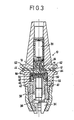
- the rotating body is designed as a chuck for tools or workpieces, with a multi-part screwed housing with a sliding member for clamping jaws and a rotary member which can be screwed to it and can be actuated from the outside by means of a key and has an outer flange between the and one Ring shoulder of the housing, a ball bearing ring, a non-rotatable support ring and an annular body are used, the latter having a plurality of pressure sensors arranged at circumferential intervals, which are pretensioned by the axial component of the reaction clamping force of the clamped tool.
- Radial bores are preferably provided in circumferential spacings in an outer gripper groove of the housing of the chuck, which penetrate the circumferential wall of the housing and to which each of the transmitter and receiver diodes are assigned in radial alignment in the interior of the housing, the radial bores being closed to the outside by a translucent material. Thanks to this design, the transmitter and receiver diodes do not have to be separately attached to the housing and wired to the signal processing device, but form a structural unit with it which can be replaced as a whole.
- the electronic signal processing device preferably has a plurality of printed circuit boards arranged in parallel to one another and equipped with electrical and electronic elements, which are cast in a circular-cylindrical block, which is connected to the larger-diameter ring body to form an axially insertable structural unit which is rotatably mounted in the housing.
- the transmitter and receiver diodes are preferably arranged on the outer circumference of the block. According to an important feature, the boards are arranged in the block in radial planes or axially parallel planes.
- the rotating body can also, according to further embodiments of the invention, be fastened to or integrated in a shaft which belongs to a group which includes drive shafts of machines, pumps, turbines and rotors, and crankshafts.
- a shaft which belongs to a group which includes drive shafts of machines, pumps, turbines and rotors, and crankshafts.
- a chuck 10 of a drilling or milling machine shows B ine number in the bottom of the gripper groove 12 arranged at circumferential radial bores 62, with which radially aligned inside the chuck arranged transmitter diodes 14 and receiver diodes 16 are provided.
- transmitter diodes 14 and receiver diodes 16 are provided in the rotational plane of these transmitter and receiver diodes 14, 16 there is a fixed transmitter and receiver station 18 at a distance next to the chuck 10, which station is attached to the machine frame and is electrically connected to a control, control and display unit 22 via the line 20.
- a primary coil 26 is inserted into the spindle head 24, which is opposite a secondary coil 28 in the chuck 10 for an inductive power supply.
- the power supply is alternatively provided by a built-in battery 30.
- the chuck 10 consists of a two-part housing 32, clamping jaws 34, which are guided in a sliding member 36, which can be screwed into a rotary member 38, which in turn is in a known manner via a worm shaft 40 from is rotatable outside by means of a key.
- a ball bearing ring 46, a support ring 48 and a ring body 50 are arranged between a flange 42 of the rotary member 38 and an annular shoulder 44 of the housing 32.
- the support ring 48 carries an axially projecting pin 52 which passes through the ring body 50 and into a blind hole in the ring shoulder 44 of the housing 32 to prevent rotation takes hold.
- the ring body 50 and a circular cylindrical block 54 adjoining it on the rear form a structural unit which contains the entire electronics.
- three pairs of pressure sensors 56 are arranged at the same circumferential intervals.
- block 54 there are four parallel boards 60 equipped with electronic components 58, which in the embodiment according to FIG. 4 in radial planes and in the embodiment according to FIG. 6 are arranged in axially parallel planes.
- the electrical or electronic components 58 are internally wired and form a signal processing device which is electrically connected to the sensors 56.
- the transmitter diodes 14 and the receiver diodes 16 are arranged alternately at circumferential intervals in a radial plane and are electrically connected to an amplifier part of the signal processing device.
- Each of these diodes 14, 16 is assigned a radial bore 62 in the shaft of the housing 32, through which the infrared signals of the diodes 14, 16 can enter or exit.
- the bores 62 are poured out with a translucent material 64.
- annular molded block 154 is fastened on a shaft 100 of a turbine 102 and contains the signal processing device, which is connected via a cable to a sensor 156, which is inserted in a radial bore of the shaft 100 and is pretensioned by means of a screw sleeve is set.
- the block 154 is enclosed by a flange connection 104 at a short distance, which be on the housing of the turbine 102 is consolidated.
- a plurality of circumferentially distributed transmitter diodes 14 are arranged in a first radial plane and a plurality of receiver diodes 16 are arranged in a radial plane parallel thereto.
- Transmitter diodes 18a which lie opposite the receiver diodes 16, and receiver diodes 18b, which lie opposite the transmitter diodes 14, are located in the flange connection 104.
- the current supply here takes place inductively via the two coils 26, 28.
- the control and monitoring device 22 can thus be used via the transmitter diodes 18a and the receiver diodes 16 to request the evaluation device for signal output, which transmits the desired instantaneous measurement data of the sensor 156 via the transmitter diodes 14 and supplies the receiver diodes 18b to the control device 22.
- a cast block 254 is fastened on the end face to a crankshaft 200 of an internal combustion engine 202 using a screw sleeve.
- the shaft 200 has a coaxial blind hole in which a sensor 256 is located, which is held under prestress by a cylindrical projection of the block 254.
Landscapes
- Engineering & Computer Science (AREA)
- Mechanical Engineering (AREA)
- Physics & Mathematics (AREA)
- General Physics & Mathematics (AREA)
- Arrangements For Transmission Of Measured Signals (AREA)
- Gripping On Spindles (AREA)
- Burglar Alarm Systems (AREA)
- Near-Field Transmission Systems (AREA)
- Input Circuits Of Receivers And Coupling Of Receivers And Audio Equipment (AREA)
- Radar Systems Or Details Thereof (AREA)
- Constituent Portions Of Griding Lathes, Driving, Sensing And Control (AREA)
Priority Applications (1)
| Application Number | Priority Date | Filing Date | Title |
|---|---|---|---|
| AT86118165T ATE54769T1 (de) | 1986-01-10 | 1986-12-30 | Einrichtung zur drahtlosen uebertragung von signalen von einem rotierenden koerper. |
Applications Claiming Priority (2)
| Application Number | Priority Date | Filing Date | Title |
|---|---|---|---|
| DE3600466 | 1986-01-10 | ||
| DE19863600466 DE3600466A1 (de) | 1986-01-10 | 1986-01-10 | Spannfutter fuer rotierende werkzeuge |
Publications (3)
| Publication Number | Publication Date |
|---|---|
| EP0229399A2 true EP0229399A2 (fr) | 1987-07-22 |
| EP0229399A3 EP0229399A3 (en) | 1989-03-29 |
| EP0229399B1 EP0229399B1 (fr) | 1990-07-18 |
Family
ID=6291591
Family Applications (1)
| Application Number | Title | Priority Date | Filing Date |
|---|---|---|---|
| EP86118165A Expired - Lifetime EP0229399B1 (fr) | 1986-01-10 | 1986-12-30 | Dispositif pour la transmission de signaux sans fil à partir d'un corps en rotation |
Country Status (10)
| Country | Link |
|---|---|
| US (1) | US4761101A (fr) |
| EP (1) | EP0229399B1 (fr) |
| JP (1) | JPS62229397A (fr) |
| KR (1) | KR920008799B1 (fr) |
| CN (1) | CN1008406B (fr) |
| AT (1) | ATE54769T1 (fr) |
| CA (1) | CA1261024A (fr) |
| DE (2) | DE3600466A1 (fr) |
| ES (1) | ES2016251B3 (fr) |
| GR (1) | GR3000799T3 (fr) |
Cited By (11)
| Publication number | Priority date | Publication date | Assignee | Title |
|---|---|---|---|---|
| EP0325917A2 (fr) * | 1988-01-23 | 1989-08-02 | FEV Motorentechnik GmbH & Co. KG | Appareil pour mesurer et transmettre la radiation de combustion dans la chambre de combustion de moteurs à combustion |
| EP0431274A2 (fr) * | 1989-12-08 | 1991-06-12 | Röhm, Günter Horst | Mandrin de perçage |
| EP0542667A2 (fr) * | 1991-11-14 | 1993-05-19 | HILTI Aktiengesellschaft | Dispositif de régulation de vitesse pour une machine-outil à main et sa méthode de fabrication |
| US5248229A (en) * | 1992-04-14 | 1993-09-28 | Otto Bilz, Werkzeugfabrick Gmbh & Co. | Chuck for tool, especially drilling tool |
| EP0598924A1 (fr) * | 1992-06-18 | 1994-06-01 | Kabushiki Kaisha Yaskawa Denki | Appareil de transmission de puissance sans contact, emetteur de signaux sans contact, machine du type a separation les utilisant et leur procede de commande |
| US5626514A (en) * | 1996-03-19 | 1997-05-06 | Rothove; Herman H. | Small game skinning device |
| US5791836A (en) * | 1993-09-13 | 1998-08-11 | Komet Praezisionswerkzeuge Robert Breuning Gmbh | Tool head with external current supply |
| WO2012119908A1 (fr) * | 2011-03-10 | 2012-09-13 | Komet Group Gmbh | Dispositif de transmission rotatif pour machine-outils |
| US9079713B2 (en) | 2008-05-29 | 2015-07-14 | Rite-Hite Holding Corporation | Head curtains for dock shelters or dock seals |
| DE102015212810A1 (de) | 2015-07-08 | 2017-01-12 | Sauer Gmbh | Vorrichtung zur Erzeugung einer Ultraschallschwingung eines Werkzeugs und zur Messung von Schwingungsparametern |
| US10967434B2 (en) | 2016-08-12 | 2021-04-06 | Big Kaiser Präzisionswerkzeuge Ag | Boring head with an electronic unit |
Families Citing this family (33)
| Publication number | Priority date | Publication date | Assignee | Title |
|---|---|---|---|---|
| JPH029555A (ja) * | 1988-03-24 | 1990-01-12 | Omron Tateisi Electron Co | 工具損傷検出装置 |
| US4963804A (en) * | 1989-07-10 | 1990-10-16 | Westinghouse Electric Corp. | Apparatus and method for reducing vibration of rotating machinery |
| DE4007838A1 (de) * | 1990-03-12 | 1991-09-19 | Dittel Walter Gmbh | Vorrichtung zur beruehrungserkennung |
| US5273295A (en) * | 1993-02-22 | 1993-12-28 | Lieberman Robert L | Debuckler |
| JP3250581B2 (ja) * | 1993-08-26 | 2002-01-28 | 石川島播磨重工業株式会社 | 回転体用トランスミッタの固定方法 |
| JP3315987B2 (ja) * | 1993-09-16 | 2002-08-19 | ヴェルナー クルフト | センサシステム |
| DE4431845A1 (de) * | 1994-09-07 | 1996-03-14 | Komet Stahlhalter Werkzeug | Verfahren und Vorrichtung zur Erfassung und Kompensation von Füge- und Verschleißfehlern beim Feinbohren |
| US5791841A (en) * | 1996-10-15 | 1998-08-11 | Zones; Harry | Quill interlock |
| US6166506A (en) * | 1998-06-19 | 2000-12-26 | Tregaskiss, Ltd. | Wireless safety clutch |
| US6158929A (en) * | 1998-07-01 | 2000-12-12 | Bae Systems Plc | Electronically triggered surface sensor unit |
| US6257077B1 (en) * | 1998-09-08 | 2001-07-10 | Alan C. Patterson | Remotely powered sensing arrangement for a rotatable device |
| JP3701799B2 (ja) * | 1998-10-06 | 2005-10-05 | 村田機械株式会社 | 糸条処理ローラ |
| US6419426B1 (en) * | 2000-07-05 | 2002-07-16 | Advanced Integration Technology, Inc. | Numeric controlled drilling jig-multiple-axis aerospace drilling machine |
| US6642720B2 (en) * | 2001-07-25 | 2003-11-04 | General Electric Company | Wireless sensor assembly for circumferential monitoring of gas stream properties |
| EP2255920A3 (fr) * | 2002-04-20 | 2011-01-05 | Renishaw plc | Adaprion de machine |
| US6757636B2 (en) | 2002-07-19 | 2004-06-29 | Alstom Technology Ltd. | Computerized electronic runout |
| DE102005021629A1 (de) * | 2005-05-06 | 2006-11-09 | Röhm Gmbh | Bohrvorrichtung |
| DE502005006336D1 (de) * | 2005-09-12 | 2009-02-05 | Paul Mueller Gmbh & Co Kg | Spindel mit einem per Funk auslesbaren Datenerfassungselement |
| DE102006030834B4 (de) * | 2006-07-04 | 2009-11-26 | ARTIS Gesellschaft für angewandte Meßtechnik mbH | Sensorsystem für Werkzeugmaschinen |
| WO2009117396A2 (fr) * | 2008-03-17 | 2009-09-24 | Suprock Christopher A | Système d’usinage intelligent et porte-outil intelligent correspondant |
| DE102008055971A1 (de) * | 2008-11-05 | 2010-05-06 | Komet Group Gmbh | Bearbeitungszentrum mit Drehübertrager für elektrische Energie |
| DE102010003338A1 (de) * | 2010-03-26 | 2011-09-29 | Komet Group Gmbh | Werkzeugmaschine mit Drehübertrager für Daten |
| CN103801986B (zh) * | 2014-02-17 | 2016-10-05 | 广东海洋大学 | 一种内置式光纤实时连续红外测温刀柄 |
| CN104084843A (zh) * | 2014-06-27 | 2014-10-08 | 赵秋燕 | 一种用于钻床的形变测量装置 |
| CN105436540A (zh) * | 2014-09-30 | 2016-03-30 | 无锡利博科技有限公司 | 安全钻孔装置 |
| CN105522198A (zh) * | 2014-09-30 | 2016-04-27 | 无锡利博科技有限公司 | 带压力报警指示的钻孔装置 |
| EP3302863B1 (fr) * | 2015-06-05 | 2018-12-19 | Gleason Cutting Tools Corporation | Outils comprenant un dispositif d'information amovible |
| FR3039450B1 (fr) * | 2015-07-29 | 2017-08-11 | Airbus Operations Sas | Systeme de support-outil |
| DE102018111044A1 (de) | 2018-05-08 | 2019-11-14 | Albrecht Präzision GmbH & Co. KG | Werkzeughalter |
| TW202031408A (zh) * | 2019-02-27 | 2020-09-01 | 鼎朋企業股份有限公司 | 超音波加工工具夾持器 |
| TW202031420A (zh) * | 2019-02-27 | 2020-09-01 | 鼎朋企業股份有限公司 | 超音波加工機之模組化工具夾持器 |
| TWI674942B (zh) * | 2019-02-27 | 2019-10-21 | 鼎朋企業股份有限公司 | 工具夾持器的輸液及輸電組立結構 |
| DE102021124907A1 (de) | 2021-09-27 | 2023-03-30 | Schunk Gmbh & Co. Kg Spann- Und Greiftechnik | Spanneinrichtung, Sensormodul und Sensoranordnung |
Citations (6)
| Publication number | Priority date | Publication date | Assignee | Title |
|---|---|---|---|---|
| DE1954643A1 (de) * | 1968-11-05 | 1970-06-25 | Lehoczky Dipl Ing Kalman | Einrichtung zur Messwertuebertragung zwischen gegeneinander-rotierenden Systemen |
| US4213119A (en) * | 1976-04-29 | 1980-07-15 | Energy Optics, Inc. | Remote meter reading system providing demand readings and load control from conventional KWH meters |
| US4310767A (en) * | 1979-04-11 | 1982-01-12 | Wyle Laboratories | Data interface between rotating and nonrotating members |
| EP0108857A2 (fr) * | 1982-11-10 | 1984-05-23 | Günter Horst Röhm | Mandrin de serrage actionné mécaniquement |
| FR2566572A1 (fr) * | 1984-06-21 | 1985-12-27 | Ramses | Dispositif de commande et de liaison, sans contact, pour equipements automatises, notamment en machines-outils |
| EP0099992B1 (fr) * | 1982-07-29 | 1988-05-25 | Robert Bosch Gmbh | Machine-outil avec dispositif de régulation |
Family Cites Families (7)
| Publication number | Priority date | Publication date | Assignee | Title |
|---|---|---|---|---|
| US2978689A (en) * | 1955-05-09 | 1961-04-04 | Cross Co | Control mechanism for machine tools and the like |
| US3872285A (en) * | 1974-05-31 | 1975-03-18 | Westinghouse Electric Corp | Control system for sensing the vibration and lateral force on a cutting tool |
| US4090802A (en) * | 1976-12-27 | 1978-05-23 | Otto Bilz Werkzeugfabrik | Radio detector for detecting dull and broken tools |
| DE3019751C2 (de) * | 1980-05-23 | 1983-12-29 | J.G. Weisser Söhne, 7742 St Georgen | Einrichtung zur Messung der Schnittkraft von Schneidwerkzeugen eines Mehrfachwerkzeugträgers |
| DE3046485C2 (de) * | 1980-12-10 | 1986-11-13 | Otto Bilz, Werkzeugfabrik, 7302 Ostfildern | Futter für Werkzeuge, insbesondere Bohrwerkzeuge |
| JPS58186550A (ja) * | 1982-04-23 | 1983-10-31 | Yoshiaki Kakino | 工具の折損予防装置 |
| DE3404009C1 (de) * | 1984-02-06 | 1985-08-22 | Erwin Leukhardt Gmbh & Co, 7200 Tuttlingen | Vorrichtung zum Messen des Drehmoments |
-
1986
- 1986-01-10 DE DE19863600466 patent/DE3600466A1/de not_active Withdrawn
- 1986-12-30 ES ES86118165T patent/ES2016251B3/es not_active Expired - Lifetime
- 1986-12-30 AT AT86118165T patent/ATE54769T1/de not_active IP Right Cessation
- 1986-12-30 EP EP86118165A patent/EP0229399B1/fr not_active Expired - Lifetime
- 1986-12-30 DE DE8686118165T patent/DE3672793D1/de not_active Expired - Lifetime
- 1986-12-31 US US06/948,321 patent/US4761101A/en not_active Expired - Fee Related
-
1987
- 1987-01-07 CA CA000526857A patent/CA1261024A/fr not_active Expired
- 1987-01-08 JP JP62002578A patent/JPS62229397A/ja active Pending
- 1987-01-08 KR KR1019870000094A patent/KR920008799B1/ko active IP Right Grant
- 1987-01-09 CN CN87100108A patent/CN1008406B/zh not_active Expired
-
1990
- 1990-09-14 GR GR90400654T patent/GR3000799T3/el unknown
Patent Citations (6)
| Publication number | Priority date | Publication date | Assignee | Title |
|---|---|---|---|---|
| DE1954643A1 (de) * | 1968-11-05 | 1970-06-25 | Lehoczky Dipl Ing Kalman | Einrichtung zur Messwertuebertragung zwischen gegeneinander-rotierenden Systemen |
| US4213119A (en) * | 1976-04-29 | 1980-07-15 | Energy Optics, Inc. | Remote meter reading system providing demand readings and load control from conventional KWH meters |
| US4310767A (en) * | 1979-04-11 | 1982-01-12 | Wyle Laboratories | Data interface between rotating and nonrotating members |
| EP0099992B1 (fr) * | 1982-07-29 | 1988-05-25 | Robert Bosch Gmbh | Machine-outil avec dispositif de régulation |
| EP0108857A2 (fr) * | 1982-11-10 | 1984-05-23 | Günter Horst Röhm | Mandrin de serrage actionné mécaniquement |
| FR2566572A1 (fr) * | 1984-06-21 | 1985-12-27 | Ramses | Dispositif de commande et de liaison, sans contact, pour equipements automatises, notamment en machines-outils |
Cited By (26)
| Publication number | Priority date | Publication date | Assignee | Title |
|---|---|---|---|---|
| EP0325917A2 (fr) * | 1988-01-23 | 1989-08-02 | FEV Motorentechnik GmbH & Co. KG | Appareil pour mesurer et transmettre la radiation de combustion dans la chambre de combustion de moteurs à combustion |
| DE3801949A1 (de) * | 1988-01-23 | 1989-08-03 | Fev Motorentech Gmbh & Co Kg | Vorrichtung zur uebertragung elektromagnetischer wellen |
| US4918982A (en) * | 1988-01-23 | 1990-04-24 | Fev Motorentechnik Gmbh & Co. Kg | Device for measuring and transmitting the combustion radiation in the combustion chamber of combustion engines |
| EP0325917A3 (en) * | 1988-01-23 | 1990-07-04 | Fev Motorentechnik Gmbh & Co. Kg | Apparatus for measuring and transmitting the combustion radiation in the combustion chamber of combustion engines |
| EP0431274A2 (fr) * | 1989-12-08 | 1991-06-12 | Röhm, Günter Horst | Mandrin de perçage |
| EP0431274A3 (en) * | 1989-12-08 | 1991-12-11 | Roehm, Guenter Horst | Drilling chuck |
| EP0542667A2 (fr) * | 1991-11-14 | 1993-05-19 | HILTI Aktiengesellschaft | Dispositif de régulation de vitesse pour une machine-outil à main et sa méthode de fabrication |
| EP0542667A3 (en) * | 1991-11-14 | 1993-12-08 | Hilti Ag | Speed regulating device for a hand-held machine tool and its method of manufacture |
| US5248229A (en) * | 1992-04-14 | 1993-09-28 | Otto Bilz, Werkzeugfabrick Gmbh & Co. | Chuck for tool, especially drilling tool |
| EP0565748A1 (fr) * | 1992-04-14 | 1993-10-20 | OTTO BILZ Werkzeugfabrik GmbH & Co. | Mandrin de serrage |
| EP0598924A1 (fr) * | 1992-06-18 | 1994-06-01 | Kabushiki Kaisha Yaskawa Denki | Appareil de transmission de puissance sans contact, emetteur de signaux sans contact, machine du type a separation les utilisant et leur procede de commande |
| EP0598924A4 (fr) * | 1992-06-18 | 1995-01-25 | Yaskawa Denki Seisakusho Kk | Appareil de transmission de puissance sans contact, emetteur de signaux sans contact, machine du type a separation les utilisant et leur procede de commande. |
| US5637973A (en) * | 1992-06-18 | 1997-06-10 | Kabushiki Kaisha Yaskawa Denki | Noncontacting electric power transfer apparatus, noncontacting signal transfer apparatus, split-type mechanical apparatus employing these transfer apparatus and a control method for controlling same |
| EP0845793A1 (fr) * | 1992-06-18 | 1998-06-03 | Kabushiki Kaisha Yaskawa Denki | Dispositif émetteur de signaux sans contact |
| EP0845794A1 (fr) * | 1992-06-18 | 1998-06-03 | Kabushiki Kaisha Yaskawa Denki | Dispositif émetteur de signaux sans contact |
| US5791836A (en) * | 1993-09-13 | 1998-08-11 | Komet Praezisionswerkzeuge Robert Breuning Gmbh | Tool head with external current supply |
| US5626514A (en) * | 1996-03-19 | 1997-05-06 | Rothove; Herman H. | Small game skinning device |
| US9079713B2 (en) | 2008-05-29 | 2015-07-14 | Rite-Hite Holding Corporation | Head curtains for dock shelters or dock seals |
| US9409731B2 (en) | 2008-05-29 | 2016-08-09 | Rite-Hite Holding Corporation | Head curtains for dock shelters or dock seals |
| WO2012119908A1 (fr) * | 2011-03-10 | 2012-09-13 | Komet Group Gmbh | Dispositif de transmission rotatif pour machine-outils |
| CN103402699A (zh) * | 2011-03-10 | 2013-11-20 | 彗星集团有限公司 | 用于机床的旋转传送器 |
| CN103402699B (zh) * | 2011-03-10 | 2016-04-20 | 彗星集团有限公司 | 用于机床的旋转传送器 |
| DE102015212810A1 (de) | 2015-07-08 | 2017-01-12 | Sauer Gmbh | Vorrichtung zur Erzeugung einer Ultraschallschwingung eines Werkzeugs und zur Messung von Schwingungsparametern |
| US10809123B2 (en) | 2015-07-08 | 2020-10-20 | Sauer Gmbh | Device for generating an ultrasonic vibration of a tool and for measuring vibration parameters |
| DE102015212810B4 (de) | 2015-07-08 | 2023-10-19 | Sauer Gmbh | Vorrichtung zur Erzeugung einer Ultraschallschwingung eines Werkzeugs und zur Messung von Schwingungsparametern |
| US10967434B2 (en) | 2016-08-12 | 2021-04-06 | Big Kaiser Präzisionswerkzeuge Ag | Boring head with an electronic unit |
Also Published As
| Publication number | Publication date |
|---|---|
| GR3000799T3 (en) | 1991-10-10 |
| EP0229399A3 (en) | 1989-03-29 |
| DE3672793D1 (de) | 1990-08-23 |
| ATE54769T1 (de) | 1990-08-15 |
| DE3600466A1 (de) | 1987-07-16 |
| JPS62229397A (ja) | 1987-10-08 |
| CN87100108A (zh) | 1987-07-22 |
| ES2016251B3 (es) | 1990-11-01 |
| KR920008799B1 (ko) | 1992-10-09 |
| EP0229399B1 (fr) | 1990-07-18 |
| CA1261024A (fr) | 1989-09-26 |
| US4761101A (en) | 1988-08-02 |
| KR870006952A (ko) | 1987-08-13 |
| CN1008406B (zh) | 1990-06-13 |
Similar Documents
| Publication | Publication Date | Title |
|---|---|---|
| EP0229399A2 (fr) | Dispositif pour la transmission de signaux sans fil à partir d'un corps en rotation | |
| DE69411262T2 (de) | Vorrichtung zum dynamischen auswuchten rotierender körper | |
| EP3365132B1 (fr) | Porte-outil à capteurs intégrés | |
| EP1924834B1 (fr) | Systeme capteur | |
| EP0164574B1 (fr) | Dispositif de vissage | |
| EP0901881B1 (fr) | Outil ou porte-outil | |
| DE19916710B4 (de) | Werkzeugantriebseinrichtung, insbesondere für Werkzeugmaschinen | |
| DE102007007389B3 (de) | Spannvorrichtung | |
| EP3028804A1 (fr) | Agencement de transmission, en particulier la transmission d'énergie et/ou de signal | |
| EP0452556B1 (fr) | Capteur pour une direction assistée entraînée par moteur électrique | |
| EP3447858A1 (fr) | Dispositif à broche destiné à être utilisé sur une machine-outil à commande numérique | |
| EP2843359A1 (fr) | Accouplement doté d'une pièce d'accouplement côté entraînement et d'une pièce d'accouplement côté sortie | |
| EP3696435A1 (fr) | Croisillon à tourillons avec un capteur de température et joint de cardan comportant un tel croisillon | |
| DE19617887A1 (de) | Werkzeug | |
| WO2018095472A1 (fr) | Porte-outil pour outil d'usinage d'une machine d'usinage et dispositif de mesure | |
| EP0935541A1 (fr) | Dispositif pour determiner la position angulaire du volant de direction dans une automobile | |
| DE102016218017B3 (de) | Drehmomentenmessanordnung | |
| EP0740138B1 (fr) | Dispositif de mesure du couple d'entrée d'une extrudeuse à plusieurs vis | |
| DE10035718A1 (de) | Werkzeugmaschine | |
| DE102017124667A1 (de) | Messsystem zur Überwachung einer Spindel | |
| DE102017117759A1 (de) | Sensornachrüstsatz | |
| DE102019218884A1 (de) | Großwälzlager | |
| DE4014431C1 (fr) | ||
| DE3743432A1 (de) | Auswuchteinrichtung | |
| DE102014118359A1 (de) | Rotoranordnung für eine Schleifringbaugruppe und Drehkupplungsanordnung mit einer solchen Rotoranordnung |
Legal Events
| Date | Code | Title | Description |
|---|---|---|---|
| PUAI | Public reference made under article 153(3) epc to a published international application that has entered the european phase |
Free format text: ORIGINAL CODE: 0009012 |
|
| AK | Designated contracting states |
Kind code of ref document: A2 Designated state(s): AT BE CH DE ES FR GB GR IT LI LU NL SE |
|
| PUAL | Search report despatched |
Free format text: ORIGINAL CODE: 0009013 |
|
| AK | Designated contracting states |
Kind code of ref document: A3 Designated state(s): AT BE CH DE ES FR GB GR IT LI LU NL SE |
|
| 17P | Request for examination filed |
Effective date: 19890908 |
|
| 17Q | First examination report despatched |
Effective date: 19891116 |
|
| DIN1 | Information on inventor provided before grant (deleted) | ||
| RAP1 | Party data changed (applicant data changed or rights of an application transferred) |
Owner name: ZETTL GMBH CNC PRAEZISIONS- UND SONDERWERKZEUGE |
|
| RIN1 | Information on inventor provided before grant (corrected) |
Inventor name: ZETTL, OTTO |
|
| GRAA | (expected) grant |
Free format text: ORIGINAL CODE: 0009210 |
|
| AK | Designated contracting states |
Kind code of ref document: B1 Designated state(s): AT BE CH DE ES FR GB GR IT LI LU NL SE |
|
| REF | Corresponds to: |
Ref document number: 54769 Country of ref document: AT Date of ref document: 19900815 Kind code of ref document: T |
|
| ITF | It: translation for a ep patent filed | ||
| GBT | Gb: translation of ep patent filed (gb section 77(6)(a)/1977) | ||
| REF | Corresponds to: |
Ref document number: 3672793 Country of ref document: DE Date of ref document: 19900823 |
|
| ET | Fr: translation filed | ||
| REG | Reference to a national code |
Ref country code: GR Ref legal event code: FG4A Free format text: 3000799 |
|
| PLBE | No opposition filed within time limit |
Free format text: ORIGINAL CODE: 0009261 |
|
| STAA | Information on the status of an ep patent application or granted ep patent |
Free format text: STATUS: NO OPPOSITION FILED WITHIN TIME LIMIT |
|
| 26N | No opposition filed | ||
| PGFP | Annual fee paid to national office [announced via postgrant information from national office to epo] |
Ref country code: LU Payment date: 19911129 Year of fee payment: 6 Ref country code: BE Payment date: 19911129 Year of fee payment: 6 |
|
| PGFP | Annual fee paid to national office [announced via postgrant information from national office to epo] |
Ref country code: GR Payment date: 19911211 Year of fee payment: 6 |
|
| PGFP | Annual fee paid to national office [announced via postgrant information from national office to epo] |
Ref country code: ES Payment date: 19911217 Year of fee payment: 6 |
|
| PGFP | Annual fee paid to national office [announced via postgrant information from national office to epo] |
Ref country code: NL Payment date: 19911231 Year of fee payment: 6 |
|
| EPTA | Lu: last paid annual fee | ||
| PG25 | Lapsed in a contracting state [announced via postgrant information from national office to epo] |
Ref country code: LU Free format text: LAPSE BECAUSE OF NON-PAYMENT OF DUE FEES Effective date: 19921230 |
|
| PG25 | Lapsed in a contracting state [announced via postgrant information from national office to epo] |
Ref country code: ES Free format text: LAPSE BECAUSE OF EXPIRATION OF PROTECTION Effective date: 19921231 Ref country code: BE Effective date: 19921231 |
|
| BERE | Be: lapsed |
Owner name: ZETTL G.M.B.H. CNC PRAZISIONS- UND SONDERWERKZEUG Effective date: 19921231 |
|
| PG25 | Lapsed in a contracting state [announced via postgrant information from national office to epo] |
Ref country code: GR Free format text: THE PATENT HAS BEEN ANNULLED BY A DECISION OF A NATIONAL AUTHORITY Effective date: 19930630 |
|
| PG25 | Lapsed in a contracting state [announced via postgrant information from national office to epo] |
Ref country code: NL Effective date: 19930701 |
|
| NLV4 | Nl: lapsed or anulled due to non-payment of the annual fee | ||
| REG | Reference to a national code |
Ref country code: GR Ref legal event code: MM2A Free format text: 3000799 |
|
| EAL | Se: european patent in force in sweden |
Ref document number: 86118165.9 |
|
| PGFP | Annual fee paid to national office [announced via postgrant information from national office to epo] |
Ref country code: SE Payment date: 19961209 Year of fee payment: 11 |
|
| PGFP | Annual fee paid to national office [announced via postgrant information from national office to epo] |
Ref country code: CH Payment date: 19961224 Year of fee payment: 11 |
|
| PGFP | Annual fee paid to national office [announced via postgrant information from national office to epo] |
Ref country code: FR Payment date: 19961227 Year of fee payment: 11 |
|
| PGFP | Annual fee paid to national office [announced via postgrant information from national office to epo] |
Ref country code: AT Payment date: 19961230 Year of fee payment: 11 |
|
| PGFP | Annual fee paid to national office [announced via postgrant information from national office to epo] |
Ref country code: GB Payment date: 19971222 Year of fee payment: 12 |
|
| PG25 | Lapsed in a contracting state [announced via postgrant information from national office to epo] |
Ref country code: AT Free format text: LAPSE BECAUSE OF NON-PAYMENT OF DUE FEES Effective date: 19971230 |
|
| PG25 | Lapsed in a contracting state [announced via postgrant information from national office to epo] |
Ref country code: SE Free format text: LAPSE BECAUSE OF NON-PAYMENT OF DUE FEES Effective date: 19971231 Ref country code: LI Free format text: LAPSE BECAUSE OF NON-PAYMENT OF DUE FEES Effective date: 19971231 Ref country code: FR Free format text: THE PATENT HAS BEEN ANNULLED BY A DECISION OF A NATIONAL AUTHORITY Effective date: 19971231 Ref country code: CH Free format text: LAPSE BECAUSE OF NON-PAYMENT OF DUE FEES Effective date: 19971231 |
|
| PGFP | Annual fee paid to national office [announced via postgrant information from national office to epo] |
Ref country code: DE Payment date: 19980213 Year of fee payment: 12 |
|
| REG | Reference to a national code |
Ref country code: CH Ref legal event code: PL |
|
| EUG | Se: european patent has lapsed |
Ref document number: 86118165.9 |
|
| REG | Reference to a national code |
Ref country code: FR Ref legal event code: ST |
|
| PG25 | Lapsed in a contracting state [announced via postgrant information from national office to epo] |
Ref country code: GB Free format text: LAPSE BECAUSE OF NON-PAYMENT OF DUE FEES Effective date: 19981230 |
|
| GBPC | Gb: european patent ceased through non-payment of renewal fee |
Effective date: 19981230 |
|
| PG25 | Lapsed in a contracting state [announced via postgrant information from national office to epo] |
Ref country code: DE Free format text: LAPSE BECAUSE OF NON-PAYMENT OF DUE FEES Effective date: 19991001 |
|
| REG | Reference to a national code |
Ref country code: ES Ref legal event code: FD2A Effective date: 20010301 |
|
| PG25 | Lapsed in a contracting state [announced via postgrant information from national office to epo] |
Ref country code: IT Free format text: LAPSE BECAUSE OF NON-PAYMENT OF DUE FEES;WARNING: LAPSES OF ITALIAN PATENTS WITH EFFECTIVE DATE BEFORE 2007 MAY HAVE OCCURRED AT ANY TIME BEFORE 2007. THE CORRECT EFFECTIVE DATE MAY BE DIFFERENT FROM THE ONE RECORDED. Effective date: 20051230 |