EP0229115B1 - Vorrichtung zum kathodischen korrosionsschutz von metallteilen - Google Patents
Vorrichtung zum kathodischen korrosionsschutz von metallteilen Download PDFInfo
- Publication number
- EP0229115B1 EP0229115B1 EP86904027A EP86904027A EP0229115B1 EP 0229115 B1 EP0229115 B1 EP 0229115B1 EP 86904027 A EP86904027 A EP 86904027A EP 86904027 A EP86904027 A EP 86904027A EP 0229115 B1 EP0229115 B1 EP 0229115B1
- Authority
- EP
- European Patent Office
- Prior art keywords
- electrode
- protected
- metal parts
- metal
- electrolyte
- Prior art date
- Legal status (The legal status is an assumption and is not a legal conclusion. Google has not performed a legal analysis and makes no representation as to the accuracy of the status listed.)
- Expired - Lifetime
Links
Images


Classifications
-
- C—CHEMISTRY; METALLURGY
- C23—COATING METALLIC MATERIAL; COATING MATERIAL WITH METALLIC MATERIAL; CHEMICAL SURFACE TREATMENT; DIFFUSION TREATMENT OF METALLIC MATERIAL; COATING BY VACUUM EVAPORATION, BY SPUTTERING, BY ION IMPLANTATION OR BY CHEMICAL VAPOUR DEPOSITION, IN GENERAL; INHIBITING CORROSION OF METALLIC MATERIAL OR INCRUSTATION IN GENERAL
- C23F—NON-MECHANICAL REMOVAL OF METALLIC MATERIAL FROM SURFACE; INHIBITING CORROSION OF METALLIC MATERIAL OR INCRUSTATION IN GENERAL; MULTI-STEP PROCESSES FOR SURFACE TREATMENT OF METALLIC MATERIAL INVOLVING AT LEAST ONE PROCESS PROVIDED FOR IN CLASS C23 AND AT LEAST ONE PROCESS COVERED BY SUBCLASS C21D OR C22F OR CLASS C25
- C23F13/00—Inhibiting corrosion of metals by anodic or cathodic protection
- C23F13/02—Inhibiting corrosion of metals by anodic or cathodic protection cathodic; Selection of conditions, parameters or procedures for cathodic protection, e.g. of electrical conditions
Definitions
- the invention relates to a device for cathodic corrosion protection of metal parts that are not buried in the ground, e.g. of metal parts of vehicles in which a potential difference between the metal parts to be protected and an electrolyte, if any, on the metal part, with which the electrode comes into electrical contact, is generated using at least one exposed electrode that is electrically insulated from the metal parts to be protected and at least one voltage source is so that a direct current from the electrolyte enters the metal surface at points to be protected on the metal surface, which counteracts the migration of positive metal ions from the metal surface.
- the metal parts to be protected against corrosion in particular vehicle parts, can simply be connected to the negative pole of a voltage source and the positive pole of this voltage source connected to the named electrode.
- the electrode is attached in such a way that it creates an electrically conductive connection to an electrolyte (moist dust, salt water, slush and the like) which may be on the surface of the metal parts to be protected, with a direct electrical connection of the electrodes to the metal parts to be protected by a corresponding insulating layer (lacquer) is avoided.
- an electrolyte moist dust, salt water, slush and the like
- lacquer a corresponding insulating layer
- the potential of the electrolyte in the vicinity of the point to be protected measured against a Cu / CuS0 4 electrode, must be at least approximately 0.85 volt more positive than the potential of the point to be protected Metal.
- the electrode which is to produce an electrically conductive connection to the electrolyte layer located on the metal surface to be protected, is a plate-like exposed structure, the dimensions of which are compared to the dimensions of the metal surface to be protected are small.
- This electrode is held with a clamp at a short distance above the metal surface and comes into an electrically conductive connection when the electrolyte layer becomes wet.
- the comparatively small surface area of the electrode and the small differences between its length and width result in a high current density in the electrolyte layer in the vicinity of the electrode; in order to achieve a protective effect at a greater distance from the electrode, a relatively large voltage must be applied, and this leads, inter alia, to the formation of acid-forming conditions in the immediate vicinity of the electrode, which in itself can lead to corrosive effects there.
- the electrode of this known device is metallic, preferably a material is selected which gives a low consumption rate under anodic conditions.
- a corrosion protection technique is known from US Pat. No. 3,498,898, in which the metal surfaces to be protected are coated with a first lacquer layer are coated, on which a thin nickel layer is applied, to which further layers of lacquer are then applied; the metal object to be protected on the one hand and the nickel layer on the other hand are connected to the two poles of a direct current source.
- the Nikkei layer thus forms a covered electrode. If the electrically insulating lacquer layers are damaged, a cathodic or anodic protective effect can develop when an electrolyte is present at the fault location. Since such injuries are generally small in size, there is increasing difficulty in providing corrosion protection outside of the coated area, and this technique is difficult to apply in view of the multiple coating required on complex multi-part surfaces.
- the device according to the invention of the type mentioned above is characterized in that the electrode is designed as an electrically conductive strip or electrically conductive flexible strip or as an electrically conductive coating which extends linearly and / or over a large part of the dimensions of the metal surface to be protected attached to this metal surface in an electrically insulated manner.
- the electrode is designed as an electrically conductive strip or electrically conductive flexible strip or as an electrically conductive coating which extends linearly and / or over a large part of the dimensions of the metal surface to be protected attached to this metal surface in an electrically insulated manner.
- the electrodes used in the previously known devices are designed in such a way that the cathodic protective current essentially enters the electrolyte centrally from the electrodes and spreads along it along essentially centric current lines, thereby increasing current densities in the vicinity of the electrodes and thus increasing them Voltage drops occur.
- FIG. 1 shows the flow field and potential course in the vicinity of an electrode A which is applied to an extended surface conductor and is kept small compared to the surface conductor with counter electrodes which are far away.
- the occurrence of increased current densities and thus increased voltage drops is avoided, and the range of action of the electrodes compared to conventional electrodes is thereby significantly increased.
- electrodes 1 used which are linearly extended in at least one direction over wide areas of the metal surface to be protected, for example conductive adhesive tapes or conductive decorative strips, so that the current which emerges from them is illustrated in FIG. 2, spreads in the vicinity of the electrodes along essentially parallel current lines in the electrolyte and, as a result, there are no increased current densities and therefore no increased voltage drops.
- electrodes 9 are used in FIG. 5, which are extended over large areas of the metal surface to be protected, for example conductive coatings, in particular conductive underbody protection or conductive cavity protection, or according to FIG. 6 electrodes 10, which are spatially extended and which Touch metal parts to be protected over large areas, for example conductive fillers for cavities in the vehicle body.
- the device according to the invention has at least one electrode which can be brought into contact with the metal surface to be protected, preferably glued on or applied as a coating or introduced into cavities.
- the electrode is designed so that it is on the metal surface to be protected or on a coating (lacquer) on the metal surface can be brought into abutment in at least one direction over wide areas. Electrodes 1 that extend in a line, or electrodes 9 that extend in a flat area or electrodes 10 that are spatially extended are possible.
- the device also has an electrical connecting line 4, with which the electrode can be connected to the positive pole of a voltage source 2.
- the electrode is preferably made of a material which has no ionic conductivity at the interface with the electrolyte 3, for example made of graphite or a graphitized carrier material, for example graphitized rubber, so that they are not degraded by the current like they are known or "sacrificial anodes" are, for example, metallic and surrounded by such a non-ion-conductive material.
- the electrodes can preferably be designed as flexible, easily cut-to-length adhesive tapes, which can be attached to the surface of vehicles in a simple manner, whereby they can adapt to the contours of the vehicle and in this way can extend linearly over large areas of the metal surface to be protected .
- connection 5 to the electrode takes place, as shown in FIG. 3, by a preferably insulated connecting line 4, which can be connected at one end to the positive pole of a voltage source 2 and can be connected to the electrode at the other end, whereby the connection 5 to the electrode is preferably made via a conductor already described, which has no ionic conductivity at the interface with the electrolyte 3.
- the device is optionally provided with a current limiting device 6 known per se, preferably an electrical resistor or an electrical fuse, optionally with a voltage limiting device 7 known per se, preferably a voltage divider, and optionally with an operating display device 8 known per se, preferably a control lamp.
- a current limiting device 6 known per se, preferably an electrical resistor or an electrical fuse
- a voltage limiting device 7 known per se, preferably a voltage divider
- an operating display device 8 known per se, preferably a control lamp.
- FIG. 3 shows how a device according to the invention can be provided on a vehicle body.
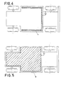
- FIG. 4 illustrates the attachment of a linearly extended electrode to a vehicle underbody
- FIG. 5 illustrates the attachment of an areally extended electrode to a vehicle underbody.
- Fig. 6 illustrates the placement of a spatially extended electrode 10 in a cavity of a vehicle body, e.g. an entry beam 11, the electrode 10 touching the metal parts that delimit the cavity over a large area.
Landscapes
- Chemical & Material Sciences (AREA)
- Engineering & Computer Science (AREA)
- Materials Engineering (AREA)
- Mechanical Engineering (AREA)
- Metallurgy (AREA)
- Organic Chemistry (AREA)
- Prevention Of Electric Corrosion (AREA)
- Buildings Adapted To Withstand Abnormal External Influences (AREA)
Applications Claiming Priority (2)
| Application Number | Priority Date | Filing Date | Title |
|---|---|---|---|
| AT2063/85 | 1985-07-12 | ||
| AT0206385A AT384626B (de) | 1985-07-12 | 1985-07-12 | Vorrichtung zur anwendung des kathodischen korrosionsschutzes an nicht erdverlegten anlagen |
Publications (2)
| Publication Number | Publication Date |
|---|---|
| EP0229115A1 EP0229115A1 (de) | 1987-07-22 |
| EP0229115B1 true EP0229115B1 (de) | 1990-11-28 |
Family
ID=3526986
Family Applications (1)
| Application Number | Title | Priority Date | Filing Date |
|---|---|---|---|
| EP86904027A Expired - Lifetime EP0229115B1 (de) | 1985-07-12 | 1986-07-14 | Vorrichtung zum kathodischen korrosionsschutz von metallteilen |
Country Status (7)
| Country | Link |
|---|---|
| US (1) | US4798658A (ja) |
| EP (1) | EP0229115B1 (ja) |
| JP (1) | JPS63500312A (ja) |
| AT (2) | AT384626B (ja) |
| CA (1) | CA1298568C (ja) |
| DE (1) | DE3675912D1 (ja) |
| WO (1) | WO1987000558A1 (ja) |
Families Citing this family (5)
| Publication number | Priority date | Publication date | Assignee | Title |
|---|---|---|---|---|
| US5167785A (en) * | 1989-10-07 | 1992-12-01 | Mccready David F | Thin electrodes |
| DE10319607B3 (de) * | 2003-05-02 | 2004-10-14 | Saint-Gobain Sekurit Deutschland Gmbh & Co. Kg | Korrosionsschutzschaltung für eine Leiterstruktur auf einer Antennenscheibe, Verfahren zum Betreiben einer aktiven Antennenscheibe und Antennenscheibe für Fahrzeuge |
| US8287285B2 (en) * | 2010-10-22 | 2012-10-16 | Johnson Controls Technology Company | System and method for reducing electromagnetic interference from a conductive interior trim component |
| DE102017131188A1 (de) | 2017-12-22 | 2019-06-27 | KM Innopat GmbH | Korrosionsschutz und Korrosionsschutzüberwachung |
| US20210230752A1 (en) * | 2020-01-24 | 2021-07-29 | Richard L. Klopp | Corrosion Inhibitor Apparatus for Land Vehicles |
Family Cites Families (7)
| Publication number | Priority date | Publication date | Assignee | Title |
|---|---|---|---|---|
| US3498898A (en) * | 1967-07-25 | 1970-03-03 | Ford Motor Co | Method for providing corrosion protection for automobile bodies |
| BE779914R (en) * | 1972-01-14 | 1972-06-16 | Degeest Willy | Cathodic protection for road vehicles - provides effective anti corrosive means for metal bodywork |
| US3957008A (en) * | 1974-03-28 | 1976-05-18 | Mccormick Michael E | Drag reduction of water vehicles using gas created by electrolysis on electrodes attached to the hull |
| US4226694A (en) * | 1976-08-16 | 1980-10-07 | Texas Instruments Incorporated | Cathodic protection system for a motor vehicle |
| DE3226146A1 (de) * | 1982-07-13 | 1984-01-19 | Lebar, Robert, Dipl.-Ing., 4100 Duisburg | Korrosionsschutz |
| AT378207B (de) * | 1983-10-25 | 1985-07-10 | Padinger Reinhard | Elektrisches korrosionsschutzgeraet fuer fahrzeuge |
| FR2555517B1 (fr) * | 1983-11-29 | 1988-04-08 | Citroen Sa | Porte de vehicule a vitre coulissante |
-
1985
- 1985-07-12 AT AT0206385A patent/AT384626B/de not_active IP Right Cessation
-
1986
- 1986-07-09 CA CA000513429A patent/CA1298568C/en not_active Expired - Fee Related
- 1986-07-14 WO PCT/AT1986/000048 patent/WO1987000558A1/de active IP Right Grant
- 1986-07-14 JP JP61503945A patent/JPS63500312A/ja active Pending
- 1986-07-14 AT AT86904027T patent/ATE58758T1/de not_active IP Right Cessation
- 1986-07-14 DE DE8686904027T patent/DE3675912D1/de not_active Expired - Fee Related
- 1986-07-14 US US07/037,352 patent/US4798658A/en not_active Expired - Fee Related
- 1986-07-14 EP EP86904027A patent/EP0229115B1/de not_active Expired - Lifetime
Also Published As
| Publication number | Publication date |
|---|---|
| US4798658A (en) | 1989-01-17 |
| WO1987000558A1 (en) | 1987-01-29 |
| ATE58758T1 (de) | 1990-12-15 |
| ATA206385A (de) | 1987-05-15 |
| CA1298568C (en) | 1992-04-07 |
| EP0229115A1 (de) | 1987-07-22 |
| DE3675912D1 (de) | 1991-01-10 |
| AT384626B (de) | 1987-12-10 |
| JPS63500312A (ja) | 1988-02-04 |
Similar Documents
| Publication | Publication Date | Title |
|---|---|---|
| DE102012221002A1 (de) | Abwinkelbare und/oder abgewinkelte Leiterplattenstruktur mit zumindest zwei Leiterplattenabschnitten und Verfahren zu deren Herstellung | |
| DE2134815B2 (de) | Gehäuseanordnung für elektrische Geräte zur Abschirmung gegen elektrostatische und magnetostatische Strahlen | |
| DE8104954U1 (de) | Elektrische Flachleiterkabelanordnung | |
| DE2731976A1 (de) | Kathodisches schutzsystem fuer metallische oberflaechen | |
| DE2208275A1 (de) | Vorrichtung zum Ermitteln der Ab nutzung einer Flache eines Maschinen elements | |
| DE2736693A1 (de) | Katodische korrosionsschutzanordnung fuer ein fahrzeug | |
| DE102016103439A1 (de) | Kontaktstelle eines Flachleiters | |
| EP0229115B1 (de) | Vorrichtung zum kathodischen korrosionsschutz von metallteilen | |
| DE1258941B (de) | Verfahren zur Herstellung von mehrschichtigen Duennfilmschaltungsplatten | |
| EP0436987B1 (de) | Elektrisches Freileiterseil mit integrierter optischer Nachrichtenleitung | |
| EP0454710B1 (de) | Verfahren zum elektrolytischen abscheiden von metallen auf einer oder beiden seiten von baendern | |
| DE10031906B4 (de) | Verfahren zur Herstellung von Elektroden sowie damit hergestellte Elektroden | |
| DE1904223C3 (de) | Bandförmige Elektrode aus einer elektrisch leitfähigen, Graphit enthaltenden Masse | |
| DE102020103581A1 (de) | Verfahren zur Herstellung eines Leichtmetall-Bauteils, Leichtmetall-Bauteil und Kraftfahrzeug | |
| DE2309191A1 (de) | Korrosionsschutzvorrichtung fuer fahrzeuge, insbesondere automobile | |
| DE3022634A1 (de) | Verfahren und vorrichtung zur raschen bestimmung der korrosionsbestaendigkeit einer elektrophoretischen beschichtung | |
| DE8225078U1 (de) | Verbindungselement in Form einer Schraube und/oder einer Mutter | |
| EP3312848A1 (de) | Verfahren zum herstellen einer flachleiteranordnung | |
| DE3439943A1 (de) | Klemme zur halterung von leiterplatten im galvenikbad | |
| DE2555419C2 (de) | Kathode zur Herstellung von Nickelkörpern | |
| DE1154839B (de) | Dipol-Antennenfeld | |
| DE1024762B (de) | Korrosionsschutzbinde aus Kunststoff- oder Kautschukfolie, insbesondere fuer erdverlegte Rohrleitungen | |
| DE19917286A1 (de) | Verfahren zur Herstellung isolierter Stromschienen insbesondere für Leistungselektronik-Bauelemente und entsprechend isolierte Stromschienen | |
| DE19753097A1 (de) | Korrosionsvermeidung | |
| DE19704138A1 (de) | Verfahren zum Korrosionsschutz und geeignetes Korrosionsschutz-Material für dieses Verfahren |
Legal Events
| Date | Code | Title | Description |
|---|---|---|---|
| PUAI | Public reference made under article 153(3) epc to a published international application that has entered the european phase |
Free format text: ORIGINAL CODE: 0009012 |
|
| 17P | Request for examination filed |
Effective date: 19870309 |
|
| AK | Designated contracting states |
Kind code of ref document: A1 Designated state(s): AT BE CH DE FR GB IT LI LU NL SE |
|
| 17Q | First examination report despatched |
Effective date: 19880923 |
|
| GRAA | (expected) grant |
Free format text: ORIGINAL CODE: 0009210 |
|
| AK | Designated contracting states |
Kind code of ref document: B1 Designated state(s): AT BE CH DE FR GB IT LI LU NL SE |
|
| REF | Corresponds to: |
Ref document number: 58758 Country of ref document: AT Date of ref document: 19901215 Kind code of ref document: T |
|
| REF | Corresponds to: |
Ref document number: 3675912 Country of ref document: DE Date of ref document: 19910110 |
|
| ITF | It: translation for a ep patent filed |
Owner name: MARCHI & MITTLER S.R.L. |
|
| GBT | Gb: translation of ep patent filed (gb section 77(6)(a)/1977) | ||
| ET | Fr: translation filed | ||
| PG25 | Lapsed in a contracting state [announced via postgrant information from national office to epo] |
Ref country code: AT Effective date: 19910714 |
|
| ITTA | It: last paid annual fee | ||
| PGFP | Annual fee paid to national office [announced via postgrant information from national office to epo] |
Ref country code: CH Payment date: 19910925 Year of fee payment: 6 |
|
| PLBE | No opposition filed within time limit |
Free format text: ORIGINAL CODE: 0009261 |
|
| STAA | Information on the status of an ep patent application or granted ep patent |
Free format text: STATUS: NO OPPOSITION FILED WITHIN TIME LIMIT |
|
| 26N | No opposition filed | ||
| PG25 | Lapsed in a contracting state [announced via postgrant information from national office to epo] |
Ref country code: LI Effective date: 19920731 Ref country code: CH Effective date: 19920731 |
|
| REG | Reference to a national code |
Ref country code: CH Ref legal event code: PL |
|
| PGFP | Annual fee paid to national office [announced via postgrant information from national office to epo] |
Ref country code: DE Payment date: 19940609 Year of fee payment: 9 |
|
| PGFP | Annual fee paid to national office [announced via postgrant information from national office to epo] |
Ref country code: FR Payment date: 19940616 Year of fee payment: 9 |
|
| PGFP | Annual fee paid to national office [announced via postgrant information from national office to epo] |
Ref country code: LU Payment date: 19940630 Year of fee payment: 9 |
|
| PGFP | Annual fee paid to national office [announced via postgrant information from national office to epo] |
Ref country code: GB Payment date: 19940712 Year of fee payment: 9 |
|
| EPTA | Lu: last paid annual fee | ||
| PGFP | Annual fee paid to national office [announced via postgrant information from national office to epo] |
Ref country code: SE Payment date: 19940731 Year of fee payment: 9 Ref country code: NL Payment date: 19940731 Year of fee payment: 9 |
|
| PGFP | Annual fee paid to national office [announced via postgrant information from national office to epo] |
Ref country code: BE Payment date: 19940804 Year of fee payment: 9 |
|
| EAL | Se: european patent in force in sweden |
Ref document number: 86904027.9 |
|
| PG25 | Lapsed in a contracting state [announced via postgrant information from national office to epo] |
Ref country code: LU Free format text: LAPSE BECAUSE OF NON-PAYMENT OF DUE FEES Effective date: 19950714 Ref country code: GB Effective date: 19950714 |
|
| PG25 | Lapsed in a contracting state [announced via postgrant information from national office to epo] |
Ref country code: SE Effective date: 19950715 |
|
| PG25 | Lapsed in a contracting state [announced via postgrant information from national office to epo] |
Ref country code: BE Effective date: 19950731 |
|
| BERE | Be: lapsed |
Owner name: D 3 CATHODIC PRODUCTS-KORROSIONSSCHUTZPRODUKTE G. Effective date: 19950731 |
|
| PG25 | Lapsed in a contracting state [announced via postgrant information from national office to epo] |
Ref country code: NL Effective date: 19960201 |
|
| GBPC | Gb: european patent ceased through non-payment of renewal fee |
Effective date: 19950714 |
|
| NLV4 | Nl: lapsed or anulled due to non-payment of the annual fee |
Effective date: 19960201 |
|
| PG25 | Lapsed in a contracting state [announced via postgrant information from national office to epo] |
Ref country code: DE Effective date: 19960402 |
|
| EUG | Se: european patent has lapsed |
Ref document number: 86904027.9 |
|
| PG25 | Lapsed in a contracting state [announced via postgrant information from national office to epo] |
Ref country code: FR Effective date: 19960430 |
|
| REG | Reference to a national code |
Ref country code: FR Ref legal event code: ST |
|
| REG | Reference to a national code |
Ref country code: FR Ref legal event code: ST |
|
| REG | Reference to a national code |
Ref country code: FR Ref legal event code: ST |
|
| PG25 | Lapsed in a contracting state [announced via postgrant information from national office to epo] |
Ref country code: IT Free format text: LAPSE BECAUSE OF NON-PAYMENT OF DUE FEES;WARNING: LAPSES OF ITALIAN PATENTS WITH EFFECTIVE DATE BEFORE 2007 MAY HAVE OCCURRED AT ANY TIME BEFORE 2007. THE CORRECT EFFECTIVE DATE MAY BE DIFFERENT FROM THE ONE RECORDED. Effective date: 20050714 |