EP0228635B2 - Elektronische Uhr - Google Patents
Elektronische Uhr Download PDFInfo
- Publication number
- EP0228635B2 EP0228635B2 EP86117343A EP86117343A EP0228635B2 EP 0228635 B2 EP0228635 B2 EP 0228635B2 EP 86117343 A EP86117343 A EP 86117343A EP 86117343 A EP86117343 A EP 86117343A EP 0228635 B2 EP0228635 B2 EP 0228635B2
- Authority
- EP
- European Patent Office
- Prior art keywords
- solar cell
- cell arrangement
- electronic timepiece
- storage means
- display
- Prior art date
- Legal status (The legal status is an assumption and is not a legal conclusion. Google has not performed a legal analysis and makes no representation as to the accuracy of the status listed.)
- Expired - Lifetime
Links
- 239000004973 liquid crystal related substance Substances 0.000 claims description 11
- 238000003860 storage Methods 0.000 claims description 7
- 239000003990 capacitor Substances 0.000 claims description 6
- 238000005286 illumination Methods 0.000 claims 1
- 230000006870 function Effects 0.000 description 5
- 239000010453 quartz Substances 0.000 description 4
- VYPSYNLAJGMNEJ-UHFFFAOYSA-N silicon dioxide Inorganic materials O=[Si]=O VYPSYNLAJGMNEJ-UHFFFAOYSA-N 0.000 description 4
- 230000000717 retained effect Effects 0.000 description 2
- 230000004888 barrier function Effects 0.000 description 1
- 230000000694 effects Effects 0.000 description 1
- 238000005265 energy consumption Methods 0.000 description 1
- 238000012432 intermediate storage Methods 0.000 description 1
Images

Classifications
-
- G—PHYSICS
- G04—HOROLOGY
- G04C—ELECTROMECHANICAL CLOCKS OR WATCHES
- G04C10/00—Arrangements of electric power supplies in time pieces
- G04C10/02—Arrangements of electric power supplies in time pieces the power supply being a radioactive or photovoltaic source
Definitions
- the invention relates to an electronic watch with a solar cell arrangement and a memory for the electrical energy supplied by the solar cell arrangement, the solar cell arrangement being connected to the memory via a device which prevents a backflow of current from the memory, and with a clock circuit connected to the memory and one of This driven display device and it further relates to an electronic watch with a clock circuit connected to a non-rechargeable battery and with a display device.
- Electronic clocks with a quartz oscillator belong to the prior art and are known, for example, from DE 21 46 776 C2.
- the power requirements of the electronic circuit and the displays have been continuously reduced in recent years.
- Such clocks are usually supplied with energy with the aid of primary batteries.
- Wristwatches that include a rechargeable battery and solar cells for charging are also known.
- Electronic watches with low-voltage capacitors with high capacitance have also recently come onto the market. The capacitors of such watches are charged with solar cells in the dial and guarantee a power reserve of 50 hours. However, this turns out to be too little for the winter season in the Federal Republic of Germany and in geographically similar countries.
- a watch is known from DE 33 37 407 A1, the display device of which is at least partially switched off by a photoresistor when the ambient brightness is insufficient, so that the overall power reserve of the watch is increased.
- the invention has for its object to provide an electronic watch of the type mentioned, which is characterized by a very high power reserve.
- the fact that the power supply is separated from the watch electronics and the display results in substantial energy savings and thus a higher power reserve.
- the display device which has the greatest energy requirement, in particular in the case of larger clocks, is operated directly via the solar cells of the solar cell arrangement without intermediate storage. This ensures that the display device is only in operation when the lighting is also sufficient for reading it.
- the clock circuit is operated with an energy store, either a battery or a capacitor, which ensures that the time function is retained.
- a mechanical pointer mechanism can also be used.
- a stepper motor is provided which is controlled in such a way that, after it has come to a standstill overnight, it brings the pointers of the pointer mechanism into the correct position when illuminated.
- the watch can also be equipped with an electronic calendar.
- the solar cell arrangement is used exclusively for feeding the display device and not for recharging the battery.
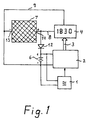
- the electronic watch shown in FIG. 1 has a quartz oscillator 1, which serves as a frequency reference for a watch circuit 2, by means of which the time keeping function of the electronic watch is ensured.
- the clock circuit 2 are assigned actuation switches, not shown in the drawing, which allow the clock circuit 2 to be set to a specific time, a specific date, a specific day of the week, a wake-up time or the like.
- actuation switches not shown in the drawing, which allow the clock circuit 2 to be set to a specific time, a specific date, a specific day of the week, a wake-up time or the like.
- components for stopwatch functions that may be present and acoustic displays for a time and / or alarm times are also not shown. It is self-evident to the person skilled in the art that the clock circuit 2 can be equipped with such additional circuits or functions.
- the clock circuit 2 is connected via a line 3 to a display device, which in the embodiment shown in FIG. 1 is a liquid crystal display 4 and in the embodiment of the invention shown in FIG. 2 is a mechanical pointer mechanism 5 with hands 10 and 11.
- a stepping motor with control electronics is assigned to the mechanical pointer mechanism 5 shown schematically in FIG. 2.
- the quartz oscillator 1 and the clock circuit 2 are supplied with electrical energy via an electrical memory 6.
- the electrical storage 6 is preferably a rechargeable battery or a low-voltage capacitor with a high capacity.
- a solar cell arrangement 7 shown in FIGS. 1 and 2 is connected via lines 8 and 9 to the liquid crystal display 4 or the mechanical pointer mechanism 5 in order to supply the liquid crystal display 4 or the pointer mechanism 5 with electrical energy.
- the liquid crystal display 4 or the pointer mechanism 5 is operated directly via the solar cell arrangement 7 without interposing the electrical memory 6. Since the display device has a greater energy requirement, in particular in the case of larger clocks, the power supply for the clock electronics and the display achieve substantial energy savings because the display in the form of the liquid crystal display 4 or the mechanical pointer mechanism 5 is only in operation when the lighting is also sufficient for reading.
- the clock circuit 2 is operated with the aid of the electrical memory 6, which can either be a battery or a capacitor, ensuring that the time function of the clock circuit 2 is retained.
- a diode 12 is provided in the exemplary embodiments shown in FIGS. 1 and 2.
- the diode 12 is connected with its anode to the line 8 and with its cathode to the positive pole of the electrical store 6, in particular an accumulator. This polarity ensures that for charging the memory 6 electrons from the negative pole 13 of the solar cell arrangement 7 can reach the negative pole of the electrical memory 6 and from the positive pole of the electrical memory 6 via the diode 12 to the positive pole 14 of the solar cell 7.
- the electrical store 6 is charged or recharged.
- the store 6 is discharged via the diode 12
- the diode 12 thus has the effect that the electrical memory 6 charged by the solar cell arrangement 7 supplies only the electronics, that is to say in particular the quartz oscillator 1 and the clock circuit 2, and that the display device, in particular the liquid crystal display 4 or the mechanical pointer mechanism 5 with a stepping motor, without Memory is fed directly from the solar cell arrangement 7.
- a non-rechargeable battery is used as the energy source instead of an electrical store 6, for example in the form of a rechargeable battery.
- the solar cell arrangement 7 is used in such an electronic watch exclusively for feeding the display device, in particular the liquid crystal display 4 or the mechanical pointer mechanism 5 and not for loading the memory 6. Therefore, in the last-mentioned exemplary embodiment there is no connection between the line 8 and the non-rechargeable battery is provided so that the diode 12 is omitted.
Landscapes
- Engineering & Computer Science (AREA)
- Power Engineering (AREA)
- Physics & Mathematics (AREA)
- General Physics & Mathematics (AREA)
- Electromechanical Clocks (AREA)
- Organic Low-Molecular-Weight Compounds And Preparation Thereof (AREA)
- Polysaccharides And Polysaccharide Derivatives (AREA)
- Mechanical Treatment Of Semiconductor (AREA)
Description
- Die Erfindung betrifft eine elektronische Uhr mit einer Solarzellenanordnung und einem Speicher für die von der Solarzellenanordnung gelieferte elektrische Energie, wobei die Solarzellenanordnung über eine einen Stromrückfluß aus dem Speicher verhindernde Einrichtung mit dem Speicher verbunden ist, und mit einem an den Speicher angeschlossenen Uhrenschaltkreis sowie einer von diesem angesteuerten Anzeigevorrichtung und sie betrifft ferner eine elektronische Uhr mit einem an eine nichtwiederaufladbare Batterie angeschlossenen Uhrenschaltkreis sowie mit einer Anzeigevorrichtung.
- Elektronische Uhren mit Quarzoszillator gehören zum Stand der Technik und sind beispielsweise aus der DE 21 46 776 C2 bekannt. Der Leistungsbedarf der elektronischen Schaltung und der Displays wurde in den vergangenen Jahren laufend verringert. Üblicherweise werden solche Uhren mit Hilfe von Primärbatterien mit Energie versorgt. Armbanduhren, die eine wiederaufladbare Batterie und Solarzellen zur Aufladung enthalten, sind ebenfalls bekannt. In jüngster Zeit sind auch elektronische Uhren mit Niedervoltkondensatoren hoher Kapazität auf den Markt, gekommen. Die Kondensatoren solcher Uhren werden mit im Zifferblatt befindlichen Solarzellen aufgeladen und gewährleisten eine Gangreserve von 50 Stunden. Dies erweist sich jedoch als zu wenig für die Wintersaison in der Bundesrepublik Deutschland und in geographisch ähnlich gelegenen Ländern.
- Aus den Funkschau Arbeitsblättern, in Funkschau 24, S. 64 ff (1985) ist ein elektrischer Verbraucher nach dem Oberbegriff des Anspruchs 1 bekannt, wenn als spezieller elektrischer Verbraucher eine Uhrenschaltung mit einer Anzeigevorrichtung verwendet wird. Ein elektrischer Verbraucher, insbesondere eine Uhr, nach dieser Druckschrift weist keine hohe Gangreserve auf.
- Aus der DE 33 37 407 A1 ist eine Uhr bekannt, deren Anzeigevorrichtung durch einen Photowiderstand dann zumindest teilweise abgeschaltet wird, wenn die Umgebungshelligkeit ungenügend ist, so daß die Gangreserve der Uhr insgesamt erhöht wird.
- Ausgehend von diesem Stand der Technik liegt der Erfindung die Aufgabe zugrunde, eine elektronische Uhr der eingangs genannten Art zu schaffen, die sich durch eine sehr hohe Gangreserve auszeichnet.
- Diese Aufgabe wird für eine elektronische Uhr gemäß dem eingangs genannten Oberbegriff von Anspruch 1 bzw. Anspruch 9 erfindungsgemäß dadurch gelöst, daß die Anzeigevorrichtung zur unmittelbaren Stromversorgung direkt an die Solarzellenanordnung angeschlossen ist.
- Dadurch, daß die Stromversorgung von der Uhrenelektronik und vom Display getrennt wird, ergibt sich eine wesentliche Energieeinsparung und damit eine höhere Gangreserve. Die Anzeigevorrichtung, die insbesondere bei größeren Uhren den größten Energiebedarf hat, wird direkt über die Solarzellen der Solarzellenanordnung ohne zwischengeschaltete Speicher betrieben. Dadurch wird erreicht, daß die Anzeigeeinrichtung nur in Betrieb ist, wenn die Beleuchtung auch zu deren Ablesung ausreicht. Der Uhrenschaltkreis wird dagegen mit einem Energiespeicher, entweder einer Batterie oder einem Kondensator betrieben, wodurch gewährleistet wird, daß die Zeitfunktion erhalten bleibt. Statt eines Flüssigkristalldisplays, das wegen des geringeren Energieverbrauchs vorzuziehen ist, kann auch ein mechanisches Zeigerwerk eingesetzt werden. In diesem Fall ist ein Schrittmotor vorgesehen, der so angesteuert ist, daß er nach dem Stillstand über Nacht die Zeiger des Zeigerwerks bei Beleuchtung in die richtige Position bringt. Selbstverständlich kann die Uhr auch mit einem elektronischen Kalender ausgerüstet sein.
- Wenn statt einer wiederaufladbaren Batterie eine nichtwiederaufladbare Batterie verwendet wird, dient die Solarzellenanordnung ausschließlich zur Speisung der Anzeigeeinrichtung und nicht zum Nachladen der Batterie.
- Nachfolgend wird die Erfindung anhand der Zeichnung näher beschrieben. Es zeigen:
- Fig. 1
- ein erstes Ausführungsbeispiel der Erfindung mit einem Flüssigkristalldisplay und
- Fig. 2
- ein weiteres Ausführungsbeispiel der Erfindung mit einem mechanischen Zeigerwerk.
- Die in Fig. 1 dargestellte elektronische Uhr verfügt über einen Quarzoszillator 1, der als Frequenzreferenz für einen Uhrenschaltkreis 2 dient, durch den die Zeithaltefunktion der elektronischen Uhr gewährleistet wird.
- Dem Uhrenschaltkreis 2 sind in der Zeichnung nicht dargestellte Betätigungsschalter zugeordnet, die es gestatten den Uhrenschaltkreis 2 auf eine bestimmte Uhrzeit, ein bestimmtes Datum, einen bestimmten Wochentag, eine Weckzeit oder dergleichen zu setzen. Zur Vereinfachung der Zeichnung sind weiterhin Bauelemente für gegebenenfalls vorhandene Stopuhrenfunktionen sowie akustische Anzeigen für eine Uhrzeit und/oder Alarmzeiten nicht dargestellt. Für den Fachmann ist es selbstverständlich, daß der Uhrenschaltkreis 2 mit derartigen zusätzlichen Schaltkreisen oder Funktionen ausgestattet sein kann.
- Der Uhrenschaltkreis 2 ist über eine Leitung 3 mit einer Anzeigevorrichtung verbunden, die bei dem in Fig. 1 dargestellten Ausführungsbeispiel ein Flüssigkristalldisplay 4 und bei dem in Fig. 2 dargestellten Ausführungsbeispiel der Erfindung ein mechanisches Zeigerwerk 5 mit Zeigern 10 und 11 ist.
- Dem in Fig. 2 schematisch dargestellten mechanischen Zeigerwerk 5 ist ein Schrittmotor mit einer Ansteuerelektronik zugeordnet.
- Wie man in den Figuren 1 und 2 erkennt, werden der Quarzoszillator 1 und der Uhrenschaltkreis 2 über einen elektrischen Speicher 6 mit elektrischer Energie versorgt. Der elektrische Speicher 6 ist vorzugsweise eine wiederaufladbare Batterie oder ein Niedervoltkondensator mit hoher Kapazität.
- Eine in den Figuren 1 und 2 dargestellte Solarzellenanordnung 7 ist über Leitungen 8 und 9 mit dem Flüssigkristalldisplay 4, bzw. dem mechanischen Zeigerwerk 5 verbunden, um das Flüssigkristalldisplay 4 bzw. das Zeigerwerk 5 mit elektrischer Energie zu versorgen. Auf diese Weise wird das Flüssigkristalldisplay 4 bzw. das Zeigerwerk 5, direkt über die Solarzellenanordnung 7 ohne Zwischenschaltung des elektrischen Speichers 6 betrieben. Da die Anzeigevorrichtung insbesondere bei größeren Uhren einen größeren Energiebedarf hat, wird durch Trennen der Stromversorgung für die Uhrenelektronik und das Display eine wesentliche Energieeinsparung erreicht, weil das Display in Gestalt des Flüssigkristalldisplays 4 oder des mechanischen Zeigerwerks 5 nur dann in Betrieb ist, wenn die Beleuchtung auch zur Ablesung ausreicht.
- Der Uhrenschaltkreis 2 wird dagegen mit Hilfe des elektrischen Speichers 6, der entweder eine Batterie oder ein Kondensator sein kann, betrieben wobei gewährleistet wird, daß die Zeitfunktion des Uhrenschaltkreises 2 erhalten bleibt.
- Wenn ein mechanisches Zeigerwerk 5 gemäß Fig. 2 mit einem zugeordneten Schrittmotor verwendet wird, ist es erforderlich, nach einem Stillstand über Nacht die Zeiger 10, 11 bei Beleuchtung in die richtige, der vom Uhrenschaltkreis 2 über die Leitung 3 mitgeteilten Uhrzeit zugeordnete Position zu bringen. Dies geschieht bei dem in Fig. 2 schematisch dargestellen Ausführungsbeispiel mit einer Ansteuerelektronik des Schrittmotors, die beim Auftreten einer ausreichend hohen Spannung an den Leitungen 8 und 9 den Schrittmotor und die Zeiger 10 und 11 solange nachführt, bis deren Position mit der über die Leitung 3 gelieferten Zeit übereinstimmt.
- Zur Trennung der Stromversorgung der Uhrenelektronik und des Displays ist bei den in den Fig. 1 und 2 dargestellten Ausführungsbeispielen eine Diode 12 vorgesehen. Bei der in der Zeichnung beispielsweise eingetragenen Polarität für die Solarzellenanordnung 7 und den elektrischen Speicher 6 ist die Diode 12 mit ihrer Anode mit der Leitung 8 und mit ihrer Kathode mit dem Pluspol des elektrischen Speichers 6, insbesondere eines Akkumulators verbunden. Durch diese Polung wird erreicht, daß zum Laden des Speichers 6 Elektronen vom Minuspol 13 der Solarzellenanordnung 7 zum Minuspol des elektrischen Speichers 6 und vom Pluspol des elektrischen Speichers 6 über die Diode 12 zum Pluspol 14 der Solarzelle 7 gelangen können. Wenn die zwischen dem Minuspol 13 und dem Pluspol 14 vorhandene Spannung der Solarzellenanordnung 7 die Spannung des elektrischen Speichers 6 um mehr als die Schwellenspannung der Diode 12 übersteigt, erfolgt ein Aufladen oder Nachladen des elektrischen Speichers 6. Ein Entladen des Speichers 6 über die Diode 12 zum Speisen des Flüssigkristalldisplays 4 oder des mechanischen Zeigerwerks 5 mit elektrischem Strom ist jedoch nicht möglich, weil für diesen Stromkreis durch die Diode 12 eine Sperre gebildet ist. Die Diode 12 bewirkt somit, daß der von der Solarzellenanordnung 7 geladene elektrische Speicher 6 nur die Elektronik, das heißt insbesondere den Quarzoszillator 1 und den Uhrenschaltkreis 2 versorgt und daß die Anzeigeeinrichtung, insbesondere das Flüssigkristalldisplay 4 oder das mechanische Zeigerwerk 5 mit einem Schrittmotor, ohne Speicher direkt von der Solarzellenanordnung 7 gespeist ist.
- Bei einem dritten, in der Zeichnung nicht dargestellten Ausführungsbeispiel der Erfindung wird als Energiequelle statt eines elektrischen Speichers 6, beispielsweise in der Form einer wiederaufladbaren Batterie eine nichtwiederaufladbare Batterie verwendet. Aus diesem Grunde dient die Solarzellenanordnung 7 bei einer solchen elektronischen Uhr ausschließlich zum Speisen der Anzeigeeinrichtung, insbesondere des Flüssigkristalldisplays 4 oder des mechanischen Zeigerwerks 5 und nicht zum Laden des Speichers 6. Deswegen ist bei dem zuletzt erwähnten Ausführungsbeispiel keine Verbindung zwischen der Leitung 8 und der nichtaufladbaren Batterie vorgesehen, so daß die Diode 12 entfällt.
Claims (9)
- Elektronische Uhr mit einer Solarzellenanordnung (7) und einem Speicher (6) für die von der Solarzellenanordnung (7) gelieferte elektrische Energie, wobei die Solarzellenanordnung (7) über eine einen Stromrückfluß aus dem Speicher (6) verhindernde Einrichtung (12) mit dem Speicher (6) verbunden ist, und mit einem an den Speicher (6) angeschlossenen Uhrenschaltkreis sowie einer von diesem angesteuerten Anzeigevorrichtung (4, 5), dadurch gekennzeichnet, daß die Anzeigevorrichtung (4, 5) zur unmittelbaren Stromversorgung direkt an die Solarzellenanordnung (7) angeschlossen ist.
- Elektronische Uhr nach Anspruch 1, dadurch gekennzeichnet, daß die Einrichtung eine in Ladestromrichtung durchlässig gepolte Diode (12) ist.
- Elektronische Uhr nach Anspruch 1 oder Anspruch 2, dadurch gekennzeichnet, daß der Speicher (6) eine wiederaufladbare Batterie ist.
- Elektronische Uhr nach Anspruch 1 oder Anspruch 2, dadurch gekennzeichnet, daß der Speicher (6) ein Kondensator ist.
- Elektronische Uhr nach einem der Ansprüche 1 bis 4, dadurch gekennzeichnet, daß die Anzeigevorrichtung ein Flüssigkristalldisplay (4) ist.
- Elektronische Uhr nach einem der Ansprüche 1 bis 5, dadurch gekennzeichnet, daß die Anzeigevorrichtung ein mechanisches Zeigerwerk (5) ist, das bei Einsatz der Beleuchtung in die der Uhrzeit zugeordnete korrekte Position bewegbar ist.
- Elektronische Uhr nach Anspruch 6, dadurch gekennzeichnet, daß das Zeigerwerk (10, 11) über einen Schrittmotor angetrieben ist.
- Elektronische Uhr nach einem der vorstehenden Ansprüche, dadurch gekennzeichnet, daß zusätzlich zur Tageszeit auch Zusatzinformationen wie Daten, Jahreszahl und sonstige Kalenderinformationen anzeigbar sind.
- Elektronische Uhr mit einem an eine nichtwiederaufladbare Batterie angeschlossenen Uhrenschaltkreis sowie mit einer Anzeigevorrichtung, dadurch gekennzeichnet, daß die Anzeigevorrichtung (4, 5) an eine Solarzellenanordnung (7) angeschlossen ist.
Priority Applications (1)
| Application Number | Priority Date | Filing Date | Title |
|---|---|---|---|
| AT86117343T ATE65334T1 (de) | 1986-01-10 | 1986-12-12 | Elektronische uhr. |
Applications Claiming Priority (2)
| Application Number | Priority Date | Filing Date | Title |
|---|---|---|---|
| DE3600515 | 1986-01-10 | ||
| DE3600515A DE3600515C1 (de) | 1986-01-10 | 1986-01-10 | Elektronische Uhr |
Publications (4)
| Publication Number | Publication Date |
|---|---|
| EP0228635A2 EP0228635A2 (de) | 1987-07-15 |
| EP0228635A3 EP0228635A3 (en) | 1989-10-25 |
| EP0228635B1 EP0228635B1 (de) | 1991-07-17 |
| EP0228635B2 true EP0228635B2 (de) | 1995-10-18 |
Family
ID=6291622
Family Applications (1)
| Application Number | Title | Priority Date | Filing Date |
|---|---|---|---|
| EP86117343A Expired - Lifetime EP0228635B2 (de) | 1986-01-10 | 1986-12-12 | Elektronische Uhr |
Country Status (5)
| Country | Link |
|---|---|
| US (1) | US4763310A (de) |
| EP (1) | EP0228635B2 (de) |
| JP (1) | JPS62203085A (de) |
| AT (1) | ATE65334T1 (de) |
| DE (2) | DE3600515C1 (de) |
Families Citing this family (12)
| Publication number | Priority date | Publication date | Assignee | Title |
|---|---|---|---|---|
| DE8718063U1 (de) * | 1987-03-11 | 1993-03-25 | Junghans Uhren GmbH, 7230 Schramberg | Autonome Funkuhr |
| KR910008218B1 (ko) * | 1989-11-30 | 1991-10-12 | 삼성전자 주식회사 | 비디오 프린터의 칼라 기록장치 |
| DE4314003A1 (de) * | 1993-04-26 | 1994-10-27 | Schwerdtle & Schantz Gmbh | Zeitkontrollvorrichtung |
| GB2343540A (en) * | 1998-11-06 | 2000-05-10 | Tacktick Ltd | Solar powered display |
| US6288979B1 (en) * | 2000-04-06 | 2001-09-11 | Moneray International Ltd. | Solar-driven eternity clock |
| TWI224722B (en) * | 2000-05-19 | 2004-12-01 | Asulab Sa | Electronic device for generating and displaying an item of information |
| US6838994B2 (en) * | 2001-10-26 | 2005-01-04 | Koninklijke Philips Electronics N.V. | Adaptive alarm system |
| US7615962B1 (en) | 2005-03-04 | 2009-11-10 | World Factory, Inc. | Solar-powered thermometer and clock |
| JP2013152140A (ja) * | 2012-01-25 | 2013-08-08 | Seiko Instruments Inc | 電子時計 |
| JP2013156159A (ja) * | 2012-01-30 | 2013-08-15 | Seiko Instruments Inc | 電子時計 |
| US20140159638A1 (en) * | 2012-08-19 | 2014-06-12 | EnergyBionics, LLC | Portable energy harvesting, storing, and charging device |
| US9501040B2 (en) * | 2014-10-01 | 2016-11-22 | William J. McNulty, Jr. | Appliance or light timer including rechargeable back-up battery and external charger |
Family Cites Families (15)
| Publication number | Priority date | Publication date | Assignee | Title |
|---|---|---|---|---|
| CH373701A (de) * | 1961-02-06 | 1964-01-15 | Heno Watch S A | Lichtelektrisch betriebene Uhr |
| DE1782185A1 (de) * | 1968-07-29 | 1971-07-29 | Kemper Kate | Vorrichtung zum Wirken von Teigstuecken |
| JPS569674B1 (de) * | 1970-09-18 | 1981-03-03 | ||
| US3928960A (en) * | 1973-02-06 | 1975-12-30 | Time Computer | Combination wristwatch and calculator |
| GB1481024A (en) * | 1974-07-15 | 1977-07-27 | Suisse Horlogerie | Battery powered electronic timepiece with voltage regulation |
| CH1181974A4 (de) * | 1974-08-30 | 1977-06-15 | ||
| JPS51121365A (en) * | 1975-04-17 | 1976-10-23 | Seiko Epson Corp | Electric clock |
| US4015420A (en) * | 1976-05-03 | 1977-04-05 | Hughes Aircraft Company | Battery select circuitry and level translator for a digital watch |
| JPS5428176A (en) * | 1977-08-04 | 1979-03-02 | Seiko Instr & Electronics Ltd | Electronic watch |
| US4234947A (en) * | 1977-12-20 | 1980-11-18 | Citizen Watch Co., Ltd. | Solar battery powered timepiece |
| DE2918064A1 (de) * | 1978-05-08 | 1979-11-22 | Ebauches Sa | Vorrichtung zum laden eines akkumulators durch eine quelle elektrischer energie, insbesondere fuer eine elektronische uhr |
| DE3115682A1 (de) * | 1981-04-18 | 1982-11-04 | Varta Batterie Ag, 3000 Hannover | Batteriebetriebenes elektronisches geraet mit sicherung der spannungsversorgung fuer teilfunktionen |
| DE3337407A1 (de) * | 1983-10-14 | 1985-04-25 | Diehl GmbH & Co, 8500 Nürnberg | Messeinrichtung mit einer passiven anzeigevorrichtung |
| JPH0792506B2 (ja) * | 1984-11-21 | 1995-10-09 | セイコーエプソン株式会社 | 電子時計 |
| CH665081GA3 (de) * | 1985-10-11 | 1988-04-29 |
-
1986
- 1986-01-10 DE DE3600515A patent/DE3600515C1/de not_active Expired - Fee Related
- 1986-12-12 EP EP86117343A patent/EP0228635B2/de not_active Expired - Lifetime
- 1986-12-12 DE DE8686117343T patent/DE3680310D1/de not_active Expired - Fee Related
- 1986-12-12 AT AT86117343T patent/ATE65334T1/de not_active IP Right Cessation
-
1987
- 1987-01-05 US US07/000,399 patent/US4763310A/en not_active Expired - Fee Related
- 1987-01-07 JP JP62000640A patent/JPS62203085A/ja active Pending
Also Published As
| Publication number | Publication date |
|---|---|
| DE3680310D1 (de) | 1991-08-22 |
| US4763310A (en) | 1988-08-09 |
| EP0228635A2 (de) | 1987-07-15 |
| JPS62203085A (ja) | 1987-09-07 |
| ATE65334T1 (de) | 1991-08-15 |
| EP0228635B1 (de) | 1991-07-17 |
| DE3600515C1 (de) | 1993-05-13 |
| EP0228635A3 (en) | 1989-10-25 |
Similar Documents
| Publication | Publication Date | Title |
|---|---|---|
| EP0228635B2 (de) | Elektronische Uhr | |
| DE2122683A1 (de) | Uhr, deren Anzeigeeinrichtung mindestens eine Flüssigkristall-Zelle aufweist | |
| DE2821619C3 (de) | Elektronische Uhr mit Analoganzeige-Zeigerwerk und Flüssigkristall-Anzeigeeinheit | |
| DE19780948B4 (de) | Kombinierte elektronische Uhr | |
| DE3524290C2 (de) | ||
| DE60031080T2 (de) | Zeitgebervorrichtung und Verfahren um diese zu kontrollieren | |
| DE2165421B2 (de) | Uhr mit einer Flüssigkristall-Anzeigeeinrichtung | |
| DE2452687A1 (de) | Schaltvorrichtung fuer eine elektronische uhr mit elektrooptischer anzeige | |
| DE2206102C2 (de) | Armbanduhr o.dgl. | |
| DE2311508A1 (de) | Elektrooptische anzeige fuer elektronische uhren | |
| DE2618863C3 (de) | Elektronische Kleinuhr mit einer digitalen optischen Anzeigeeinrichtung | |
| EP0285838B1 (de) | Autonome Funkuhr | |
| CH524973A (de) | Verfahren zum Einführen und Aufziehen von Reissverschlussschiebern auf fortlaufende, gekuppelte Reissverschlussstreifen | |
| DE2442394B2 (de) | Vollelektronische uhr | |
| DE69827362T2 (de) | Uhr mit detektions- und sparvorrichtungen im falle von nicht ausreichender energieversorgung | |
| DE3702993A1 (de) | Quarzuhr | |
| DE3115682A1 (de) | Batteriebetriebenes elektronisches geraet mit sicherung der spannungsversorgung fuer teilfunktionen | |
| DE1673798A1 (de) | Elektrischer Zeitmesser | |
| CH671485A5 (en) | Power supply circuitry combining solar cell and sec. cell battery - charges lithium cells with capacitor for short duration back-up to overcome recharge delay after long dark periods | |
| DE69001343T2 (de) | Elektronische Zeitmessvorrichtung. | |
| DE1673798C (de) | Elektrischer Zeitmesser mit einem durch eine Solar- oder Photozelle aufladbaren Akkumulator | |
| DE2734721A1 (de) | Batteriebetriebene elektronische uhr | |
| DE2553015A1 (de) | Quarz-gesteuerte uhr mit fluessig- kristall-anzeige | |
| DE1928878A1 (de) | Zeitmessinstrument | |
| DE2640483A1 (de) | Elektronische uhr |
Legal Events
| Date | Code | Title | Description |
|---|---|---|---|
| PUAI | Public reference made under article 153(3) epc to a published international application that has entered the european phase |
Free format text: ORIGINAL CODE: 0009012 |
|
| AK | Designated contracting states |
Kind code of ref document: A2 Designated state(s): AT BE CH DE ES FR GB GR IT LI NL SE |
|
| PUAL | Search report despatched |
Free format text: ORIGINAL CODE: 0009013 |
|
| AK | Designated contracting states |
Kind code of ref document: A3 Designated state(s): AT BE CH DE ES FR GB GR IT LI NL SE |
|
| 17P | Request for examination filed |
Effective date: 19890928 |
|
| 17Q | First examination report despatched |
Effective date: 19901001 |
|
| GRAA | (expected) grant |
Free format text: ORIGINAL CODE: 0009210 |
|
| AK | Designated contracting states |
Kind code of ref document: B1 Designated state(s): AT BE CH DE ES FR GB GR IT LI NL SE |
|
| PG25 | Lapsed in a contracting state [announced via postgrant information from national office to epo] |
Ref country code: GR Free format text: LAPSE BECAUSE OF FAILURE TO SUBMIT A TRANSLATION OF THE DESCRIPTION OR TO PAY THE FEE WITHIN THE PRESCRIBED TIME-LIMIT Effective date: 19910717 Ref country code: SE Effective date: 19910717 Ref country code: BE Effective date: 19910717 |
|
| REF | Corresponds to: |
Ref document number: 65334 Country of ref document: AT Date of ref document: 19910815 Kind code of ref document: T |
|
| ET | Fr: translation filed | ||
| REF | Corresponds to: |
Ref document number: 3680310 Country of ref document: DE Date of ref document: 19910822 |
|
| GBT | Gb: translation of ep patent filed (gb section 77(6)(a)/1977) | ||
| ITF | It: translation for a ep patent filed | ||
| PG25 | Lapsed in a contracting state [announced via postgrant information from national office to epo] |
Ref country code: AT Effective date: 19911231 |
|
| PLBI | Opposition filed |
Free format text: ORIGINAL CODE: 0009260 |
|
| 26 | Opposition filed |
Opponent name: DIEHL GMBH & CO. Effective date: 19920415 |
|
| NLR1 | Nl: opposition has been filed with the epo |
Opponent name: DIEHL GMBH & CO. |
|
| PUAH | Patent maintained in amended form |
Free format text: ORIGINAL CODE: 0009272 |
|
| STAA | Information on the status of an ep patent application or granted ep patent |
Free format text: STATUS: PATENT MAINTAINED AS AMENDED |
|
| 27A | Patent maintained in amended form |
Effective date: 19951018 |
|
| AK | Designated contracting states |
Kind code of ref document: B2 Designated state(s): AT BE CH DE ES FR GB GR IT LI NL SE |
|
| GBTA | Gb: translation of amended ep patent filed (gb section 77(6)(b)/1977) |
Effective date: 19951018 |
|
| REG | Reference to a national code |
Ref country code: CH Ref legal event code: AEN Free format text: AUFRECHTERHALTUNG DES PATENTES IN GEAENDERTER FORM |
|
| ET3 | Fr: translation filed ** decision concerning opposition | ||
| NLR2 | Nl: decision of opposition | ||
| NLR3 | Nl: receipt of modified translations in the netherlands language after an opposition procedure | ||
| ITF | It: translation for a ep patent filed | ||
| PG25 | Lapsed in a contracting state [announced via postgrant information from national office to epo] |
Ref country code: ES Free format text: LAPSE BECAUSE OF FAILURE TO SUBMIT A TRANSLATION OF THE DESCRIPTION OR TO PAY THE FEE WITHIN THE PRESCRIBED TIME-LIMIT Effective date: 19960129 |
|
| PGFP | Annual fee paid to national office [announced via postgrant information from national office to epo] |
Ref country code: GB Payment date: 19961129 Year of fee payment: 11 |
|
| PGFP | Annual fee paid to national office [announced via postgrant information from national office to epo] |
Ref country code: DE Payment date: 19961210 Year of fee payment: 11 |
|
| PGFP | Annual fee paid to national office [announced via postgrant information from national office to epo] |
Ref country code: FR Payment date: 19961217 Year of fee payment: 11 |
|
| PGFP | Annual fee paid to national office [announced via postgrant information from national office to epo] |
Ref country code: CH Payment date: 19961220 Year of fee payment: 11 |
|
| PGFP | Annual fee paid to national office [announced via postgrant information from national office to epo] |
Ref country code: NL Payment date: 19961223 Year of fee payment: 11 |
|
| PG25 | Lapsed in a contracting state [announced via postgrant information from national office to epo] |
Ref country code: GB Free format text: LAPSE BECAUSE OF NON-PAYMENT OF DUE FEES Effective date: 19971212 |
|
| PG25 | Lapsed in a contracting state [announced via postgrant information from national office to epo] |
Ref country code: LI Free format text: LAPSE BECAUSE OF NON-PAYMENT OF DUE FEES Effective date: 19971231 Ref country code: CH Free format text: LAPSE BECAUSE OF NON-PAYMENT OF DUE FEES Effective date: 19971231 Ref country code: FR Free format text: THE PATENT HAS BEEN ANNULLED BY A DECISION OF A NATIONAL AUTHORITY Effective date: 19971231 |
|
| PG25 | Lapsed in a contracting state [announced via postgrant information from national office to epo] |
Ref country code: NL Free format text: LAPSE BECAUSE OF NON-PAYMENT OF DUE FEES Effective date: 19980701 |
|
| GBPC | Gb: european patent ceased through non-payment of renewal fee |
Effective date: 19971212 |
|
| REG | Reference to a national code |
Ref country code: CH Ref legal event code: PL |
|
| NLV4 | Nl: lapsed or anulled due to non-payment of the annual fee |
Effective date: 19980701 |
|
| PG25 | Lapsed in a contracting state [announced via postgrant information from national office to epo] |
Ref country code: DE Free format text: LAPSE BECAUSE OF NON-PAYMENT OF DUE FEES Effective date: 19980901 |
|
| REG | Reference to a national code |
Ref country code: FR Ref legal event code: ST |
|
| PG25 | Lapsed in a contracting state [announced via postgrant information from national office to epo] |
Ref country code: IT Free format text: LAPSE BECAUSE OF NON-PAYMENT OF DUE FEES;WARNING: LAPSES OF ITALIAN PATENTS WITH EFFECTIVE DATE BEFORE 2007 MAY HAVE OCCURRED AT ANY TIME BEFORE 2007. THE CORRECT EFFECTIVE DATE MAY BE DIFFERENT FROM THE ONE RECORDED. Effective date: 20051212 |
|
| PG25 | Lapsed in a contracting state [announced via postgrant information from national office to epo] |
Ref country code: ES Free format text: LAPSE BECAUSE OF FAILURE TO SUBMIT A TRANSLATION OF THE DESCRIPTION OR TO PAY THE FEE WITHIN THE PRESCRIBED TIME-LIMIT Effective date: 19911231 |