EP0228494A1 - Laundry dryer framework - Google Patents
Laundry dryer framework Download PDFInfo
- Publication number
- EP0228494A1 EP0228494A1 EP86100149A EP86100149A EP0228494A1 EP 0228494 A1 EP0228494 A1 EP 0228494A1 EP 86100149 A EP86100149 A EP 86100149A EP 86100149 A EP86100149 A EP 86100149A EP 0228494 A1 EP0228494 A1 EP 0228494A1
- Authority
- EP
- European Patent Office
- Prior art keywords
- arms
- laundry
- mast
- guide elements
- laundry rack
- Prior art date
- Legal status (The legal status is an assumption and is not a legal conclusion. Google has not performed a legal analysis and makes no representation as to the accuracy of the status listed.)
- Granted
Links
- 230000000284 resting effect Effects 0.000 claims description 2
- 239000000969 carrier Substances 0.000 claims 1
- 238000004873 anchoring Methods 0.000 description 3
- 238000010276 construction Methods 0.000 description 3
- 238000011109 contamination Methods 0.000 description 3
- 238000006073 displacement reaction Methods 0.000 description 2
- 230000001154 acute effect Effects 0.000 description 1
- XAGFODPZIPBFFR-UHFFFAOYSA-N aluminium Chemical compound [Al] XAGFODPZIPBFFR-UHFFFAOYSA-N 0.000 description 1
- 229910052782 aluminium Inorganic materials 0.000 description 1
- 230000001419 dependent effect Effects 0.000 description 1
- 238000011161 development Methods 0.000 description 1
- 230000018109 developmental process Effects 0.000 description 1
- 230000005484 gravity Effects 0.000 description 1
- 230000007257 malfunction Effects 0.000 description 1
- 238000004519 manufacturing process Methods 0.000 description 1
- 238000000034 method Methods 0.000 description 1
- 230000000750 progressive effect Effects 0.000 description 1
- 230000002441 reversible effect Effects 0.000 description 1
- 238000007665 sagging Methods 0.000 description 1
Images


Classifications
-
- D—TEXTILES; PAPER
- D06—TREATMENT OF TEXTILES OR THE LIKE; LAUNDERING; FLEXIBLE MATERIALS NOT OTHERWISE PROVIDED FOR
- D06F—LAUNDERING, DRYING, IRONING, PRESSING OR FOLDING TEXTILE ARTICLES
- D06F57/00—Supporting means, other than simple clothes-lines, for linen or garments to be dried or aired
- D06F57/02—Supporting means, other than simple clothes-lines, for linen or garments to be dried or aired mounted on pillars, e.g. rotatably
- D06F57/04—Supporting means, other than simple clothes-lines, for linen or garments to be dried or aired mounted on pillars, e.g. rotatably and having radial arms, e.g. collapsible
Definitions
- the present invention relates to a laundry rack with the features shown in the preamble of claim 1.
- a laundry rack of a similar type is e.g. known from CH-PS 390 863 and present in numerous embodiments on the market.
- Such a laundry rack can be brought from a position of use, in which a laundry rope is stretched between four projecting support arms and is thus ready to receive the laundry, into a folded rest position, in which the laundry rope sections extending loosely hang down between the support arms.
- the disadvantages here are that the loosely hanging laundry rope sections tend to get confused, that they are exposed to contamination if the entire laundry rack is not enclosed by a cover, and that a laundry rack folded to such an extent, when it is left at the place of use, is overall unaesthetic and looks messy due to the messy hanging rope sections.
- EP-PA 85113512.9 A problem that arises with a construction according to EP-PA 85113512.9 is that during the folding of the laundry rack for a clear and secure Introduce the loosely hanging rope sections into the cavities provided for receiving the same.
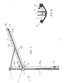
- the laundry rack 1 in the example has four arms 3 arranged at a uniform distance from one another about a vertically standing mast 2, which together serve as a carrier for a laundry rope 7 serve, the sections 7 ⁇ extend from support arm 3 to support arm 3 when they are in their spread apart position (use setting of the laundry rack), as shown in FIGS. 1 and 3.
- the connection of the arms 3 to the mast 2 takes place on the one hand via a support ring 4 which is arranged displaceably along the mast 2.
- the support ring 4 has radially projecting webs 5, to which the respective lower end of the arms 3 is pivotally attached.
- a strut 8 assigned to each arm 3 is provided, which is articulated to one end at a distance from the lower end of the arms 3.
- the other end, ie the end of the struts 8 facing away from the arm 3, is likewise pivotably mounted on a head part 10 of the mast 2.
- the support arms 3 are provided with laterally projecting wings which are either rigidly or pivotably attached to the arms 3, preferably in the region of their front edge.
- FIG. 4 An embodiment of such a construction is shown as a cross section in a horizontal plane through the closed laundry rack in FIG. 4.
- the mast 2 is formed by a generally cylindrical aluminum hollow profile, which, however, has four longitudinally extending depressions 9 arranged uniformly distributed along its circumference. These take up, in the folded state of the laundry rack, the support arms 3, the latter being formed by box profiles. Such an arrangement results in a pronounced stability in comparison small cross-sectional dimensions.
- the box profiles have a cavity 11 open towards the mast 2, in which the struts 8 dip.
- the part of the box sections facing away from the mast 2, which forms the arms 3, is provided with bores 12 for receiving the laundry rope 7.
- the outer, closed end of the box profiles is provided with two wing elements 6a, which are attached in the region of the outer edge of the arm 3 and protrude therefrom.
- These wing elements 6a can be part of the box profile, i.e. be integrally formed on this. They extend slightly inclined from the side surface 3a, at a slightly acute angle, towards the outside, the width of which is dimensioned such that its free edge 6 ⁇ comes to lie in the immediate vicinity of the free edge 6 ⁇ of the adjacent wing element 6a or even touches it .
- the laundry rack when the laundry rack is folded, four cavities 14 are created, which are delimited by two adjacent wing elements 6a, two adjacent outer surfaces 3a of the arms 3 and an area 2a of the outer surface of the mast 2.
- the hanging laundry rope sections 7a of the laundry rope 7 are accommodated in these four cavities 14.
- the length of the wing elements 6a is dimensioned such that the total length of the hanging cable sections is covered or "packed” with certainty; ie the wing elements 6a extend at least least from the bore 12 of the arms 3 provided for the outermost rope section 7a to the deflection point of the innermost rope section 7a. The exact length is to be determined in individual cases.
- guide elements are provided which are displaceably mounted along the arms and which, during the retraction of the arms 3, i. during the movement of the arms 3 from the spread-out operating position into the closed rest position resting against the mast 2, the loosely hanging laundry rope sections 7 'into the cavities 14.
- the guide element In the exemplary embodiment shown in FIG. 5, the guide element, generally designated 15, has the shape of an elongated guide body 16 which extends in the longitudinal direction of the arm 3 in question and can be freely displaced along the same.
- the laundry rack 1 has five arm-to-arm extensions Rope sections 7 ⁇ , which are each attached to the arm 3 at the ends.
- the length of the guide body 16 is chosen so that its longitudinal dimension corresponds approximately to the distance between the top and bottom rope section 7 ⁇ .
- the guide body 16 is provided with a first driver 17 which permanently overlaps the uppermost rope section 7 ⁇ and with further drivers 18 which temporarily overlap the rope sections below.
- first driver 17 which permanently overlaps the uppermost rope section 7 ⁇
- further drivers 18 which temporarily overlap the rope sections below.
- the shorter and shorter rope sections 7 ⁇ from top to bottom, which adjoin the uppermost rope section 7 ⁇ , are temporarily gripped by the catches 18, directed in the downward direction and towards the mast 2 and then released by the currently effective catch, in order to swivel in as they progress of the arm 3 and thus progressive displacement of the guide body 16 to be detected and guided by the subsequent driver 18.
- the guide body 16 can also be pushed down manually if this should be necessary, for example with a slightly jammed guide body or when using ropes that should be extremely stiff (eg due to very low temperature) , so that the dead weight of the guide body 16 is no longer sufficient for a perfect introduction of the cable sections 7 'into the cavities 14.
- each of the guide bodies 16 is equipped with two drivers 17 and with drivers 18 arranged in pairs, specifically in such a way that the two drivers 17 overlap the uppermost cable sections 7 'emanating from the associated arm 3 and the further drivers 18 arranged in pairs with the pairs below each of rope sections 7 ⁇ cooperate.
- the laundry rack 1 comprises a weight 19 arranged in the interior of its mast 2, which is connected to the lower end of the guide element 15 via a cable pull.
- the cable extends with a first section 20a from the weight 19 to a first deflection roller 21 at the head end of the mast 2, with a second section 20b from the first deflection roller 21 to a second deflection roller 22, and with a third section 20c from the second deflection roller 22 to the guide element 15.
- the cable comprises a first section 23a which extends from a lower anchoring point X, e.g. on the mast 2, up to a first deflecting roller 24, a second section 23b, which extends from the deflecting roller 24 to one end of the guide element 21, a third section 23c, which extends from the other end of the guide element 21 via one arranged at the end of the arm 3
- Deflection roller 25 leads to a third deflection roller 26, and finally a fourth section 23d from the third deflection roller 26 to an anchoring point Y, for example in the area of the upper end of the mast 2.
- the axes of rotation of the two deflection rollers 24 and 26 are not, as shown in the drawing, outside the arm 3, but rather coincide with the axis Z, i.e. with the pivot axis of the arm 3 on the support ring 4.
- the guide roller 25 is mounted at the end of the support arm 3.
- the guide element 21 is provided with a laterally protruding driver 22, which projects into the region of the cable sections 7 ′ extending from the arm 3.
- the cable sections 7 ⁇ when the guide element 21 is displaced in the direction of arrow P along the arm 3, are placed against the arm 3 and finally reach the cavities 14 mentioned above in an orderly manner.
Landscapes
- Engineering & Computer Science (AREA)
- Textile Engineering (AREA)
- Accessory Of Washing/Drying Machine, Commercial Washing/Drying Machine, Other Washing/Drying Machine (AREA)
- Detail Structures Of Washing Machines And Dryers (AREA)
- Transition And Organic Metals Composition Catalysts For Addition Polymerization (AREA)
Abstract
Description
Die vorliegende Erfindung betrifft ein Wäschegestell mit den im Oberbegriff des Patentanspruches 1 aufgezeigten Merkmalen.The present invention relates to a laundry rack with the features shown in the preamble of
Ein Wäschegestell ähnlicher Art ist z.B. aus der CH-PS 390 863 bekannt und in zahlreichen Ausführungsformen auf dem Markt präsent. Ein solches Wäschegestell kann von einer Gebrauchsstellung, in welcher ein Wäscheseil zwischen im Beipielsfall vier abstehenden Tragarmen gespannt und somit zur Aufnahme der Wäsche bereit ist, in eine zusammengeklappte Ruhestellung gebracht werden, in der die sich zwischen den Tragarmen erstreckenden Wäscheseilabschnitte lose herunterhängen. Nachteilig dabei ist, dass die lose herunterhängenden Wäscheseilabschnitte dazu neigen, sich zu verwirren, dass sie einer Verschmutzung ausgesetzt sind, wenn das gesamte Wäschegestell nicht mit einer Hülle umschlossen wird, und dass ein dermassen zusammengeklapptes Wäschegestell, wenn es am Gebrauchsort stehengelassen wird, insgesamt unästhetisch und infolge der ungeordnet herumhängenden Wäscheseilabschnitte unordentlich wirkt.A laundry rack of a similar type is e.g. known from CH-PS 390 863 and present in numerous embodiments on the market. Such a laundry rack can be brought from a position of use, in which a laundry rope is stretched between four projecting support arms and is thus ready to receive the laundry, into a folded rest position, in which the laundry rope sections extending loosely hang down between the support arms. The disadvantages here are that the loosely hanging laundry rope sections tend to get confused, that they are exposed to contamination if the entire laundry rack is not enclosed by a cover, and that a laundry rack folded to such an extent, when it is left at the place of use, is overall unaesthetic and looks messy due to the messy hanging rope sections.
Um diese Nachteile zu vermeiden, wurde bereits z.B. in der DE-OS 32 00 013 vorgeschlagen, ein solches Wäschegestell derart weiterzubilden, dass dieses mit einer Wäscheleineneinzugsvorrichtung versehen wird, durch die die Wäscheleine beim Zusammenklappen des Wäschegestells automatisch in die Arme des Gestells ein gezogen wird. Theoretisch ist es wohl möglich, das angestrebte Ziel mit einer solchen Einzugsvorrichtung zu erreichen, doch umfasst diese eine Vielzahl von störungsanfälligen, dem Verschleiss unterworfenen Teilen; dies ist aber speziell bei einem Haushaltartikel für den täglichen Bedarf unerwünscht, da ein solcher möglichst während vieler Jahre problemlos funktionieren soll. Dazu kommt der Kostenfaktor: Eine vergleichsweise komplizierte Seileinzugsmechanik erhöht die Herstellungskosten eines Wäschegestells in beträchtlichem Masse, insbesondere wenn auf eine robuste, gegen Fehlbedienung unempfindliche Konstruktion geachtet werden muss.In order to avoid these disadvantages, it has already been proposed, for example in DE-OS 32 00 013, to further develop such a laundry rack in such a way that it is provided with a clothes line pull-in device by means of which the clothes line automatically enters the arms of the rack when the laundry rack is folded up is pulled. Theoretically, it is possible to achieve the desired goal with such a retraction device, but this comprises a large number of parts which are susceptible to malfunction and are subject to wear; however, this is particularly undesirable in the case of a household article for daily use, since it should function without problems for many years. In addition, there is the cost factor: a comparatively complicated rope pull-in mechanism increases the manufacturing costs of a laundry rack to a considerable extent, especially if a robust construction that is insensitive to incorrect operation must be taken into account.
Der Anmelder hat in der EP-PA 85113512.9 deshalb schon vorgeschlagen, das Wäscheseil bei zusammengeklapptem Wäschegestell in dafür vorgesehene Hohlräume gleichsam "einzupacken" und nicht in die Arme des Gestells einzuziehen. Damit kann auf einfachste Weise, ohne Bereitstellung einer aufwendigen, damit teuren und störungsanfälligen Mechanik, sichergestellt werden, dass die lose herabhängenden Wäscheseilabschnitte bei zusammengelegtem Wäschegestell gegen Verschmutzung und Verwirrung geschützt sind, wobei gleichzeitig ein ästhetisch ansprechendes Erscheinungsbild des zusammengelegten Wäschegestells erreicht wird.The applicant has therefore already proposed in EP-PA 85113512.9 to "pack" the laundry rope into the cavities provided for this purpose when the laundry rack is folded up and not to pull it into the arms of the rack. In this way, it can be ensured in the simplest way, without providing a complex, thus expensive and failure-prone mechanism, that the loosely hanging laundry rope sections are protected against dirt and confusion when the laundry rack is folded, while at the same time achieving an aesthetically pleasing appearance of the folded laundry rack.
Ein Problem, das sich aber bei einer Konstruktion gemäss der EP-PA 85113512.9 stellt, besteht darin, während des zusammenklappens des Wäschegestells für ein eindeutiges und sicheres Hineinleiten der lose herabhängenden Seilabschnitte in die zur Aufnahme derselben vorgesehenen Hohlräume zu sorgen.A problem that arises with a construction according to EP-PA 85113512.9 is that during the folding of the laundry rack for a clear and secure Introduce the loosely hanging rope sections into the cavities provided for receiving the same.
Es ist die Aufgabe der Erfindung, hier Abhilfe zu schaffen und eine Lösung vorzuschlagen, die mit einem Minimum an zusätzlicher Mechanik, in einfachster Weise, eine zwangsläufige Führung bzw. Leitung der lose herabhängenden Seilabschnitte in die gewünschte Richtung, d.h. in die Hohlräume hinein bewirkt.It is the object of the invention to remedy this situation and to propose a solution which, with a minimum of additional mechanics, in the simplest way, inevitably guides or guides the loosely hanging rope sections in the desired direction, i.e. into the cavities.
Die Lösung dieser Erfindungsaufgabe erfolgt bei einem gattungsgemässen Wäschegestell aufgrund der Merkmale im Kennzeichen des Patentanspruches 1. Besondere Ausführungsarten und Weiterbildungen des Erfindungsgegenstandes sind in den abhängigen Ansprüchen 2 bis 7 umschrieben.This object of the invention is achieved in a generic laundry rack based on the features in the characterizing part of
Im folgenden werden Ausführungsbeispiele des Erfindungsgegenstandes, unter Bezugnahme auf die beiliegenden Zeichnungen, näher erläutert. In den Zeichnungen zeigen:
- Fig. 1 eine schematische Gesamt-Seitenansicht eines Ausführungsbeispiels eines Wäschegestells gemäss der Erfindung in Gebrauchsstellung, d.h. in aufgespanntem Zustand,
- Fig. 2 eine Gesamtansicht des Ausführungsbeispieles gemäss Fig. 1 von oben,
- Fig. 3 eine schematische Gesamt-Seitenansicht des Wäschegestells gemäss Fig. 1 in Ruhestellung, d.h. in zusammengeklapptem Zustand,
- Fig. 4 einen Querschnitt in einer horizontalen Ebene durch ein Ausführungsbeispiel eines Wäschegestells in zusammengeklapptem Zustand,
- Fig. 5 eine schematische, vergrösserte Teilansicht des aufgespannten Wäschegestells von der Seite, in einer ersten Ausführungsform,
- Fig. 6 eine schematische, vergrösserte Teilansicht des aufgespannten Wäschegestells von der Seite, in einer zweiten Ausführungsform,
- Fig. 7 eine schematische, vergrösserte Teilansicht des aufgespannten Wäschegestells von der Seite, in einer dritten Ausführungsform, und
- Fig. 8 einen vergrösserten Detailquerschnitt durch einen Arm und ein Führungselement.
- 1 is a schematic overall side view of an embodiment of a laundry rack according to the invention in the use position, ie in the open state,
- 2 is an overall view of the embodiment of FIG. 1 from above,
- 3 shows a schematic overall side view of the laundry rack according to FIG. 1 in the rest position, ie in the folded state,
- 4 shows a cross section in a horizontal plane through an exemplary embodiment of a laundry rack in the folded state,
- 5 is a schematic, enlarged partial view of the stretched laundry rack from the side, in a first embodiment,
- 6 is a schematic, enlarged partial view of the stretched laundry rack from the side, in a second embodiment,
- Fig. 7 is a schematic, enlarged partial view of the stretched laundry rack from the side, in a third embodiment, and
- 8 shows an enlarged detail cross section through an arm and a guide element.
Das Wäschegestell 1 besitzt im Beispielsfall vier in gleichmässigem Abstand voneinander um einen vertikal stehenden Mast 2 angeordnete Arme 3, die gemeinsam als Träger für ein Wäscheseil 7 dienen, dessen Abschnitte 7ʹ sich von Tragarm 3 zu Tragarm 3 erstrecken, wenn diese in ihrer auseinandergespreizten Stellung (Gebrauchssetellung des Wäschegestells) sind, wie es in Fig. 1 und 3 dargestellt ist. Die Verbindung der Arme 3 mit dem Mast 2 erfolgt einerseits über einen Tragring 4, der entlang des Mastes 2 verschiebbar angeordnet ist. Der Tragring 4 besitzt radial abstehende Stege 5, an welchen das jeweils untere Ende der Arme 3 schwenkbar befestigt ist. Andererseits ist je eine jedem Arm 3 zugeordnete Strebe 8 vorgesehen, die einerends, im Abstand zum unteren Ende der Arme 3, an diesen gelenkig befestigt ist. Das andere Ende, d.h. das dem Arm 3 abgekehrte Ende der Streben 8, ist an einem Kopfteil 10 des Mastes 2 ebenfalls schwenkbar gelagert.The
Bei Nichtgebrauch des Wäschegestells 1 sind die Arme 3 gegen den Mast 2 geschwenkt und folglich auch die Streben 8; der Tragring 4 befindet sich in seiner untersten Position und die zuvor gespannten Wäscheseilabschnitte 7ʹ hängen lose zwischen den Armen 3 durch.When the
Um eine Verschmutzung und ein Verwirren der lose durchhängendenn Wäscheseilabschnitte zu verhindern, ist vorgesehen, dass bei eingezogener Ruhestellung der Arme 3, zwischen den Armen 3 und dem Mast 2, Hohlräume geschaffen sind, in welchen die sonst lose herabhängenden Wäscheseilabschnitte aufgenommen werden. Dabei bietet es sich an, zur Schaffung dieser Hohlräume die Arme 3 mit beidseitig von deren Vorderkante abstehenden Flügelelementen zu versehen, die in Fig. 1 bis 3 allgemein mit 6 bezeichnet sind. Wie im folgenden noch näher erläutert werden wird, begrenzen diese Flügelelemente 6, zusammen mit den Seitenflächen der Tragarme 3 und mit Bereichen der Oberfläche des Mastes 2, vier Hohlräume 14 zur Aufnahme der herabhängenden Wäscheseilabschnitte, sobald das Wäschesgestell 1 in seiner zusammengeklappten Ruhelage ist. Diese Situation ist in einer schematischen Seiten ansicht in Fig. 2 dargestellt. Man sieht schon aus dieser schematischen Darstellung, dass das Wäschegestell derart einen ordentlichen und ästhetisch befriedigenden Anblick bietet.In order to prevent contamination and confusion of the loosely sagging laundry rope sections, it is provided that, when the
In einer praktischen Ausführung eines solchen Wäschegestells sind die Tragarme 3 mit seitlich abstehenden Flügeln versehen, die entweder starr oder schwenkbar an den Armen 3, vorzugsweise im Bereich deren vorderen Kante befestigt sind.In a practical embodiment of such a laundry rack, the
Ein Ausführungsbeispiel einer solchen Konstruktion ist als Querschnitt in einer Horizontalebene durch das geschlossene Wäschegestell in Fig. 4 dargestellt. Der Mast 2 ist durch ein generell zylindrisches Aluminium-Hohlprofil gebildet, das jedoch vier entlang seines Umfanges gleichmässig verteilt angeordnete, längsverlaufende Vertiefungen 9 aufweist. Diese nehmen, im zusammengeklappten Zustand des Wäschegestells, die Tragarme 3 auf, welch letztere durch Kastenprofile gebildet sind. Eine solche Anordnung ergibt eine ausgeprägte Stabilität bei vergleichsweise geringen Querschnittsabmessungen.An embodiment of such a construction is shown as a cross section in a horizontal plane through the closed laundry rack in FIG. 4. The
Die Kastenprofile besitzen einen gegen den Mast 2 offenen Hohlraum 11, in welchen die Streben 8 eintauchen. Der vom Mast 2 abgewandte Teil der Kastenprofile, das die Arme 3 bildet, ist mit Bohrungen 12 zur Aufnahme des Wäscheseils 7 versehen. Das äussere, geschlossene Ende der Kastenprofile ist, wie in Fig. 4 gezeigt, mit je zwei im Bereich der äusseren Kante des Armes 3 angebrachten, von diesem abstehenden Flügelelementen 6a versehen. Diese Flügelelemente 6a können Teil des Kastenprofils, d.h. einstückig an diesem angeformt sein. Sie erstrecken sich von der Seitenfläche 3a etwas geneigt, unter einem leicht spitzen Winkel, gegen aussen, wobei deren Breite so bemessen ist, dass deren freie Kante 6ʹ in unmittelbare Nähe der freien Kante 6ʹ des benachbarten Flügelelementes 6a zu liegen kommt bzw. diese sogar berührt.The box profiles have a cavity 11 open towards the
Damit sind, bei zusammengeklapptem Wäschegestell, vier Hohlräume 14 geschaffen, die durch zwei benachbarte Flügelelemente 6a, zwei benachbarte Aussenflächen 3a der Arme 3 und einen Bereich 2a der Aussenfläche des Mastes 2 begrenzt sind. In diesen vier Hohlräumen 14 finden die herabhängenden Wäscheseilabschnitte 7a des Wäscheseils 7 Aufnahme. Die Länge der Flügelemente 6a ist dabei so bemessen, dass mit Sicherheit die Gesamt-Längenausdehnung der herabhängenden Seilabschnitte abgedeckt bzw. "verpackt" ist; d.h. die Flügelelemente 6a erstrecken sich minde stens von der für den äussersten Seilabschnitt 7a vorgesehenen Bohrung 12 der Arme 3 bis zum Umlenkpunkt des innersten Seilabschnittes 7a. Die exakte Länge ist im Einzelfall festzulegen.Thus, when the laundry rack is folded, four
Um nun während des Zusammenklappens des Wäschegestells, d.h. beim Entspannen des Wäscheseils 7, dafür zu sorgen, dass die lose herabhängenden Seilabschnitte 7ʹ in die für deren Aufnahem vorgesehenen Hohlräume 14 gelangen, sind gemäss der Erfindung entlang der Arme verschiebbar gelagerte Führungselemente vorgesehen, die während des Einziehens der Arme 3, d.h. während der Bewegung der Arme 3 von der ausgespreizten Betriebsstellung in die am Mast 2 anliegende, beigeklappte Ruhestellung, die lose herabhängenden Wäscheseilabschnitte 7ʹ in die Hohlräume 14 hineinleiten.Now, during the folding of the laundry rack, i.e. when the
Beim in Fig. 5 dargestellten Ausführungsbeispiel besitzt das generell mit 15 bezeichnete Führungselement die Gestalt eines länglichen, sich in Längsrichtung des betreffenden Armes 3 erstreckenden und entlang desselben frei verschiebbaren Füh-rungskörpers 16. Im Beispielsfall besitzt das Wäschegestell 1 fünf sich von Arm zu Arm erstreckende Seilabschnitte 7ʹ, die endseitig jeweils am Arm 3 befestigt sind. Die Länge des FühFührungskörpers 16 ist dabei so gewählt, dass seine Längsabmessung etwa der Distanz zwischen oberstem und unterstem Seilabschnitt 7ʹ entspricht.In the exemplary embodiment shown in FIG. 5, the guide element, generally designated 15, has the shape of an
Der Führungskörper 16 ist mit einem ersten, den obersten Seilabschnitt 7ʹ permanent übergreifenden Mitnehmer 17 und mit weiteren, die gegen unten nachfolgenden Seilabschnitte vorübergehend übergreifenden Mitnehmern 18 versehen. Beim Zusammenklappen der Arme 3, wobei die Wäscheseilabschnitte 7ʹ entspannt werden und die Tendenz haben, nach unten durchzuhängen, gleitet der Führungskörper unter der Wirkung der Schwerkraft entlang des Armes 3 gegen unten. Dabei geschieht folgendes: Der oberste, längste Wäscheseilabschnitt 7ʹ wird permanent vom Mitnehmer 17 übergriffen und dadurch mit fortschreitender Entspannung dieses Seilabschnittes 7ʹ nach unten gezogen, und zwar zunehmend zum Mast 2 hin, je mehr der Arm 3 eingeschwenkt wird. Die von oben gegen unten immer kürzeren Seilabschnitte 7ʹ, die sich an den obersten Seilabschnitt 7ʹ anschliessen, werden von den Mitnehmern 18 vorübergehend erfasst, in Richtung gegen unten und zum Mast 2 hin geleitet und dann vom momentan wirksamen Mitnehmer wieder losgelassen, um bei fortschreitendem Einschwenken des Armes 3 und damit fortschreitender Verschiebung des Führungskörpers 16 vom nachfolgenden Mitnehmer 18 erfasst und geleitet zu werden.The
Damit ist erreicht, dass alle lose herabhängenden Seilabschnitte 7ʹ zuverlässig und eindeutig zum Mast 2 hin und damit in die Hohlräume 14 hinein geleitet werden, um dort gegen Verschmutzung geschützt aufgenommen zu werden. Bei zusammengeklapptem Wäschegestell 1, wie es in Fig. 3 dargestellt ist, befindet sich der Führungskörper 16 in einer unteren Endstellung. Beim neuerlichen Aufspreizen der Arme 3, wenn das Wäschegestell 1 wieder in Betrieb genommen wird, wird der Führungskörper 16 durch den Mitnehmer 17, der immer noch den obersten Seilabschnitt 7ʹ übergreift, wieder entlang des Armes 3 hinaufgezogen, bis alle Seilabschnitte 7ʹ gespannt sind. Bei dieser Bewegung der Arme 3 üben die Mitnehmer 18 keine Funktion aus.This ensures that all loosely hanging rope sections 7ab are reliably and unambiguously directed towards the
Es versteht sich, dass während des Zusammenklappens des Wäschegestells 1 der Führungskörper 16 zudem manuell heruntergeschoben werden kann, falls dies erforderlich sein sollte, zum Beispiel bei etwas klemmendem Führungskörper oder bei Verwendung von Seilen, die (z.B. infolge sehr tiefer Temperatur) ausgesprochen steif sein sollten, sodass das Eigengewicht des Führungskörpers 16 für eine einwandfreie Hineinleitung der Seilabschnitte 7ʹ in die Hohlräume 14 nicht mehr ausreicht.It goes without saying that during the folding of the
Bei einem bevorzugten Ausführungsbeispiel im Falle eines Wäscheständers 1 mit vier Armen 3, wie er in der Fig. 1 und 2 dargestellt ist, sind nur zwei einander gegenüberliegende Arme 3 mit Führungskörpern 16 versehen. Dafür ist jeder der Führungskörper 16 mit je zwei Mitnehmern 17 und mit paarweise angeordneten Mitnehmern 18 ausgerüstet, und zwar derart, dass die beiden Mitnehmer 17 die jeweils vom zugeordneten Arm 3 ausgehenden, obersten Seilabschnitte 7ʹ übergreifen und die paarweise angeordneten, weiteren Mitnehmer 18 mit den jeweils darunter liegenden Paaren von Seilabschnitten 7ʹ zusammenwirken.In a preferred embodiment in the case of a
Beim Ausführungsbeispiel gemäss Fig. 6 ist eine zwangsläufig unterstützte Abwärtsbewegung des Führungselementes 15 entlang des Armes 3 vorgesehen. Zu diesem Zweck umfasst das Wäschegestell 1 ein im Inneren seines Mastes 2 angeordnetes Gewicht 19, das über einen Seilzug mit dem unteren Ende des Führungselementes 15 verbunden ist. Der Seilzug erstreckt sich mit einem ersten Abschnitt 20a vom Gewicht 19 zu einer ersten Umlenkrolle 21 am Kopfende des Mastes 2, mit einem zweiten Abschnitt 20 b von der ersten Umlenkrolle 21 zu einer zweiten Umlenkrolle 22, und mit einem dritten Abschnitt 20c von der zweiten Umlenkrolle 22 zum Führungselement 15. Damit ist gewährleistet, dass das Führungselement 15 sicher und zuverlässig entlang des Armes 3 heruntergezogen wird, auch wenn dieses etwas klemmen sollte, und weiter, dass auch etwas steife Wäscheseile mit sanftem Nachdruck in die Hohlräume 14 hineingeleitet werden. Beim Aufspannen des Wäschegestells wird das Führungselement 15 dank des Eingriffs des Mitnehmers 17 am bzw. an den obersten Seilabschnitt(en) 7ʹ wieder entlang des Armes 3 nach oben gezogen; damit gelangt das Gewicht 19 ebenfalls wieder in seine obere Ausgangslage.In the exemplary embodiment according to FIG. 6, an inevitably supported downward movement of the
In den Fig. 7 und 8 ist eine weitere Ausführungsform des Wäschegestells 1 dargestellt. Hier ist eine doppelseitig wirkende, zwangsläufige Bewegung des nun mit 21 bezeichneten Führungselementes vorgesehen. Wiederum ist ein Seilzug vorgesehen, der der Uebersichtlichkeit halber schematisch etwas im Abstand von den Teilen des Wäschegestells 1 gezeichnet ist.7 and 8, a further embodiment of the
Der Seilzug umfasst einen ersten Abschnitt 23a, der sich von einem unteren Verankerungspunkt X, z.B. am Mast 2, bis zu einer ersten Umlenkrolle 24 erstreckt, einen zweiten Abschnitt 23b, der von der Umlenkrolle 24 zum einen Ende des Führungselementes 21 verläuft, einen dritten Abschnitt 23c, der vom anderen Ende des Führungselementes 21 über eine am Ende des Armes 3 angeordnete Umlenkrolle 25 zu einer dritten Umlenkrolle 26 führt, und schliesslich einen vierten Abschnitt 23d von der dritten Umlenkrolle 26 zu einem Verankerungspunkt Y, z.B. im Bereich des oberen Ende des Mastes 2. Es versteht sich, dass die Drehachsen der beiden Umlenkrollen 24 und 26 nicht, wie zeichnerisch dargestellt, ausserhalb des Armes 3 liegen, sondern mit der Achse Z zusammenfallen, d.h. mit der Schwenkachse des Armes 3 am Tragring 4. In entsprechender Weise ist die Umlenkrolle 25 am Ende des Tragarmes 3 gelagert.The cable comprises a first section 23a which extends from a lower anchoring point X, e.g. on the
Gemäss der Darstellung in Fig. 8 ist das Führungselement 21 mit einem seitlich abstehenden Mitnehmer 22 versehen, der in den Bereich der sich vom Arm 3 wegerstreckenden Seilabschnitte 7ʹ ragt. Dadurch werden die Seilabschnitte 7ʹ, bei einer Verschiebung des Führungselementes 21 in Richtung des Pfeiles P entlang des Armes 3, an letzteren angelegt und gelangen schliesslich geordnet in die zuvor erwähnten Hohlräume 14.According to the illustration in FIG. 8, the
Bei einem Zusammenklappen des Wäschegestells 1 gemäss Fig. 7 geschieht folgendes:
Durch die gewählte Kinematik und aufgrund der Tatsache, dass die Gesamtlänge des Seilzugs konstant ist, verkürzen sich die Abschnitte 23a und 23b, während sich die Abschnitte 23c und 23c im selben Mass verlängern. Die Folge davon ist, dass das Führungselement 21 in Richtung des Pfeiles P entlang des Armes 3 verschoben wird. Beim Auseinanderspreizen des Wäschegestells 1 erfolgt der Umgekehrte Vorgang. Es ist somit eine zweiseitig wirkende, zwangsläufige Verschiebung des Führungsorganes 21 gegeben. Um Toleranzen bzw. eine eventuell auftretende Dehnung des für den Seilzug verwendeten Seils zu kompensieren, kann z.B. im Bereich des Verankerungspunktes X eine Feder 27 eingefügt sein.When the
Due to the chosen kinematics and due to the fact that the total length of the cable is constant, the
Claims (7)
Priority Applications (4)
| Application Number | Priority Date | Filing Date | Title |
|---|---|---|---|
| DE8686100149T DE3666056D1 (en) | 1986-01-08 | 1986-01-08 | Laundry dryer framework |
| AT86100149T ATE46929T1 (en) | 1986-01-08 | 1986-01-08 | LAUNDRY RAIL. |
| EP86100149A EP0228494B1 (en) | 1986-01-08 | 1986-01-08 | Laundry dryer framework |
| US06/940,629 US4735326A (en) | 1986-01-08 | 1986-12-11 | Clothes drying apparatus |
Applications Claiming Priority (1)
| Application Number | Priority Date | Filing Date | Title |
|---|---|---|---|
| EP86100149A EP0228494B1 (en) | 1986-01-08 | 1986-01-08 | Laundry dryer framework |
Publications (2)
| Publication Number | Publication Date |
|---|---|
| EP0228494A1 true EP0228494A1 (en) | 1987-07-15 |
| EP0228494B1 EP0228494B1 (en) | 1989-10-04 |
Family
ID=8194815
Family Applications (1)
| Application Number | Title | Priority Date | Filing Date |
|---|---|---|---|
| EP86100149A Expired EP0228494B1 (en) | 1986-01-08 | 1986-01-08 | Laundry dryer framework |
Country Status (3)
| Country | Link |
|---|---|
| EP (1) | EP0228494B1 (en) |
| AT (1) | ATE46929T1 (en) |
| DE (1) | DE3666056D1 (en) |
Cited By (6)
| Publication number | Priority date | Publication date | Assignee | Title |
|---|---|---|---|---|
| EP0357803A1 (en) * | 1988-07-29 | 1990-03-14 | LEIFHEIT Aktiengesellschaft | Device for protecting the lines of a rotary clothes dryer |
| EP0514561A1 (en) * | 1991-05-18 | 1992-11-25 | LEIFHEIT Aktiengesellschaft | Framework for airing and drying |
| EP0882833A1 (en) * | 1997-06-05 | 1998-12-09 | LEIFHEIT Aktiengesellschaft | Framework for airing and drying |
| EP1245715A2 (en) * | 2001-03-30 | 2002-10-02 | Blome-Tillmann, Gerhard | Clothes drying rack |
| EP1760188A1 (en) * | 2005-09-02 | 2007-03-07 | Stewi AG | Collapsible clothes drying rack |
| EP2642015A1 (en) * | 2012-03-19 | 2013-09-25 | Stewi AG | Folding clotheshorse |
Families Citing this family (3)
| Publication number | Priority date | Publication date | Assignee | Title |
|---|---|---|---|---|
| DE10345874B3 (en) * | 2003-09-30 | 2005-01-05 | Leifheit Ag | Laundry drying frame, with carrier arms for the laundry lines on an upright pole, has guides at the arms to lead the line loops into the spaces between the carrier arms when folded together |
| DE102004060508B3 (en) * | 2004-12-16 | 2006-03-30 | Leifheit Ag | Drying unit for washing, comprises a pole with carrier arms attached to a sliding linkage, spreading arms, guide elements and a washing line |
| DE102006014107A1 (en) | 2006-03-24 | 2007-09-27 | Leifheit Ag | Cloth feeding component for e.g. rotary cloth drier, has receiving area e.g. slot and/or recess, for temporarily receiving part of washed clothes, where feeding component is designed as scroller and comprises wheels arranged at base |
Citations (6)
| Publication number | Priority date | Publication date | Assignee | Title |
|---|---|---|---|---|
| CH390863A (en) * | 1957-03-19 | 1965-04-30 | Goelz Brugger Alice Maria | Laundry hanging device that can be operated like an umbrella |
| EP0002599A1 (en) * | 1977-12-12 | 1979-06-27 | William Gordon Hildreth | Improvements in and relating to clotheslines |
| GB2055572A (en) * | 1979-06-14 | 1981-03-11 | Lin Ching Chang | Adjustable support assembly |
| EP0072930A1 (en) * | 1981-08-21 | 1983-03-02 | LEIFHEIT Aktiengesellschaft | Device for open-air drying and airing of clothes |
| DE3200013A1 (en) * | 1982-01-02 | 1983-08-11 | Leifheit International Günter Leifheit GmbH, 5408 Nassau | VENTILATION AND DRYING RACK WITH DRESSING LINE |
| EP0113788A1 (en) * | 1983-01-13 | 1984-07-25 | LEIFHEIT Aktiengesellschaft | Framework for airing and drying |
-
1986
- 1986-01-08 AT AT86100149T patent/ATE46929T1/en not_active IP Right Cessation
- 1986-01-08 EP EP86100149A patent/EP0228494B1/en not_active Expired
- 1986-01-08 DE DE8686100149T patent/DE3666056D1/en not_active Expired
Patent Citations (6)
| Publication number | Priority date | Publication date | Assignee | Title |
|---|---|---|---|---|
| CH390863A (en) * | 1957-03-19 | 1965-04-30 | Goelz Brugger Alice Maria | Laundry hanging device that can be operated like an umbrella |
| EP0002599A1 (en) * | 1977-12-12 | 1979-06-27 | William Gordon Hildreth | Improvements in and relating to clotheslines |
| GB2055572A (en) * | 1979-06-14 | 1981-03-11 | Lin Ching Chang | Adjustable support assembly |
| EP0072930A1 (en) * | 1981-08-21 | 1983-03-02 | LEIFHEIT Aktiengesellschaft | Device for open-air drying and airing of clothes |
| DE3200013A1 (en) * | 1982-01-02 | 1983-08-11 | Leifheit International Günter Leifheit GmbH, 5408 Nassau | VENTILATION AND DRYING RACK WITH DRESSING LINE |
| EP0113788A1 (en) * | 1983-01-13 | 1984-07-25 | LEIFHEIT Aktiengesellschaft | Framework for airing and drying |
Cited By (7)
| Publication number | Priority date | Publication date | Assignee | Title |
|---|---|---|---|---|
| EP0357803A1 (en) * | 1988-07-29 | 1990-03-14 | LEIFHEIT Aktiengesellschaft | Device for protecting the lines of a rotary clothes dryer |
| EP0514561A1 (en) * | 1991-05-18 | 1992-11-25 | LEIFHEIT Aktiengesellschaft | Framework for airing and drying |
| EP0882833A1 (en) * | 1997-06-05 | 1998-12-09 | LEIFHEIT Aktiengesellschaft | Framework for airing and drying |
| EP1245715A2 (en) * | 2001-03-30 | 2002-10-02 | Blome-Tillmann, Gerhard | Clothes drying rack |
| EP1245715A3 (en) * | 2001-03-30 | 2003-01-08 | Blome-Tillmann, Gerhard | Clothes drying rack |
| EP1760188A1 (en) * | 2005-09-02 | 2007-03-07 | Stewi AG | Collapsible clothes drying rack |
| EP2642015A1 (en) * | 2012-03-19 | 2013-09-25 | Stewi AG | Folding clotheshorse |
Also Published As
| Publication number | Publication date |
|---|---|
| DE3666056D1 (en) | 1989-11-09 |
| ATE46929T1 (en) | 1989-10-15 |
| EP0228494B1 (en) | 1989-10-04 |
Similar Documents
| Publication | Publication Date | Title |
|---|---|---|
| EP0219571B1 (en) | Laundry dryer framework | |
| EP0305623A1 (en) | Pull-out laundry dryer | |
| EP0228494B1 (en) | Laundry dryer framework | |
| DE3200013A1 (en) | VENTILATION AND DRYING RACK WITH DRESSING LINE | |
| DE202014100745U1 (en) | Two-chamber container with bottom flaps and trusses | |
| DE19906395A1 (en) | Display counter has hinged window which moves down to form lid for display surface and is attached to extension arm which fits within cavity in main support arm when window is in closed position, but is horizontal when it is raised | |
| DE2935876C2 (en) | ||
| EP0317737A2 (en) | Fitting for a corner cupboard, in particular a kitchen corner cupboard | |
| EP0229201B1 (en) | Laundry dryer framework | |
| DE2652183B2 (en) | Folding wall suspended from a room ceiling so that it can be moved | |
| DE4323993C3 (en) | Foldable or gatherable curtain | |
| DE69401704T2 (en) | TWO-TRACK TZAG AND SLIDE DEVICE FOR CURTAINS | |
| DE3249358C2 (en) | Ventilation and drying rack with a clothes line | |
| DE19621956B4 (en) | Awning with inevitably moved valance | |
| EP3064385B1 (en) | Vehicle structure with a sliding tarpaulin | |
| EP0213280B1 (en) | Extensible laundry dryer | |
| EP0276627A1 (en) | Laundry support | |
| DE19637341B4 (en) | Ventilation and drying rack | |
| DE4229503C2 (en) | Truck box body with side wall opening mechanism | |
| DE19632973A1 (en) | Shielding or protection device for wall openings | |
| DE2602664A1 (en) | Foldable clothes dryer for fixing to a wall - comprises pivotable arms and sliding hanging-up rods | |
| DE2204217C3 (en) | Garden umbrella | |
| DE8101865U1 (en) | FOOD GRID FOR VILLAGE STATIONS | |
| DE2653123A1 (en) | Slatted blind for irregularly shaped windows - has unequal length slats pivotally mounted in brackets, and tilted by cord passing over top pulley | |
| DE2912514A1 (en) | Folding door or partition section strip groups - are moved by swivelling activating arms engaged by cross-folding arms |
Legal Events
| Date | Code | Title | Description |
|---|---|---|---|
| PUAI | Public reference made under article 153(3) epc to a published international application that has entered the european phase |
Free format text: ORIGINAL CODE: 0009012 |
|
| AK | Designated contracting states |
Kind code of ref document: A1 Designated state(s): AT BE CH DE FR GB IT LI LU NL SE |
|
| 17P | Request for examination filed |
Effective date: 19870903 |
|
| 17Q | First examination report despatched |
Effective date: 19880822 |
|
| ITTA | It: last paid annual fee | ||
| GRAA | (expected) grant |
Free format text: ORIGINAL CODE: 0009210 |
|
| AK | Designated contracting states |
Kind code of ref document: B1 Designated state(s): AT BE CH DE FR GB IT LI LU NL SE |
|
| REF | Corresponds to: |
Ref document number: 46929 Country of ref document: AT Date of ref document: 19891015 Kind code of ref document: T |
|
| REF | Corresponds to: |
Ref document number: 3666056 Country of ref document: DE Date of ref document: 19891109 |
|
| ET | Fr: translation filed | ||
| PGFP | Annual fee paid to national office [announced via postgrant information from national office to epo] |
Ref country code: AT Payment date: 19891211 Year of fee payment: 5 |
|
| PGFP | Annual fee paid to national office [announced via postgrant information from national office to epo] |
Ref country code: FR Payment date: 19891212 Year of fee payment: 5 |
|
| PGFP | Annual fee paid to national office [announced via postgrant information from national office to epo] |
Ref country code: SE Payment date: 19891215 Year of fee payment: 5 |
|
| PGFP | Annual fee paid to national office [announced via postgrant information from national office to epo] |
Ref country code: CH Payment date: 19891219 Year of fee payment: 5 |
|
| GBT | Gb: translation of ep patent filed (gb section 77(6)(a)/1977) | ||
| PGFP | Annual fee paid to national office [announced via postgrant information from national office to epo] |
Ref country code: BE Payment date: 19891220 Year of fee payment: 5 |
|
| PGFP | Annual fee paid to national office [announced via postgrant information from national office to epo] |
Ref country code: GB Payment date: 19891231 Year of fee payment: 5 |
|
| PGFP | Annual fee paid to national office [announced via postgrant information from national office to epo] |
Ref country code: DE Payment date: 19900102 Year of fee payment: 5 |
|
| ITF | It: translation for a ep patent filed | ||
| PGFP | Annual fee paid to national office [announced via postgrant information from national office to epo] |
Ref country code: LU Payment date: 19900109 Year of fee payment: 5 |
|
| PG25 | Lapsed in a contracting state [announced via postgrant information from national office to epo] |
Ref country code: LU Free format text: LAPSE BECAUSE OF NON-PAYMENT OF DUE FEES Effective date: 19900131 |
|
| PGFP | Annual fee paid to national office [announced via postgrant information from national office to epo] |
Ref country code: NL Payment date: 19900131 Year of fee payment: 5 |
|
| PLBE | No opposition filed within time limit |
Free format text: ORIGINAL CODE: 0009261 |
|
| STAA | Information on the status of an ep patent application or granted ep patent |
Free format text: STATUS: NO OPPOSITION FILED WITHIN TIME LIMIT |
|
| 26N | No opposition filed | ||
| PG25 | Lapsed in a contracting state [announced via postgrant information from national office to epo] |
Ref country code: GB Effective date: 19910108 Ref country code: AT Effective date: 19910108 |
|
| PG25 | Lapsed in a contracting state [announced via postgrant information from national office to epo] |
Ref country code: SE Effective date: 19910109 |
|
| PG25 | Lapsed in a contracting state [announced via postgrant information from national office to epo] |
Ref country code: LI Effective date: 19910131 Ref country code: CH Effective date: 19910131 Ref country code: BE Effective date: 19910131 |
|
| PG25 | Lapsed in a contracting state [announced via postgrant information from national office to epo] |
Ref country code: NL Effective date: 19910801 |
|
| GBPC | Gb: european patent ceased through non-payment of renewal fee | ||
| NLV4 | Nl: lapsed or anulled due to non-payment of the annual fee | ||
| PG25 | Lapsed in a contracting state [announced via postgrant information from national office to epo] |
Ref country code: FR Effective date: 19910930 |
|
| REG | Reference to a national code |
Ref country code: CH Ref legal event code: PL |
|
| PG25 | Lapsed in a contracting state [announced via postgrant information from national office to epo] |
Ref country code: DE Effective date: 19911001 |
|
| REG | Reference to a national code |
Ref country code: FR Ref legal event code: ST |
|
| EUG | Se: european patent has lapsed |
Ref document number: 86100149.3 Effective date: 19910910 |
|
| PG25 | Lapsed in a contracting state [announced via postgrant information from national office to epo] |
Ref country code: IT Free format text: LAPSE BECAUSE OF NON-PAYMENT OF DUE FEES Effective date: 20050108 |