EP0002599A1 - Improvements in and relating to clotheslines - Google Patents
Improvements in and relating to clotheslines Download PDFInfo
- Publication number
- EP0002599A1 EP0002599A1 EP78300789A EP78300789A EP0002599A1 EP 0002599 A1 EP0002599 A1 EP 0002599A1 EP 78300789 A EP78300789 A EP 78300789A EP 78300789 A EP78300789 A EP 78300789A EP 0002599 A1 EP0002599 A1 EP 0002599A1
- Authority
- EP
- European Patent Office
- Prior art keywords
- stem element
- casing
- stem
- clothesline
- arms
- Prior art date
- Legal status (The legal status is an assumption and is not a legal conclusion. Google has not performed a legal analysis and makes no representation as to the accuracy of the status listed.)
- Withdrawn
Links
Images

Classifications
-
- D—TEXTILES; PAPER
- D06—TREATMENT OF TEXTILES OR THE LIKE; LAUNDERING; FLEXIBLE MATERIALS NOT OTHERWISE PROVIDED FOR
- D06F—LAUNDERING, DRYING, IRONING, PRESSING OR FOLDING TEXTILE ARTICLES
- D06F57/00—Supporting means, other than simple clothes-lines, for linen or garments to be dried or aired
- D06F57/02—Supporting means, other than simple clothes-lines, for linen or garments to be dried or aired mounted on pillars, e.g. rotatably
- D06F57/04—Supporting means, other than simple clothes-lines, for linen or garments to be dried or aired mounted on pillars, e.g. rotatably and having radial arms, e.g. collapsible
Definitions
- the present invention relates to collapsible clotheslines and has particular reference to a clothesline of the kind having divergent arms extending from a centre support and lines extending between the arms.
- collapsible clotheslines are designed to be removed from the use location when not required or else to be stored above ground at this location in a collapsed or otherwise partially disassembled state.
- the removal of a clothesline from its use location naturally involves a measure of inconvenience, which frequently results in the clothesline being left in place even when not in use, thus defeating the advantages offered by that type of clothesline, while storage of a collapsed or partially disassembled clothesline above ground has aesthetic disadvantages, particularly if posts or other such supports remain in place.
- collapsing and subsequent re-erection of the clothesline is usually carried out manually, which involves extra time and inconvenience, especially for elderly or hardicapped persons.
- One object of the present invention is therefore the prcJision of a clothesline which can be collapsed and stored in situ in the ground, thereby to conserve space and to conceal the clothesline from view.
- Another object of the invention is to provide a clothesline of the kind referred to which can be erected by hydraulic pressure, for example mains water pressure, and collapsed by relief of such pressure.
- a collapsible clothesline comprising a casing, a telescopic stem telescopically retractible into and extensible from the casing, the stem comprising an outer stem element and inner stem element . which in use is telescopically retractible downwardly into and extensible upwardly from the outer stem element, first sealing means disposed between the casing and outer stem element to hydraulically seal the casing and outer stem element together second sealing means disposed between the .
- outer and inrcr stem elements to hydraulically seal the stem elements together
- a plurality of arms carried by the outer stem element and pivotable between a use position in which ther extend subtantially radially of the stem and a storage position in which they extend alongside the stem, a plurality . of lengths of line interconnecting the arms, and a plurality of support ties so connecting the arms to the inner stem element at its upper end as to cause the arms to pivot from the storage position to the use position on extension of the inner stem element from the outer stem element and to permit .
- the arms to pivot from the use position to the storage position on retraction of the inner stem element into the outer stem element
- the casing being provided with inlet and outlet means for admission and exhaust of liquid under pressure
- the inner and outer stem elements being provided . with means actable on by such liquid under pressure to effect extension of the outer stem element from the casing and the inner stem element from the outer stem element.
- a clothesline according to the invention may be constructed as a self-contained unit which can be stored in a collapsed state in the ground completely out of sight except for the top of the clothesline at ground level.
- liquid under pressure for example water from a mains source
- the outer stem element can be extended from the casing and the inner stem element in turn from the outer stem element, the extension of the inner stem element simultaneously raising the arms to the use position.
- the inner and outer stem elements can be retracted simply by relief of such pressure, that is by exhausting the liquid from the casing, and the actions of admitting liquid to and exhausting the liquid from the casing can be carried out by the use of such simple controls as conventional taps or other stop cocks.
- the stem is rotatable relative to the casing so that the clothesline can be used in the manner of a conventional rotary clothesline.
- the first sealing means expediently comprises a seal fitted on the lower end of the outer stem element and serving as the means actable on by liquid under pressure to effect extension of the outer stem element from the casing.
- the second sealing means may comprise a similar seal fitted , on the lower end of the inner stem element.
- the sealing means and the means actable on by liquid under pressure can, however, be separate components and the sealing means can be arranged in other locations, for example the second sealing means may comprise a seal fitted to the outer element at its . upper end.
- the arms are pivotally mounted on carrier means at the upper end of the outer stem element, the carrier means preferably being detachably mounted on the outer stem element so as to facilitate disassembly for servicing of the . clothesline.
- the ties which preferably comprise flexible connections such as cords, ropes, wires or chains, are for preference connected to the arms intermediate the ends thereof and to a cover member at the upper end of the inner stem element, the cover member serving to cover the upper end of the casing in the collapsed state of the clothesline.
- a collapsible clothesline in accordance with the first aspect of the invention, the casing of the clothesline being located in a substantially vertical bore in the ground or equivalent support base.
- a collapsible clothesline indicated generally at 10, comprising a tubular plastics casing 11 located in a substantially vertical bore in the ground.
- the casing 11 is closed at its lower end by a cap 12 and is open at its upper end, the depth of the bore being such that the open end of the casing is substantially flush with the surface of the ground.
- a concrete surround 13 may be provided around the open end of the casing.
- a telescopic stem indicated generally at 14 is mounted in the casing 11 to be rotatable therein and to be telescopically extensible from and retractible into the casing, the stem consisting of an outer and lower plastics pipe 15 and an inner and upper galvanised iron pipe 16 of somewhat smaller diameter than the pipe 15, the pipe 16 being extensible from and retractible into the pipe 15.
- the length of the pipe 15 is almost as great as that of the casing 11 while the length of the pipe 16 is about half that of the pipe 15.
- the pipe 15 is provided at its lower end with an annular rubber or plastics seal 17 having a peripheral wall which resiliently bears against the inner wall surface of the casing 11 to effect a hydraulic seal between the casing 11 and pipe 15. Between its peripheral wall and the pipe 15, the seal 17 has a generally planar pressure surface 17a against which water under pressure acts to raise the stem 14, as will be subsequently explained.
- the pipe 15 carries a guide 18 equipped with a plurality of wheels 19 running on the inner wall surface of the casing 11. Balls, rollers or other rollable elements may be used in place of the wheels 19.
- the guide 18 together with the seal 17 centres the pipe 15 in the casing 11 and guides the pipe during its extension from and retraction into the casing.
- the range of extension of the pipe 15 from the casing 11 is limited by a stop means in the form of an annular abutment 20 arranged at the upper end of the casing to be contacted by and to arrest upward movement of the wheels 19 of the guide 18.
- a carrier member 21 Detachably mounted on the upper end of the pipe 15 is a carrier member 21 provided with four guide channels in which are pivotally mounted four equidistantly spaced metal arms 22, the carrier member 21 being supported on the pipe 15 by means of a collar 23 secured to the pipe.
- the carrier member 21 is structured so that the arms are pivotable between a storage positior in which they extend alongside and thus generally parallel to the pipe 15, as shown in . Figure 1, and a use position in which they extend generally radially of the pipe 15, as shown in Figure 2.
- the carrier member 21 includes a peripieral flange portion 24 at its upper end serving as a stop means to limit pivotal movement of the arms beyond the dessribed use position.
- the arms 22 are interconnected by lengths of line 25 (shown in Figure 2 only) wiich act as supports for laundry or other articles to be aired on the clothesline.
- line 25 shown in Figure 2 only
- two or more parallel lengths of such line extend between each pair of adjacent arms.
- the pipe 16 is similarly provided at its lower end with a rubber or plastics seal 26 which is plugged into the end of the pipe 16 and which has a peripheral wall resiliently bearing against the inner wall surface of the pipe 15 to effect a hydraulic seal between the two pipes 15 and 16.
- the seal 26 In the area enclosed by its peripheral wall, the seal 26 has a generally planar pressure surface 26a against which water under pressure acts to extend the pipe 15 out of the pipe 16, as will be described in more detail later.
- a conical metal cover member 27 Mounted on the upper end of the pipe 16 is a conical metal cover member 27, the diameter of which is greater than the external diameter of the casing 11 and which provides a closure for the upper end of the casing 11 in the collapsed state of the clothesline as shown in Figure 1.
- ties 28, for example ropes, cords, wires, chains or other flexible or rigid connections, are each attached at one end to the cover member 27 and at the other end to a respective one of the arms 22 at a point approximately midway along the length of that arm.
- the arrangement is such that with the pipe 15 substantially completely extended from the casing 11, extension of the pipe 16 from the pipe 15 will cause the ties 28 to pivot the arms 22 from the storage position to the use position.
- the upward travel of the pipe 16 is arrested when the arms 22 contact the flange 24 of the carrier member 21.
- the pipe 16 is formed with an opening 29'which is arranged so as to be disposed above the upper end of the pipe 15 when the pipe 16 is fully extended and which serves for the reception of a pin or other locking element bearing on the upper end of the pipe 15 to prevent retraction of the pipe 16.
- the pipe 16 can be locked to the pipe 15 with the arms 22 raised in the use position.
- the clothesline is also equipped with means for gathering in the lengths of line 25 during lowering of the arms 22 to the storage position, and with reference to Figure 2 such means consists of four cords or wires 30 which are each connected to the lengths of line 25 between a respective pair of the arms 22 and at a point midway between the arms, extend over a respective pulley.31 mounted on the carrier member 21, and are attached to a common annular counterweight 32 slidably engaged on the pipe 15.
- the means for gathering in the lengths of line 25 comprises a respective cord or wire connected to the lengths of line 25 between each pair of adjacent arms at a point midway between the arms, and a coil spring connecting the cord or wire, or the innermost one of the lengths of line 25, to the carrier member 21.
- the spring is tensioned when the arms are in the use position and relaxed during movement of the arms to the storage position, so as to draw the lengths of line 25 towards the carrier member 21.
- the casing 11 is provided in its base cap 12 with inlet and outlet means for admission and exhaust of water under pressure, the,inlet and outlet means being provided by respective openings in the cap 12 through which extend, or with which communicate, a pair of water pipes 33 each incorporating a tap or other stop cock (not shown).
- a pair of water pipes 33 each incorporating a tap or other stop cock (not shown).
- One of the water pipes 33 acting as an inlet pipe, is connected to a source of mains water and the other water .
- pipe, acting as an outlet pipe is arranged to discharge into a drain, gutter or other receptacle or simply onto the ground.
- the clothesline 10 In use of the clothesline 10 hereinbefore described, the clothesline is located in position by insertion of the casing 11 into a suitable bore drilled or dug in the ground at a chosen site, the water pipes 33 are laid in, and the concrete surround 13 is poured or placed around the upper end of the casing 11.
- the tap or stop cock in the inlet water pipe is opened to allow water under pressure to flow into the casing 11 and the interior of the pipe 15 below the seal 26.
- the water pressure acts on the pressure surfaces 17a and 26a of the seals 17 and 26 to initially extend the pipe 15 out of the casing 11 and then with the arms 22 clear of the casing, to extend the pipe 16 out of the pipe 15.
- the ties 28 act to pull the arms 22 up from the storage position of Figure 1 to the use position of Figure 2, the counterweight 32 being drawn up the pipe 15 and acting to tension the lengths of line 25.
- the clothesline is now ready for use in the conventional manner and clothes or other items of laundry can be suspended from the lengths of line 25, the stem 14 being rotatable in the casing 11 so that the clothesline functions as rotary clothesline.
- the tap or stop cock in the outlet water pipe is opened to allow the water to escape from the casing 11 and the interior of the pipe 15, which thus relieves the pressure applied to the pressure surfaces 17a and 26a of the seals 17 and 26.
- the construction and arrangement of the clothesline 10 is such that initially the pipe 16 is fully retracted into the pipe 15, with the arms lowering to the storage position under their own weight and the weight of the counterweight 32 gathering in the lengths of line 25, and then the pipe 15 together with the pipe 16 and arms 22 is retracted into the casing 11.
- the cover member 27 comes to bear on the concrete surround 13 and thus covers over and conceals the rest of the clothesline.
- the tap or stop cock of the outlet water pipe may now be turned off so that the clothesline is in readiness for re-erection.
- a pin or other fastening element can be inserted in the opening 29 in the pipe 16 to lock the pipes 15 and 16 together with the arms in the use position, and a quantity of water can be bled-off by opening the tap or stop cock of the outlet water pipe.
- This will result in the stem 14 descending in the casing 11 to an extent governed by the amount of water bled-off, thus placing the lengths of line 25 at a lower level to facilitiate the attachment or removal of laundry.
- the stem 14 can of course be raised back to its fully extended position simply by admitting a replacement quantity of water into the casing 11.
- the clothesline hereinbefore described is thus convenient and economical to operate, does not require lengthy or awkward assembly and disassembly by hand, and is always available at the use location, yet concealed from view.
Abstract
A collapsible clothesline (10) intended to be stored in situ in the ground and to be erected by water pressure. The clothesline comprises a casing (11) intended to be located in a bore in the ground and a stem (14) which is retractible into and extensible from the casing. The stem itself consists of an inner and an outer stem element (15, 16) with the former being retractrble downwardly into and extensible upwardly from the latter A number of arms (22) linked by lines for supporting laundry, are pivoted to the outer stem element (15) and are connected by ties (28) to the upper end of the inner stem element (16). When the inner stem element (16) is extended from the outer stem element (15), with the outer stem element (15) already extended from the casing (11), the ties (28) pull the arms (22) up from a storage position, in which they lie alongside the stem (14), to a use position, in which they extend radially from the stem (14). The clothesline is erected by supplying water pressure to the casing interior and collapsed by relieving such pressure.
Description
- The present invention relates to collapsible clotheslines and has particular reference to a clothesline of the kind having divergent arms extending from a centre support and lines extending between the arms.
- Generally, collapsible clotheslines are designed to be removed from the use location when not required or else to be stored above ground at this location in a collapsed or otherwise partially disassembled state. The removal of a clothesline from its use location naturally involves a measure of inconvenience, which frequently results in the clothesline being left in place even when not in use, thus defeating the advantages offered by that type of clothesline, while storage of a collapsed or partially disassembled clothesline above ground has aesthetic disadvantages, particularly if posts or other such supports remain in place. In addition, collapsing and subsequent re-erection of the clothesline is usually carried out manually, which involves extra time and inconvenience, especially for elderly or hardicapped persons.
- One object of the present invention is therefore the prcJision of a clothesline which can be collapsed and stored in situ in the ground, thereby to conserve space and to conceal the clothesline from view.
- Another object of the invention is to provide a clothesline of the kind referred to which can be erected by hydraulic pressure, for example mains water pressure, and collapsed by relief of such pressure.
- Other objects and advantages of the invention will be apparent from the following description.
- In accordance with a first aspect of the present invention there is provided a collapsible clothesline comprising a casing, a telescopic stem telescopically retractible into and extensible from the casing, the stem comprising an outer stem element and inner stem element . which in use is telescopically retractible downwardly into and extensible upwardly from the outer stem element, first sealing means disposed between the casing and outer stem element to hydraulically seal the casing and outer stem element together second sealing means disposed between the . outer and inrcr stem elements to hydraulically seal the stem elements together, a plurality of arms carried by the outer stem element and pivotable between a use position in which ther extend subtantially radially of the stem and a storage position in which they extend alongside the stem, a plurality . of lengths of line interconnecting the arms, and a plurality of support ties so connecting the arms to the inner stem element at its upper end as to cause the arms to pivot from the storage position to the use position on extension of the inner stem element from the outer stem element and to permit . the arms to pivot from the use position to the storage position on retraction of the inner stem element into the outer stem element, the casing being provided with inlet and outlet means for admission and exhaust of liquid under pressure and the inner and outer stem elements being provided . with means actable on by such liquid under pressure to effect extension of the outer stem element from the casing and the inner stem element from the outer stem element.
- A clothesline according to the invention may be constructed as a self-contained unit which can be stored in a collapsed state in the ground completely out of sight except for the top of the clothesline at ground level. By the admission of liquid under pressure, for example water from a mains source, into the casing the outer stem element can be extended from the casing and the inner stem element in turn from the outer stem element, the extension of the inner stem element simultaneously raising the arms to the use position. The inner and outer stem elements can be retracted simply by relief of such pressure, that is by exhausting the liquid from the casing, and the actions of admitting liquid to and exhausting the liquid from the casing can be carried out by the use of such simple controls as conventional taps or other stop cocks.
- For preference the stem is rotatable relative to the casing so that the clothesline can be used in the manner of a conventional rotary clothesline.
- The first sealing means expediently comprises a seal fitted on the lower end of the outer stem element and serving as the means actable on by liquid under pressure to effect extension of the outer stem element from the casing. The second sealing means may comprise a similar seal fitted , on the lower end of the inner stem element. The sealing means and the means actable on by liquid under pressure can, however, be separate components and the sealing means can be arranged in other locations, for example the second sealing means may comprise a seal fitted to the outer element at its . upper end.
- Expediently, the arms are pivotally mounted on carrier means at the upper end of the outer stem element, the carrier means preferably being detachably mounted on the outer stem element so as to facilitate disassembly for servicing of the . clothesline.
- The ties, which preferably comprise flexible connections such as cords, ropes, wires or chains, are for preference connected to the arms intermediate the ends thereof and to a cover member at the upper end of the inner stem element, the cover member serving to cover the upper end of the casing in the collapsed state of the clothesline.
- According to a second aspect of the invention there is provided a collapsible clothesline in accordance with the first aspect of the invention, the casing of the clothesline being located in a substantially vertical bore in the ground or equivalent support base.
- An embodiment of the invention will now be more particularly described by way of example with reference to the accompanying drawings, in which:-
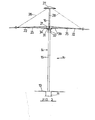
- Figure 1 is a schematic, partly sectioned vertical elevation of a collapsible clothesline according to the said embodiment, the clothesline being in the collapsed state; and
- Figure 2 is a schematic elevation of the clothesline of Figure I in the erected state.
- Referring now to the drawings, there is shown a collapsible clothesline, indicated generally at 10, comprising a
tubular plastics casing 11 located in a substantially vertical bore in the ground. Thecasing 11 is closed at its lower end by acap 12 and is open at its upper end, the depth of the bore being such that the open end of the casing is substantially flush with the surface of the ground. Aconcrete surround 13 may be provided around the open end of the casing. - A telescopic stem indicated generally at 14 is mounted in the
casing 11 to be rotatable therein and to be telescopically extensible from and retractible into the casing, the stem consisting of an outer andlower plastics pipe 15 and an inner and upper galvanisediron pipe 16 of somewhat smaller diameter than thepipe 15, thepipe 16 being extensible from and retractible into thepipe 15. As can be seen in Figure 1, the length of thepipe 15 is almost as great as that of thecasing 11 while the length of thepipe 16 is about half that of thepipe 15. - The
pipe 15 is provided at its lower end with an annular rubber orplastics seal 17 having a peripheral wall which resiliently bears against the inner wall surface of thecasing 11 to effect a hydraulic seal between thecasing 11 andpipe 15. Between its peripheral wall and thepipe 15, theseal 17 has a generallyplanar pressure surface 17a against which water under pressure acts to raise thestem 14, as will be subsequently explained. - A short distance above the
seal 17, thepipe 15 carries aguide 18 equipped with a plurality ofwheels 19 running on the inner wall surface of thecasing 11. Balls, rollers or other rollable elements may be used in place of thewheels 19. Theguide 18 together with theseal 17 centres thepipe 15 in thecasing 11 and guides the pipe during its extension from and retraction into the casing. The range of extension of thepipe 15 from thecasing 11 is limited by a stop means in the form of anannular abutment 20 arranged at the upper end of the casing to be contacted by and to arrest upward movement of thewheels 19 of theguide 18. - Detachably mounted on the upper end of the
pipe 15 is acarrier member 21 provided with four guide channels in which are pivotally mounted four equidistantly spacedmetal arms 22, thecarrier member 21 being supported on thepipe 15 by means of acollar 23 secured to the pipe. Thecarrier member 21 is structured so that the arms are pivotable between a storage positior in which they extend alongside and thus generally parallel to thepipe 15, as shown in . Figure 1, and a use position in which they extend generally radially of thepipe 15, as shown in Figure 2. Thecarrier member 21 includes aperipieral flange portion 24 at its upper end serving as a stop means to limit pivotal movement of the arms beyond the dessribed use position. - The
arms 22 are interconnected by lengths of line 25 (shown in Figure 2 only) wiich act as supports for laundry or other articles to be aired on the clothesline. For preference, two or more parallel lengths of such line extend between each pair of adjacent arms. - The
pipe 16 is similarly provided at its lower end with a rubber orplastics seal 26 which is plugged into the end of thepipe 16 and which has a peripheral wall resiliently bearing against the inner wall surface of thepipe 15 to effect a hydraulic seal between the twopipes seal 26 has a generallyplanar pressure surface 26a against which water under pressure acts to extend thepipe 15 out of thepipe 16, as will be described in more detail later. - Mounted on the upper end of the
pipe 16 is a conicalmetal cover member 27, the diameter of which is greater than the external diameter of thecasing 11 and which provides a closure for the upper end of thecasing 11 in the collapsed state of the clothesline as shown in Figure 1. Fourties 28, for example ropes, cords, wires, chains or other flexible or rigid connections, are each attached at one end to thecover member 27 and at the other end to a respective one of thearms 22 at a point approximately midway along the length of that arm. The arrangement is such that with thepipe 15 substantially completely extended from thecasing 11, extension of thepipe 16 from thepipe 15 will cause theties 28 to pivot thearms 22 from the storage position to the use position. The upward travel of thepipe 16 is arrested when thearms 22 contact theflange 24 of thecarrier member 21. - At a location just above the
seal 26, thepipe 16 is formed with an opening 29'which is arranged so as to be disposed above the upper end of thepipe 15 when thepipe 16 is fully extended and which serves for the reception of a pin or other locking element bearing on the upper end of thepipe 15 to prevent retraction of thepipe 16. By this means, thepipe 16 can be locked to thepipe 15 with thearms 22 raised in the use position. - The clothesline is also equipped with means for gathering in the lengths of
line 25 during lowering of thearms 22 to the storage position, and with reference to Figure 2 such means consists of four cords orwires 30 which are each connected to the lengths ofline 25 between a respective pair of thearms 22 and at a point midway between the arms, extend over a respective pulley.31 mounted on thecarrier member 21, and are attached to a commonannular counterweight 32 slidably engaged on thepipe 15. When thearms 22 are raised to the use position, the splaying of the arms results in thecounterweight 32 being drawn up thepipe 15 and, in effect, suspended by the cords orwires 30 from the lengths ofline 25 so that the latter are held in tension, and when the arms are lowered to the storage position thecounterweight 32 slides down thepipe 15 to pull the lengths ofline 25 towards thecarrier member 21. - In an alternative arrangement, which is not illustrated in the drawings, the means for gathering in the lengths of
line 25 comprises a respective cord or wire connected to the lengths ofline 25 between each pair of adjacent arms at a point midway between the arms, and a coil spring connecting the cord or wire, or the innermost one of the lengths ofline 25, to thecarrier member 21. The spring is tensioned when the arms are in the use position and relaxed during movement of the arms to the storage position, so as to draw the lengths ofline 25 towards thecarrier member 21. - Finally, the
casing 11 is provided in itsbase cap 12 with inlet and outlet means for admission and exhaust of water under pressure, the,inlet and outlet means being provided by respective openings in thecap 12 through which extend, or with which communicate, a pair ofwater pipes 33 each incorporating a tap or other stop cock (not shown). One of thewater pipes 33, acting as an inlet pipe, is connected to a source of mains water and the other water . pipe, acting as an outlet pipe, is arranged to discharge into a drain, gutter or other receptacle or simply onto the ground. - In use of the
clothesline 10 hereinbefore described, the clothesline is located in position by insertion of thecasing 11 into a suitable bore drilled or dug in the ground at a chosen site, thewater pipes 33 are laid in, and theconcrete surround 13 is poured or placed around the upper end of thecasing 11. - To erect the clothesline, the tap or stop cock in the inlet water pipe is opened to allow water under pressure to flow into the
casing 11 and the interior of thepipe 15 below theseal 26. The water pressure acts on thepressure surfaces seals pipe 15 out of thecasing 11 and then with thearms 22 clear of the casing, to extend thepipe 16 out of thepipe 15. As thepipe 16 is extended out of thepipe 15, theties 28 act to pull thearms 22 up from the storage position of Figure 1 to the use position of Figure 2, thecounterweight 32 being drawn up thepipe 15 and acting to tension the lengths ofline 25. Once the clothesline is fully erected, the tap or stop cock of the inlet water pipe may be turned off, the tap or stop cock of the outlet water pipe of course remaining closed. - The clothesline is now ready for use in the conventional manner and clothes or other items of laundry can be suspended from the lengths of
line 25, thestem 14 being rotatable in thecasing 11 so that the clothesline functions as rotary clothesline. - When it is desired to collapse the clothesline, the tap or stop cock in the outlet water pipe is opened to allow the water to escape from the
casing 11 and the interior of thepipe 15, which thus relieves the pressure applied to the pressure surfaces 17a and 26a of theseals clothesline 10 is such that initially thepipe 16 is fully retracted into thepipe 15, with the arms lowering to the storage position under their own weight and the weight of thecounterweight 32 gathering in the lengths ofline 25, and then thepipe 15 together with thepipe 16 andarms 22 is retracted into thecasing 11. When thepipe 15 is fully retracted into the casing, thecover member 27 comes to bear on theconcrete surround 13 and thus covers over and conceals the rest of the clothesline. - The tap or stop cock of the outlet water pipe may now be turned off so that the clothesline is in readiness for re-erection.
- If it is desired to adjust the height of the fully erected clothesline, a pin or other fastening element can be inserted in the
opening 29 in thepipe 16 to lock thepipes stem 14 descending in thecasing 11 to an extent governed by the amount of water bled-off, thus placing the lengths ofline 25 at a lower level to facilitiate the attachment or removal of laundry. Thestem 14 can of course be raised back to its fully extended position simply by admitting a replacement quantity of water into thecasing 11. - It will be readily apparent that modifications to the clothesline may be made without departing from the scope of the invention as defined in the appended claims, for example different arrangements may be made for the supply and exhaust of water under pressure, including the coupling of a simple garden hose, the seals may be arranged in different locations, additional seals may be used and the pressure surfaces may be entirely separate from the seals.
- The clothesline hereinbefore described is thus convenient and economical to operate, does not require lengthy or awkward assembly and disassembly by hand, and is always available at the use location, yet concealed from view.
Claims (16)
1. A collapsible clothesline comprising a casing, a telescopic stem telescopically retractible into and extensible from the casing, the stem comprising an outer stem element and inner stem element which in use is telescopically retractible downwardly into and extensible upwardly from the outer stem element, first sealing means disposed between the casing and outer stem element to hydraulically seal the casing and outer stem element together, second sealing means disposed between the outer and inner stem elements to hydraulically seal the stem elements together, a plurality of arms carried by the outer stem element and pivotable between a use position in which they extend substantially radially of the stem and a storage position in which they extend alongside the stem, a plurality of lengths of line , interconnecting the arms, and a plurality of support ties so connecting the arms to the inner stem element at its upper end as to cause the arms to pivot from the storage position to the use position on extension of the inner stem element from the outer stem element and to permit the arms to pivot , from the use position to the storage position on retraction of the inner stem element into the outer stem element, the casing being provided with inlet and outlet means for admission and exhaust of liquid under pressure and the inner and outer stem elements being provided with means actable on by such liquid under pressure to effect extension of the outer stem element from the casing and the inner stem element from the outer stem element.
2. A clothesline according to claim 1, wherein the stem is rotatable relative to the casing.
3. A clothesline according to either claim 1 or claim 2, wherein the first sealing means comprises a seal fitted on the lower end of the outer stem element and serving as the means actable on by liquid under pressure to effect extension of the outer stem element from the casing.
4. A clothesline according to any one of the preceding claims, wherein the second sealing means comprises a seal fitted on the lower end of the inner stem element and serving as the means actable on by liquid under pressure to effect extension of the inner stem element from the outer stem element.
5. A clothesline according to any one of the preceding claims wherein the arms are pivotally mounted on carrier means at the upper end of the outer stem element.
6. A clotheslin3 according to claim 5, wherein the carrier means is detachably mounted on the outer stem element.
7. A clothesline according to any one of the preceding claims, wherein the ties are connected to the arms intermediate the ends thereof and to a cover member at the upper end of the inner stem element.
8. A clothesline according to any one of the preceding claims, wherein tie ties are flexible connections.
9. A clothesline according to any one of the preceding claims, further coiprising means for gathering in the line during retraction cf the inner stem element into the outer stem element.
10. A clothesline according to claim 9, wherein the means for gathering in the line comprises a counterweight slidably engaged on the outer stem element and coupled to the lines, at points intermediat; the'arms, by cords or wires.
11. A clothesline according to any one of the preceding claims, further compri;ing stop means to limit extension of the outer and inner stm elements from, respectively, the casing and outer stem e,ement.
12. A clothesline accoding to any one of the preceding claims, further comprisig guide means to guide the stem during extension from anc retraction into the casing.
13. A clothesline according to claim 12, wherein the guide means is mounted on the outer stem element and comprises rollable elements engaging the casing.
14. A clothesline according to any one of the preceding claims, further comprising means whereby the inner and outer stem elements can be locked together with the arms in the use position.
15. A clothesline according to any one of
the preceding claims, wherein the inlet and outlet means comprises respective openings in the base of the casing.
the preceding claims, wherein the inlet and outlet means comprises respective openings in the base of the casing.
16. A clothesline according to any one of the preceding claims, wherein the casing is located in a substantially vertical bore in the ground or equivalent support base.
Applications Claiming Priority (2)
| Application Number | Priority Date | Filing Date | Title |
|---|---|---|---|
| NZ18593877 | 1977-12-12 | ||
| NZ185938 | 1977-12-12 |
Publications (1)
| Publication Number | Publication Date |
|---|---|
| EP0002599A1 true EP0002599A1 (en) | 1979-06-27 |
Family
ID=19918308
Family Applications (1)
| Application Number | Title | Priority Date | Filing Date |
|---|---|---|---|
| EP78300789A Withdrawn EP0002599A1 (en) | 1977-12-12 | 1978-12-11 | Improvements in and relating to clotheslines |
Country Status (5)
| Country | Link |
|---|---|
| US (1) | US4225048A (en) |
| EP (1) | EP0002599A1 (en) |
| AU (1) | AU526456B2 (en) |
| DK (1) | DK556878A (en) |
| ZA (1) | ZA786956B (en) |
Cited By (5)
| Publication number | Priority date | Publication date | Assignee | Title |
|---|---|---|---|---|
| WO1980002576A1 (en) * | 1979-05-23 | 1980-11-27 | Steinmanns Erben A | Barrier with retractable post |
| EP0053924A1 (en) * | 1980-12-08 | 1982-06-16 | McCarthy, Patrick John | Clothes line mast |
| EP0072930A1 (en) * | 1981-08-21 | 1983-03-02 | LEIFHEIT Aktiengesellschaft | Device for open-air drying and airing of clothes |
| EP0085187A1 (en) * | 1982-01-02 | 1983-08-10 | LEIFHEIT Aktiengesellschaft | Support for airing and drying with pull in a device for a laundry-line |
| EP0228494A1 (en) * | 1986-01-08 | 1987-07-15 | Walter Steiner | Laundry dryer framework |
Families Citing this family (9)
| Publication number | Priority date | Publication date | Assignee | Title |
|---|---|---|---|---|
| US4513938A (en) * | 1981-08-28 | 1985-04-30 | Seymour Charles M | Retracting refuse can support |
| US4805545A (en) * | 1987-05-26 | 1989-02-21 | Jerry Groth | Temporary storage mast support |
| GB2352456A (en) * | 1999-05-12 | 2001-01-31 | Anthony Reid | Telescopic clothes post |
| AU6860100A (en) * | 1999-09-10 | 2001-04-17 | Stephen Brett Loeb | A stowable washing line |
| GB2391168B (en) * | 2002-07-27 | 2006-06-07 | Dale Christian Quarmby | Collapsible self contained washing line |
| AT412881B (en) * | 2002-08-23 | 2005-08-25 | Wuester Heinrich | SHIELDED DRYER WITH PROTECTIVE CASING |
| AT413547B (en) * | 2003-08-19 | 2006-03-15 | Wuester Heinrich | SHINY DRIER |
| US9051680B1 (en) | 2013-11-25 | 2015-06-09 | R. Darren Harris | Retractable clothesline support and method |
| US11753762B1 (en) | 2022-04-11 | 2023-09-12 | Melbia L Jackson | Convertible trellis clothesline |
Citations (6)
| Publication number | Priority date | Publication date | Assignee | Title |
|---|---|---|---|---|
| GB669244A (en) * | 1950-06-23 | 1952-04-02 | George Herbert Pilkington | An improved rotary clothes drying apparatus |
| US2784848A (en) * | 1953-06-10 | 1957-03-12 | Senne Edgar Peter | Collapsible disappearing radial arm mechanism |
| US2888111A (en) * | 1955-07-29 | 1959-05-26 | Earl M Evans | Telescoping antenna mast |
| DE1128391B (en) * | 1959-07-08 | 1962-04-26 | Alfred Paasch | Laundry drying device |
| AU2613167A (en) * | 1968-07-19 | 1970-02-05 | Albert Sealey Harold | Hydraulically operated rotary clothes hoist |
| BE869603A (en) * | 1977-08-19 | 1978-12-01 | Ingbureauhet Noorden B V | DRY GRINDER |
Family Cites Families (2)
| Publication number | Priority date | Publication date | Assignee | Title |
|---|---|---|---|---|
| US205581A (en) * | 1878-07-02 | Improvement in clothes-driers | ||
| US867646A (en) * | 1907-04-25 | 1907-10-08 | Turina Ditmanson | Clothes-drier. |
-
1978
- 1978-12-11 EP EP78300789A patent/EP0002599A1/en not_active Withdrawn
- 1978-12-11 AU AU42402/78A patent/AU526456B2/en not_active Expired
- 1978-12-11 DK DK556878A patent/DK556878A/en unknown
- 1978-12-12 US US05/968,783 patent/US4225048A/en not_active Expired - Lifetime
- 1978-12-12 ZA ZA786956A patent/ZA786956B/en unknown
Patent Citations (7)
| Publication number | Priority date | Publication date | Assignee | Title |
|---|---|---|---|---|
| GB669244A (en) * | 1950-06-23 | 1952-04-02 | George Herbert Pilkington | An improved rotary clothes drying apparatus |
| US2784848A (en) * | 1953-06-10 | 1957-03-12 | Senne Edgar Peter | Collapsible disappearing radial arm mechanism |
| US2888111A (en) * | 1955-07-29 | 1959-05-26 | Earl M Evans | Telescoping antenna mast |
| DE1128391B (en) * | 1959-07-08 | 1962-04-26 | Alfred Paasch | Laundry drying device |
| AU2613167A (en) * | 1968-07-19 | 1970-02-05 | Albert Sealey Harold | Hydraulically operated rotary clothes hoist |
| BE869603A (en) * | 1977-08-19 | 1978-12-01 | Ingbureauhet Noorden B V | DRY GRINDER |
| NL7709181A (en) * | 1977-08-19 | 1979-02-21 | Het Noorden Ingbureau | DRY GRINDER. |
Cited By (5)
| Publication number | Priority date | Publication date | Assignee | Title |
|---|---|---|---|---|
| WO1980002576A1 (en) * | 1979-05-23 | 1980-11-27 | Steinmanns Erben A | Barrier with retractable post |
| EP0053924A1 (en) * | 1980-12-08 | 1982-06-16 | McCarthy, Patrick John | Clothes line mast |
| EP0072930A1 (en) * | 1981-08-21 | 1983-03-02 | LEIFHEIT Aktiengesellschaft | Device for open-air drying and airing of clothes |
| EP0085187A1 (en) * | 1982-01-02 | 1983-08-10 | LEIFHEIT Aktiengesellschaft | Support for airing and drying with pull in a device for a laundry-line |
| EP0228494A1 (en) * | 1986-01-08 | 1987-07-15 | Walter Steiner | Laundry dryer framework |
Also Published As
| Publication number | Publication date |
|---|---|
| ZA786956B (en) | 1980-03-26 |
| US4225048A (en) | 1980-09-30 |
| AU4240278A (en) | 1979-06-21 |
| DK556878A (en) | 1979-06-13 |
| AU526456B2 (en) | 1983-01-13 |
Similar Documents
| Publication | Publication Date | Title |
|---|---|---|
| US4225048A (en) | Clotheslines | |
| US6978974B1 (en) | Collapsible pinata support assembly | |
| US3417732A (en) | Flag display and housing pole | |
| US3456264A (en) | Washbasins | |
| US6953049B2 (en) | Hose reel | |
| US1450218A (en) | Portable and collapsible shower bath | |
| CN105942820A (en) | Power-driven lifting plant fiber flower pot installed plant curtain automatically supplying water | |
| KR200496577Y1 (en) | Fire fighting device for being laid underground | |
| US2213870A (en) | Tower | |
| EP0053924A1 (en) | Clothes line mast | |
| CA1078791A (en) | Clotheslines | |
| US6546953B1 (en) | Hose storage device | |
| CN105942821A (en) | Power-driven lifting ceramic flower pot installed plant curtain automatically supplying water | |
| US6634374B1 (en) | In ground hose well | |
| US4070006A (en) | Fence practice | |
| CN108579040A (en) | A kind of Self-protecting open air basket ball nets rain insensitive device | |
| CN212911142U (en) | Gardens are with retaining irrigation equipment | |
| JP3732592B2 (en) | Slab dish equipment | |
| CN206182966U (en) | Automatic vegetable fibre flowerpot dress plant (window) curtain of manual lift supplies water | |
| KR101802349B1 (en) | rainwater storage system | |
| US3251370A (en) | Tent structure | |
| US4595061A (en) | Deep well pipe water release valve | |
| US20070090226A1 (en) | Ornamental garden hose storage device | |
| KR102548392B1 (en) | Underground fire fighting system | |
| CN219429668U (en) | Well lid lifting device for municipal green building construction |
Legal Events
| Date | Code | Title | Description |
|---|---|---|---|
| PUAI | Public reference made under article 153(3) epc to a published international application that has entered the european phase |
Free format text: ORIGINAL CODE: 0009012 |
|
| AK | Designated contracting states |
Designated state(s): CH DE FR GB IT NL SE |
|
| STAA | Information on the status of an ep patent application or granted ep patent |
Free format text: STATUS: THE APPLICATION IS DEEMED TO BE WITHDRAWN |
|
| 18D | Application deemed to be withdrawn |