EP0227596B1 - Verfahren und Vorrichtung zur Leitung der Abkühlgeschwindigkeit eines Gussstranges - Google Patents
Verfahren und Vorrichtung zur Leitung der Abkühlgeschwindigkeit eines Gussstranges Download PDFInfo
- Publication number
- EP0227596B1 EP0227596B1 EP86810560A EP86810560A EP0227596B1 EP 0227596 B1 EP0227596 B1 EP 0227596B1 EP 86810560 A EP86810560 A EP 86810560A EP 86810560 A EP86810560 A EP 86810560A EP 0227596 B1 EP0227596 B1 EP 0227596B1
- Authority
- EP
- European Patent Office
- Prior art keywords
- coolant
- temperature
- process according
- continuous
- continuous casting
- Prior art date
- Legal status (The legal status is an assumption and is not a legal conclusion. Google has not performed a legal analysis and makes no representation as to the accuracy of the status listed.)
- Expired - Lifetime
Links
Images

Classifications
-
- B—PERFORMING OPERATIONS; TRANSPORTING
- B22—CASTING; POWDER METALLURGY
- B22D—CASTING OF METALS; CASTING OF OTHER SUBSTANCES BY THE SAME PROCESSES OR DEVICES
- B22D11/00—Continuous casting of metals, i.e. casting in indefinite lengths
- B22D11/12—Accessories for subsequent treating or working cast stock in situ
- B22D11/124—Accessories for subsequent treating or working cast stock in situ for cooling
-
- B—PERFORMING OPERATIONS; TRANSPORTING
- B22—CASTING; POWDER METALLURGY
- B22D—CASTING OF METALS; CASTING OF OTHER SUBSTANCES BY THE SAME PROCESSES OR DEVICES
- B22D11/00—Continuous casting of metals, i.e. casting in indefinite lengths
- B22D11/04—Continuous casting of metals, i.e. casting in indefinite lengths into open-ended moulds
- B22D11/049—Continuous casting of metals, i.e. casting in indefinite lengths into open-ended moulds for direct chill casting, e.g. electromagnetic casting
Definitions
- the invention relates to a method for regulating the cooling speed of a casting strand emerging from a continuous casting mold, which is cooled directly by applying a fluid coolant to the surface of the strand, by regulating the cooling capacity of the coolant, comprising continuous measurement of the cooling capacity, comparing these measured values with the reference variable of the required Cooling capacity and control of the composition and / or the time-related delivery quantity of the coolant for adjustment to the reference variable, the measurement of the cooling capacity using coolant not coming into contact with the cast strand being carried out at at least one point outside the cast strand.
- heat is withdrawn from the casting strand emerging from the mold by applying a fluid coolant directly below the mold to the surface of the strand.
- the rate of heat removal and the resulting cooling rate influence to a large extent the structure of the cast strand and in particular the configuration of the cast strand surface.
- the coolant is usually dispensed in a constant amount over time from the start of casting until the casting is stopped.
- a number of methods and devices were developed that help change - usually reduce - the cooling intensity in this phase.
- EP-B-0 015 870 proposes a fine regulation of the angle and point of impact of the coolant by means of a controlled deflection of the coolant beam in order to reduce the solidification conditions of the various casting alloys and to be able to optimally adapt casting speeds.
- EP-B-062 606 in order to avoid a convex curvature of the strand base due to non-stationary cooling conditions in the sprue phase, a deflection surface with recesses that can be moved parallel to the cast strand axis is provided, which is inserted into the path of the coolant at least in the sprue phase.
- EP-B-0 082 810 describes a further method for reducing the curvature of the strand foot that occurs when the strand is cooled too abruptly.
- a substance is mixed into the coolant which, when it hits the hot surface of the strand, releases a gas as a decomposition product, which contains an insulating film which reduces the outflow of heat.
- EP-A-0 127 577 also discloses a process for continuous casting in which the resulting strand is cooled by means of water containing carbon dioxide, the amount of carbon dioxide added being kept constant during the start-up process, but its concentration within the coolant being increased of the water inflow is reduced and at the same time the thermal contact between the strand surface and the coolant is increased.
- the supply of carbon dioxide should be interrupted after the start-up process or after falling below a certain carbon dioxide concentration value.
- DE-A-19 41 816 discloses a method for regulating the cooling rate of elongated, moving, hot objects made of aluminum or aluminum alloys - in particular of cast strands emerging from the mold - in which the regulation of Cooling rate depends on the surface temperature of the moving object.
- the regulation of Cooling rate depends on the surface temperature of the moving object.
- the invention is therefore based on the object of providing a method of the type mentioned at the outset by means of which the contribution of the cooling power of the coolant to the regulation of the cooling rate of the cast strand can be controlled without disturbing the immediate surroundings of this cast strand or being disturbed by it .
- the object is achieved according to the invention in that a part of the coolant is at a defined temperature above the coolant temperature at at least one measuring point located outside the cast strand is steered and there the cooling capacity is monitored by means of temperature measurements.
- the coolant used for the measurement must not have come into contact with the cast strand within the same cycle.
- the coolant can be supplied to the cast strand surface, or can be removed or recycled directly.
- Deviations from a predetermined target profile of the measured temperature trigger a correction of the coolant composition and / or the coolant pressure. It is particularly favorable to choose the measuring point temperature as close as possible to the surface temperature of the cast strand in the area of the coolant impact. In any case, the deviation of the absolute temperatures should not exceed 20%. This can limit the risk of large, temperature-related differences in the qualitative cooling behavior.
- An expedient embodiment consists in directing the part of the coolant intended for the measurement onto a locally controlled heated body.
- the heating can act continuously or at defined intervals on the area of the body that serves as the measuring point.
- the following two methods have proven to be particularly suitable for fulfilling the high requirements of cooling performance measurement: the temperature of the measuring point to which the coolant is applied is kept constant, the heating power required for this is measured and compared with a predetermined reference variable, after which the coolant is measured according to the Deviation is influenced.
- the second method consists in not heating the measuring point during a given time interval or only in heating it with reduced power and to use the resulting temperature drop as a measure of the current coolant output. Between these intervals, the area of the body serving as the measuring point is heated again to the original temperature.
- a preferred method within the scope of the invention uses measuring points, in the area of which the coolant hits directly, as well as those in a trickle zone, in which the coolant already encountered flows along the surface of the body, essentially parallel to it. Information from these different cooling zones enables additional conclusions, which serve to specifically correct the various influencing variables of the coolant performance.
- the method according to the invention is preferably to be applied to the control of the cooling rate of a casting strand emerging from a continuous casting mold, which is cooled directly onto the surface of the strand by applying coolants which in the process release a gas.
- the reduction in the coolant output that generally occurs due to the released gas is recorded particularly realistically in the measurements in this method.
- the advantage of the spatial separation of the casting zone and the measuring zone in the method according to the invention is particularly evident when it is used for the contactless continuous casting of metals in an alternating electromagnetic field. Since the cast strand is almost exclusively solidified by the fluid coolant, regulating the performance of the same is of the utmost importance.
- the body carrying the measuring point is attached to the side of the coolant container facing away from the cast strand.
- the body can, however, also be positioned or installed in conventional components of the continuous casting installation in such a way that at least part of the coolant hits the measuring point on its way to the coolant container to the cast strand surface.
- the solution of the task according to the invention is to equip a continuous casting installation with control elements which act on the composition and / or the time-related amount of the coolant dispensed.
- the object is achieved in that at least one of the coolant nozzles is directed at a measuring point of a body with good thermal conductivity, a heating device acting on the measuring point of the body and at least one temperature sensor installed beneath the surface of the measuring point of the body being provided, and wherein Temperature sensors, heating device and actuators. are connected to a data processing system.
- the heating device can be designed, for example, as an electrical resistance heater or as an induction coil.
- the area determined as the measuring point of the body does not have to be able to be heated in the measuring position in every embodiment; Devices are also within the scope of the invention in which the measuring points for heating can be brought into a heating position that deviates from the measuring position.
- a particularly expedient version of the continuous casting installation has two built-in temperature sensors in the measuring point body, which are arranged at a mutual distance of 20 to 200 mm in such a way that one coolant nozzle is directed directly at one of these temperature sensors and the other in the direction of the coolant flowing away lies.
- the surface of the body is preferably designed in such a way that the path of the incoming and outflowing coolant is approximately the same as the corresponding path of the coolant in the cast strand.
- the continuous casting installation according to the invention is intended for casting ingots with a rectangular cross-section - for example strips - it is advantageous to arrange bodies carrying measuring points both in the area of the cross-sectional corners and in the area of the center of the cross-sectional longitudinal sides. In particular due to the location below Deviations in the coolant performance occurring under different pressure ratios of the coolant can hereby be recorded and taken into account when optimizing the coolant condition.
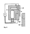
- 1 and 2 each show a schematic cross section through part of a continuous casting installation according to the invention with a cast strand.
- the electromagnetic continuous casting plants shown in FIGS. 1 and 2 have an inductor 8, a coolant tank 3 with coolant nozzles 2 and a screen 9.
- the system shown in Figure 1 has a body 1 which is attached to the coolant tank 3 on its side facing away from the cast strand 10. The coolant emerges from the coolant container 3 and flows through an opening between the inductor 8 and the screen 9 onto the surface of the cast strand 10.
- the cast strand 10 consists of the aluminum alloy AA 3004 and has a rectangular cross section of 500 mm x 1600 mm. Approx. 600 liters of coolant are applied to the cast strand surface every minute.
- the coolant container 3 contains a mixture of water and NaHCOs in a weight fraction of approx. 0.3%. After the pouring phase, with a cast strand length of 100 mm, the addition of NaHC03 in the coolant tank 3 is stopped.
- a partial flow from the coolant tank 3 is directed through a coolant nozzle 2 to a first measuring point of the body 1.
- a temperature sensor 5 is installed under the impact area. This directly measures the surface temperature and is of the type of the temperature probe described in EP-A-0 162 809.
- An analog temperature sensor 5 ' is installed vertically below this at a distance of 70 mm. This second measuring point lies in the outflow area of the coolant which has impinged on the first measuring point.
- the area of the body 1 comprising the two temperature sensors 5, 5 ′ is heated in a controlled manner by a built-in heating device 4, which is designed as an electrical resistance heater. The heating power required to maintain a constant mean temperature is measured and the corresponding information is transmitted to a data processing system 7.
- the mean temperature is calculated from the temperature values measured with the temperature sensors 5 and 5 'and transmitted to the data processing system 7.
- the cast strand surface charged with the coolant has a temperature of approximately 420 ° C. in the area of impact.
- the first measuring point of the body 1 is kept at a temperature of about 450 ° C. in the temperature sensor 5.
- a CO 2 gas is split off from the NaHCO 3 contained in the coolant in the pouring phase, which forms a film there, which considerably reduces the cooling capacity compared to pure water.
- the coolant tank 3 is provided on the supply side with actuators 6, which act on the one hand on the NaHC0 3 dosage and on the other hand influence the water pressure.
- the actuators 6 are connected to the data processing system 7 and are controlled by this on the basis of a comparison of the information coming from the heating device 4 and from the temperature sensors 5, 5 ′ with predetermined reference variables.
- the embodiment shown in FIG. 2 uses the screen 9 as the body 1.
- the measuring points are arranged on the inside of the screen 9 in such a way that they are struck by the coolant which flows from the coolant tank 3 to the cast strand 10.
- Temperature sensors 5 are installed at the measuring point under the surface of the screen 9.
- the inductor 8 acts as a heating device 4, which keeps the screen 9 at an equilibrium temperature at constant current and constant cooling capacity of the coolant.
- the temperature sensors 5 are connected to a data processing system 7, which in turn is connected to the actuators 6 attached to the coolant tank 3 and receives information about the current intensity prevailing in the inductor 8.
Landscapes
- Engineering & Computer Science (AREA)
- Mechanical Engineering (AREA)
- Continuous Casting (AREA)
- Yarns And Mechanical Finishing Of Yarns Or Ropes (AREA)
- Application Of Or Painting With Fluid Materials (AREA)
- Heat Treatments In General, Especially Conveying And Cooling (AREA)
- Organic Low-Molecular-Weight Compounds And Preparation Thereof (AREA)
Description
- Die Erfindung betrifft ein Verfahren zur Regelung der Abkühlgeschwindigkeit eines aus einer Stranggiesskokille austretenden Gussstranges, der durch Aufbringen eines fluiden Kühlmittels unmittelbar auf die Strangoberffäche gekühlt wird, durch Regelung der Kühlleistung des Kühlmittels, umfassend fortlaufendes Messen der Kühlleistung, Vergleichen dieser Messwerte mit der Führungsgrösse der geforderten Kühlleistung und Steuerung der Zusammensetzung und/oder der zeitbezogenen Abgabemenge des Kühlmittels zur Angleichung an die Führungsgrösse, wobei die Messung der Kühlleistung unter Verwendung von nicht mit dem Gussstrang in Berührung gekommenen Kühlmittel an mindestens einer Stelle ausserhalb des Gussstranges durchgeführt wird.
- Zudem liegt im Rahmen der Erfindung eine Stranggiessanlage mit auf die Zusammensetzung und/oder die zeitbezogene Menge des abgegebenen Kühlmittels einwirkenden Stellgliedem, mit mindestens einer Kühlmitteldüse, welche mit einem Kühlmittelbehälter in Verbindung steht.
- Ein Verfahren sowie eine Vorrichtung zu dessen Durchführung der eingangs erwähnten Gattung geht aus der EP-A 0 054 867 als bekannt hervor.
- Beim Stranggiessen mit direkter Kühlung wird dem aus der Kokille austretenden Gussstrang durch Beaufschlagen der Strangoberfläche mit einem fluiden Kühlmittel unmittelbar unterhalb der Kokille Wärme entzogen. Die Wärmeentzugsrate und die resultierende Abkühlgeschwindigkeit beeinflussen in hohem Masse das Gefüge des Gussstrangs und insbesondere die Ausgestaltung der Gussstrangoberfläche. Gewöhnlich wird vom Giessbeginn bis zum Giessabbruch das Kühlmittel in einer zeitbezogen konstanten Menge abgegeben. Um den speziellen Gegebenheiten in der Angiessphase Rechnung zu tragen, wurde eine Reihe von Verfahren und Vorrichtungen entwickelt, welche die Kühlintensität in dieser Phase verändern -- in der Regel reduzieren -- helfen. Insbesondere für das berührungslose, vertikal abwärts gerichtete Stranggiessen von Metallen im elektromagnetischen Wechselfeld wird beispielsweise in der EP-B-0 015 870 eine feine Regulierung des Kühlmittel-Auftreffwinkels und -Auftreffbereichs durch eine kontrollierte Umlenkung des Kühimitteistrahis vorgeschlagen, um damit die Erstarrungsbedingungen den verschiedenen Giesslegierungen und Giessgeschwindigkeiten optimal anpassen zu können. In der EP-B-062 606 ist zur Vermeidung einer konvexen Wölbung des Strangfusses durch nicht-stationäre Kühlbedingungen in der Angiessphase eine parallel zur Giessstrangachse bewegbare Ablenkfläche mit Ausnehmungen vorgesehen, welche zumindest in der Angiessphase in die Bahn des Kühlmittels eingeschoben wird. Die EP-B-0 082 810 beschreibt eine weitere Methode zur Verminderung der bei zu schroffer Abkühlung des Stranges auftretenden Wölbung des Strangfusses. Dabei wird dem Kühlmittel zumindest während der Angiessphase eine Substanz beigemischt, die beim Auftreffen auf die heisse Strangoberfläche ein Gas als Zersetzungsprodukt abgibt, welches dort einen den Wärmeabfluss vermindernden Isolierfilm bitdet. Aus der EP-A-0 127 577 ist zudem ein Verfahren zum Stranggiessen bekannt, bei welchem der entstehende Strang mittels Kohlendioxid enthaltendem Wasser gekühlt wird, wobei die zugesetzte Menge an Kohlendioxid während des .Anfahrvorganges konstant gehalten, jedoch seine Konzentration innerhalb des Kühlmittels durch Erhöhung des Wasserzuflusses vermindert und gleichzeitig der thermiche Kontakt zwischen Strangoberfläche und Kühl mittel erhöht wird. Die Zufuhr des Kohlendioxids soll dabei nach dem Anfahrvorgang oder nach Unterschreiten eines bestimmten Kohlendioxid-Konzentrationswertes unterbrochen werden.
- Bei all diesen Verfahren wird jedoch nicht berücksichtigt, dass Schwankungen der Kühlmittelqualität beispielsweise durch Schwankungen der Temperatur oder der Verunreinigung, sowie Druckunterschiede auftreten können, welche die Kühlleistung erheblich beeinflussen.
- Zur teilweisen Beseitigung dieses Mangels ist aus der DE-A-19 41 816 ein Verfahren zur Regelung der Abkühlungsgeschwindigkeit von langgestreckten, sich bewegenden, heissen Gegenständen aus Aluminium oder Aluminiumlegierungen -- insbesondere von aus der Kokille austretenden Gusssträngen - bekannt, bei welchen die Regelung der Abkühlungsgeschwindigkeit in Abhängigkeit von der Oberflächentemperatur des sich bewegenden Gegenstandes erfolgt. Im Beispiel einer Kühlung mittels eines Flüssikeits-Luft-Gemisches wird dort vorgeschlagen, die Wassermenge, den Wasserdruck sowie die Gemischzusammensetzung nach Massgabe der gemessenen Oberflächentemperatur zu beeinflussen. Da speziell bei Aluminiumwerkstoffen die Anwendung eines Strahlungspyrometers infolge unterschiedlichen Emissionsvermögens des Aluminiums und des Aluminiumoxids bei schwankender Oxidhautdicke problematisch ist, wird dort ein Stechpyrometer eingesetzt.
- Solche Oberflächenmessungen sind jedoch aufwendig und störungsanfällig. Die Platzverhältnisse bei Stranggiessanlagen erschweren zudem die Installation dieser Messeinrichtungen. Insbesondere beim Giessen von Metallen im elektromagnetischen Wechselfeld stören solche in unmittelbarer Nähe der Gussstrangoberfläche angeordneten Vorrichtungen den Giessablauf.
- Der Erfindung liegt daher die Aufgabe zugrunde, ein Verfahren der eingangs genannten Gattung zu schaffen, mittels welchem der Beitrag der Kühlleistung des Kühlmittels zur Regelung der Abkühlgeschwindigkeit des Gussstranges kontrolliert werden kann, ohne die unmittelbare Umgebung dieses Gussstranges zu stören bzw. durch diese gestört zu werden.
- Weiter soll eine Stranggiessanlage geschaffen werden, welche zur Durchführung dieses Verfahrens geeignet ist.
- In bezug auf das Verfahren wird die Aufgabe erfindungsgemäss dadurch gelöst, dass ein Teil des Kühlmittels auf mindestens eine ausserhalb des Gussstranges befindliche Messstelle definierter Temperatur oberhalb der Kühlmitteltemperatur gelenkt wird und dort die Kühlleistung mittels Temperaturmessungen überwacht wird.
- Im Falle eines geschlossenen Kühlmittelkreislaufs darf das zur Messung verwendete Kühlmittel innerhalb desselben Zyklus nicht bereits mit dem Gussstrang in Berührung gekommen sein.
- Das Kühlmittel kann nach der Messung der Gussstrangoberfläche zugeführt oder direkt abgeführt bzw. rezykliert werden.
- Abweichungen von einem vorgegebenen soll-Verlauf der gemessenen Temperatur lösen eine Korrektur der Kühlmittelzusammensetzung und/oder des Kühlmitteldrucks aus. Besonders günstig ist es, die Messstellentemperatur möglichst nahe der Oberflächentemperatur des Gussstrangs im Bereich des Kühlmittelaufpralls zu wählen. Die Abweichung der absoluten Temperaturen soll 20% jedenfalls nicht überschreiten. Damit kann die Gefahr grosser, temperaturbedingter Unterschiede im qualitativen Kühlverhalten eingeschränkt werden.
- Eine zweckmässige Ausführung besteht darin, den zur Messung bestimmten Teil des Kühlmittels auf einen lokal kontrolliert beheizten Körper zu lenken. Dabei kann die Heizung kontinuierlich oder in definierten Intervallen auf den als Messstelle dienenden Bereich des Körpers einwirken. Zur Erfüllung der hohen Anforderungen der Kühlleistungs-Messung haben sich folgende beiden Methoden als besonders geeignet erwiesen: die Temperatur der mit dem Kühlmittel beaufschlagten Messstelle wird konstant gehalten, die hierfür benötigte Heizleistung wird gemessen und mit einer vorgegebenen Führungsgrösse verglichen, wonach das Kühlmittel nach Massgabe der Abweichung beeinflusst wird. Die zweite Methode besteht darin, die Messstelle während einem vorgegebenen Zeitintervall nicht oder nur mit reduzierter Leistung zu beheizen und den sich dabei einstellenden Temperaturabfall als Mass für die aktuelle Kühlmittelleistung zu verwenden. Zwischen diesen Intervallen wird der als Messstelle dienende Bereich des Körpers wieder auf die ursprüngliche Temperatur geheizt.
- Ein bevorzugtes Verfahren im Rahmen der Erfindung benutzt sowohl Messstellen, in deren Bereich das Kühlmittel direkt auftrifft, als auch solche in einer Rieselzone, in welcher das bereits aufgetroffene Kühlmittel der Körperobertläche entlang, im wesentlichen parallel zu dieser, abfliesst. Informationen aus diesen unterschiedlichen Kühlzonen ermöglichen zusätzliche Rückschlüsse, welche dazu dienen, die verschiedenen Einflussgrössen der Kühlmittelleistung gezielt zu korrigieren.
- Das erfingunsgemässe Verfahren ist bevorzugt anzuwenden auf die Steuerung der Abkühlgeschwindigkeit eines aus einer Stranggiesskokille austretenden Gussstranges, der durch Aufbringen solcher Kühlmittel unmittelbar auf die Strangoberfläche gekühlt wird, welche hierbei ein Gas freisetzen. Die in der Regel auftretende Reduktion der Kühlmittelleistung durch das freigesetzte Gas wird bei den Messungen in diesem Verfahren besonders wirklichkeitsnah erfasst.
- Der Vorteil der räumlichen Trennung der Giesszone und der Messzone im erfindungsgemässen Verfahren kommen bei seiner Anwendung auf das berührungslose Stranggiessen von Metallen im elektromagnetischen Wechselfeld besonders zur Geltung. Da der Gussstrang hierbei praktisch ausschliesslich durch das fluide Kühlmittel zur Erstarrung gebracht wird, ist eine Regelung der Leistung derselben von höchster Bedeutung.
- Die Besonderheiten der Oberfläche von Gusssträngen aus Aluminium und Aluminiumlegierungen prädestinieren die Anwendung dieses von der Gussstrangoberfläche unabhängigen Regelverfahrens.
- In einer bevorzugten Ausführung der erfindungsgemässen Stranggiessanlage ist der die Messstelle tragende Körper auf der dem Gussstrang abgewandten Seite des Kühlmittelbehälters angebracht. Der Körper kann jedoch auch so positioniert oder in konventionelle Bestandteile der Stranggiessanlage eingebaut werden, dass zumindest ein Teil des Kühlmittels auf seinem Weg Kühlmittelbehälter zur Gussstrangoberfläche auf die Messstelle trifft.
- In bezug auf die Vorrichtung besteht die erfindungsgemässe Lösung der Aufgabe darin, eine Stranggiessanlage mit auf die Zusammensetzung und/oder die zeitbezogene Menge des abgegebenen Kühlmittels einwirkenden Stellgliedem mit einer Regeleinrichtung auszustatten.
- Erfindungsgemäss wird die Aufgabe dadurch gelöst, dass mindestens eine der Kühlmitteldüsen auf eine Messstelle eines Körpers mit guter thermischer Leitfähigkeit gerichtet ist, wobei eine auf die Messstelle des Körpers einwirkende Heizvorrichtung sowie mindestens ein unter der Oberfläche der Messstelle des Körpers eingebauter Temperaturfühler vorgesehen ist, und wobei Temperaturfühler, Heizvorrichtung und Stellglieder . mit einer Datenverarbeitungsanlage in Verbindung stehen.
- Die Heizvorrichtung kann beispielsweise als elektrische Widerstandsheizung oder als Induktionsspule ausgebildet sein. Der als Messstelle des Körpers bestimmte Bereich muss nicht in jeder Ausführung in der Messposition beheizt werden können; im Rahmen der Erfindung liegen auch Vorrichtungen, in welchen die Messstellen zur Beheizung in eine von der Messposition abweichende Heizposition gebracht werden können.
- Eine besonders zweckmässige Ausführung der Stranggiessanlage weist im Messstellen-Körper zwei eingebaute Temperaturfühler auf, welche in einem gegenseitigen Abstand von 20 bis 200 mm derart angeordnet sind, dass eine Kühlmitteldüse direkt auf einen dieser Temperaturfühler gerichtet ist und der andere in der Richtung des hiervon abströmenden Kühlmittels liegt. Die Oberfläche des Körpers ist hierbei bevorzugt so gestaltet, dass die Bahn des auftreffenden und abströmenden Kühlmittels in etwa der entsprechenden Bahn des Kühlmittels beim Gussstrang gleicht.
- Ist die erfindungsgemässe Stranggiessanlage zum Giessen von Barren mit rechteckigem Querschnitt - beispielsweise Bändern - bestimmt, so ist es vorteilhaft, sowohl im Bereich der Querschnittsecken, als auch im Bereich der Mitte der Querschnittslängsseiten, Messstellen-tragende Körper anzuordnen. Insbesondere aufgrund örtlich unterschiedlicher Druckverhältnisse des Kühlmittels auftretende Abweichungen der Kühlmittelleistung können hiermit erfasst und bei der Optimierung des Kühlmittelzustandes berücksichtigt werden.
- Weitere Vorteile, Merkmale und Einzelheiten der Erfindung ergeben sich aus der nachfolgenden Beschreibung bevorzugter Ausführungsbeispiele sowie anhand der Zeichnung; diese zeigt in den Figuren 1 und 2 je einen schematisierten Querschnitt durch einen Teil einer erfindungsgemässen Stranggiessanlage mit einem Gussstrang.
- Die in den Figuren 1 und 2 dargestellten elektromagnetischen Stranggiessanlagen weisen einen Induktor 8, ein Kühlmittelbehälter 3 mit Kühlmitteldüsen 2 und einen Schirm 9 auf. Die in Figur 1 dargestellte Anlage weist einen Körper 1 auf, welcher am Kühlmittelbehälter 3 auf seiner dem Gussstrang 10 abgewandten Seite befestigt ist. Das Kühlmittel tritt aus dem Kühlmittelbehälter 3 und strömt durch eine Oeffnung zwischen dem Induktor 8 und dem Schirm 9 auf die Oberfläche des Gussstranges 10.
- Der Gusstrang 10 besteht aus der Aluminiumlegierung AA 3004 und weist einen rechteckigen Querschnitt von 500 mm x 1600 mm auf. Auf die Gussstrangoberfläche werden pro Minute ca. 600 Liter Kühlmittel aufgebracht.
- Der Kühlmittelbehälter 3 enthält in der Angiessphase ein Gemisch aus Wasser und NaHCOs in einem Gewichtsanteil von ca. 0.3 %. Nach Abschluss der Angiessphase, bei einer Gussstranglänge von 100 mm, wird die Zugabe von NaHC03 in den Kühlmittelbehälter 3 abgestellt.
- Ein Teilstrom aus dem Kühlmittelbehälter 3 wird durch eine Kühlmitteldüse 2 auf eine erste Messstelle des Körpers 1 gelenkt. Unter dem Aufprallbereich ist ein Temperaturfühler 5 eingebaut. Dieser misst unmittelbar die Oberflächentemperatur und ist vom Typus der in EP-A-0 162 809 beschriebenen Temperatursonde. In einem Abstand von 70 mm hierzu ist vertikal darunter ein analoger Temperaturfühler 5' eingebaut. Diese zweite Messstelle liegt im Abströmbereich des auf die erste Messstelle geprallten Kühlmittels. Der die beiden Temperaturfühler 5, 5' umfassende Bereich des Körper 1 wird durch eine eingebaute Heizvorrichtung 4, die als elektrische Widerstandsheizung gestaltet ist, kontrolliert beheizt. Die zur Aufrechterhaltung einer konstanten Mitteltemperatur benötigte Heizleistung wird gemessen und die entsprechende Information einer Datenverarbeitungsanlage 7 übermittelt. Die Mitteltemperatur wird aus den mit den Temperaturfühlern 5 und 5' gemessenen und der Datenverarbeitungsanlage 7 übermittelten Temperaturwerten errechnet.
- Die mit dem Kühlmittel beaufschlagte Gussstrangoberfläche weist im Auftreffbereich eine Temperatur von etwa 420 °C auf. Die erste Messstelle des Körpers 1 wird beim Temperaturfühler 5 auf einer Temperatur von etwa 450 °C gehalten. Sowohl auf der Gussstrangoberfläche als auch auf der Oberfläche des Körpers 1 wird vom in der Angiessphase im Kühlmittel enthaltenen NaHC03 ein C02-Gas abgespalten, welches dort einen Film bildet, der die Kühlleistung im Vergleich zu reinem Wasser erheblich reduziert. Der Kühlmittelbehälter 3 ist zufuhrseitig mit Stellgliedern 6 versehen, welche zum einen auf die NaHC03-Dosierung einwirken und zum andem den Wasserdruck beeinflussen. Die Stellglieder 6 sind mit der Datenverarbeitungsanlage 7 verbunden und werden von dieser aufgrund eines Vergleichs der von der Heizvorrichtung 4 sowie von den Temperaturfühlern 5,5' stammenden Informationen mit vorgegebenen Führungsgrössen gesteuert.
- Die in der Figur 2 dargestellte Ausführung benutzt den Schirm 9 als Körper 1. Die Messstellen sind auf der Innenseite des Schirms 9 so angebracht, dass sie vom Kühlmittel getroffen werden, welches vom Kühlmittelbehälter 3 zum Gussstrang 10 strömt. Bei der Messstelle unter der Oberfläche des Schirms 9 sind Temperaturfühler 5 eingebaut. Der Induktor 8 wirkt als Heizvorrichtung 4, welche den Schirm 9 bei konstanter Stromstärke und konstanter Kühlleistung des Kühlmittels auf einer Gleichgewichtstemperatur hält. Auch in dieser Ausführung sind die Temperaturfühler 5 mit einer Datenverarbeitungsanlage 7 verbunden, welche ihrerseits mit den am Kühlmittelbehälter 3 angebrachten Stellgliedern 6 in Verbindung steht und Information über die im Induktor 8 herrschende Stromstärke empfängt.
Claims (13)
Priority Applications (1)
| Application Number | Priority Date | Filing Date | Title |
|---|---|---|---|
| AT86810560T ATE50177T1 (de) | 1985-12-09 | 1986-12-04 | Verfahren und vorrichtung zur leitung der abkuehlgeschwindigkeit eines gussstranges. |
Applications Claiming Priority (2)
| Application Number | Priority Date | Filing Date | Title |
|---|---|---|---|
| CH525885 | 1985-12-09 | ||
| CH5258/85 | 1985-12-09 |
Publications (2)
| Publication Number | Publication Date |
|---|---|
| EP0227596A1 EP0227596A1 (de) | 1987-07-01 |
| EP0227596B1 true EP0227596B1 (de) | 1990-02-07 |
Family
ID=4290589
Family Applications (1)
| Application Number | Title | Priority Date | Filing Date |
|---|---|---|---|
| EP86810560A Expired - Lifetime EP0227596B1 (de) | 1985-12-09 | 1986-12-04 | Verfahren und Vorrichtung zur Leitung der Abkühlgeschwindigkeit eines Gussstranges |
Country Status (10)
| Country | Link |
|---|---|
| US (1) | US4756357A (de) |
| EP (1) | EP0227596B1 (de) |
| JP (1) | JPS62137146A (de) |
| AT (1) | ATE50177T1 (de) |
| AU (1) | AU588650B2 (de) |
| CA (1) | CA1275780C (de) |
| DE (1) | DE3668811D1 (de) |
| ES (1) | ES2012770B3 (de) |
| NO (1) | NO166847C (de) |
| ZA (1) | ZA869250B (de) |
Families Citing this family (5)
| Publication number | Priority date | Publication date | Assignee | Title |
|---|---|---|---|---|
| US5918473A (en) * | 1997-05-09 | 1999-07-06 | Alcan International Limited | Method and apparatus for measuring quenchant properties of coolants |
| US6056041A (en) * | 1997-06-12 | 2000-05-02 | Alcan International Limited | Method and apparatus for controlling the temperature of an ingot during casting, particularly at start up |
| US6412543B1 (en) | 2001-03-07 | 2002-07-02 | Nnorthrop Grumman Corporation | Method for controlling solidification rate of a mold-cast structure |
| US7617863B2 (en) * | 2006-08-11 | 2009-11-17 | Rti International Metals, Inc. | Method and apparatus for temperature control in a continuous casting furnace |
| WO2017198500A1 (fr) | 2016-05-17 | 2017-11-23 | Gap Engineering Sa | Moule de coulée semi-continue verticale comportant un dispositif de refroidissement |
Family Cites Families (9)
| Publication number | Priority date | Publication date | Assignee | Title |
|---|---|---|---|---|
| DE882481C (de) * | 1951-07-01 | 1953-07-09 | Boehler & Co A G Geb | Verfahren und Vorrichtung zum Stranggiessen von Eisen und Stahl |
| CH552423A (de) * | 1972-04-18 | 1974-08-15 | Concast Ag | Verfahren und vorrichtung zum steuern des waermeentzuges in kokillen beim stranggiessen. |
| US4006633A (en) * | 1976-04-22 | 1977-02-08 | Bethlehem Steel Corporation | Method and apparatus for determining heat removal from a continuous caster |
| US4166495A (en) * | 1978-03-13 | 1979-09-04 | Aluminum Company Of America | Ingot casting method |
| SU935206A1 (ru) * | 1980-06-02 | 1982-06-15 | Всесоюзный Научно-Исследовательский Институт Автоматизации Черной Металлургии | Устройство дл автоматического определени интенсивности охлаждени слитка в кристаллизаторе установки непрерывной разливки металла |
| DE3048711C2 (de) * | 1980-12-23 | 1991-08-01 | Hamburger Stahlwerke Gmbh, 2103 Hamburg | Verfahren zum Kühlen von Strängen beim Stranggießen von Stahlknüppeln |
| JPS59199155A (ja) * | 1983-04-28 | 1984-11-12 | Sumitomo Heavy Ind Ltd | 連続鋳造設備における鋳片の表面温度制御方法 |
| US4530404A (en) * | 1983-07-07 | 1985-07-23 | Aluminium Pechiney | Process for the electromagnetic casting of metals involving the use of at least one magnetic field which differs from the field of confinement |
| SU1109249A1 (ru) * | 1983-09-27 | 1984-08-23 | Всесоюзный Научно-Исследовательский Институт Автоматизации Черной Металлургии Научно-Производственного Объединения "Черметавтоматика" | Устройство дл контрол толщины оболочки слитка в кристаллизаторе машины непрерывного лить металла |
-
1986
- 1986-11-27 AU AU65765/86A patent/AU588650B2/en not_active Ceased
- 1986-12-02 US US06/936,808 patent/US4756357A/en not_active Expired - Lifetime
- 1986-12-04 DE DE8686810560T patent/DE3668811D1/de not_active Expired - Lifetime
- 1986-12-04 AT AT86810560T patent/ATE50177T1/de active
- 1986-12-04 ES ES86810560T patent/ES2012770B3/es not_active Expired - Lifetime
- 1986-12-04 EP EP86810560A patent/EP0227596B1/de not_active Expired - Lifetime
- 1986-12-05 NO NO864891A patent/NO166847C/no unknown
- 1986-12-05 CA CA000524672A patent/CA1275780C/en not_active Expired - Lifetime
- 1986-12-08 ZA ZA869250A patent/ZA869250B/xx unknown
- 1986-12-09 JP JP61293334A patent/JPS62137146A/ja active Pending
Also Published As
| Publication number | Publication date |
|---|---|
| US4756357A (en) | 1988-07-12 |
| ZA869250B (en) | 1987-11-25 |
| ES2012770B3 (es) | 1990-04-16 |
| NO864891L (no) | 1987-06-10 |
| AU6576586A (en) | 1987-06-11 |
| AU588650B2 (en) | 1989-09-21 |
| DE3668811D1 (de) | 1990-03-15 |
| NO166847C (no) | 1991-09-11 |
| ATE50177T1 (de) | 1990-02-15 |
| EP0227596A1 (de) | 1987-07-01 |
| JPS62137146A (ja) | 1987-06-20 |
| CA1275780C (en) | 1990-11-06 |
| NO166847B (no) | 1991-06-03 |
| NO864891D0 (no) | 1986-12-05 |
Similar Documents
| Publication | Publication Date | Title |
|---|---|---|
| DE69431178T3 (de) | Verfahren zur thermischen Oberflächenbehandlung eines Stranges | |
| DE69819773T2 (de) | Verfahren und vorrichtung zur herstellung von ferritisch gewalztem stahlband | |
| EP0429394A1 (de) | Kühlen von gegossenen Strängen | |
| EP1412543A1 (de) | Verfahren zur kühlung von werkstücken insbesondere von profilwalzprodukten aus schienenstählen | |
| EP0786531A1 (de) | Verfahren zum Umschmelzen von Metallen zu einem Strang sowie Vorrichtung dafür | |
| DE69808295T2 (de) | Verfahren und vorrichtung zur oberflächentemperaturkontrolle eines blockes während des giessens und insbesondere während des angiessens | |
| EP0746434B1 (de) | Verfahren und vorrichtung zum kühlen schmelzflüssigen stahls | |
| EP0227596A1 (de) | Verfahren und Vorrichtung zur Leitung der Abkühlgeschwindigkeit eines Gussstranges | |
| DE3125315A1 (de) | "kuehlverfahren" | |
| DE60109310T2 (de) | Kontrolle des wärmestroms in einer stranggiessanlage | |
| DE69319285T2 (de) | Verfahren zum Wärmebehandeln von Walzdraht | |
| DE2501868A1 (de) | Verfahren zur regelung und ueberwachung des stranggiessens von stahl und vorrichtung zur durchfuehrung des verfahrens | |
| WO2025027110A1 (de) | Induktive schmelzanlage mit automatischer steuerung | |
| DE3641617A1 (de) | Verfahren zum regeln von stranggiessbedingungen | |
| EP0033307B1 (de) | Verfahren zum kontinuierlichen Messen der Strangoberflächentemperatur eines Gussstranges sowie Einrichtung zur Durchführung des Verfahrens | |
| EP1356882A1 (de) | Vorrichtung zur Herstellung von Pulvermetall | |
| EP0110817B1 (de) | Einrichtung zum Ermitteln der Lage des Giessspiegels | |
| DE3706636C2 (de) | ||
| DE1752297B2 (de) | Einrichtung zum selbsttaetigen aufrechterhalten einer vorgegebenen temperatur in bewegtem walzgut | |
| CH646352A5 (en) | Apparatus for regulating the secondary cooling in a continuous-casting installation with batchwise smelt supply via a tundish | |
| DE19916190C2 (de) | Verfahren und Vorrichtung zum Stranggießen von Brammen | |
| DE2746284B2 (de) | Verfahren zum Stranggießen dünner Drähte aus Metall oder einer Legierung | |
| EP1013362B1 (de) | Verfahren und Vorrichtung zum Stranggiessen von Brammen | |
| EP3934822B1 (de) | Verfahren zur herstellung eines metallischen bandes oder blechs | |
| DE3009697A1 (de) | Verfahren zur automatischen steuerung des betriebszustandes der kokille von metallstranggussanlagen |
Legal Events
| Date | Code | Title | Description |
|---|---|---|---|
| PUAI | Public reference made under article 153(3) epc to a published international application that has entered the european phase |
Free format text: ORIGINAL CODE: 0009012 |
|
| AK | Designated contracting states |
Kind code of ref document: A1 Designated state(s): AT BE CH DE ES FR GB IT LI LU NL SE |
|
| 17P | Request for examination filed |
Effective date: 19871204 |
|
| 17Q | First examination report despatched |
Effective date: 19890109 |
|
| ITF | It: translation for a ep patent filed | ||
| GRAA | (expected) grant |
Free format text: ORIGINAL CODE: 0009210 |
|
| AK | Designated contracting states |
Kind code of ref document: B1 Designated state(s): AT BE CH DE ES FR GB IT LI LU NL SE |
|
| REF | Corresponds to: |
Ref document number: 50177 Country of ref document: AT Date of ref document: 19900215 Kind code of ref document: T |
|
| REF | Corresponds to: |
Ref document number: 3668811 Country of ref document: DE Date of ref document: 19900315 |
|
| RAP2 | Party data changed (patent owner data changed or rights of a patent transferred) |
Owner name: ALUSUISSE-LONZA SERVICES AG |
|
| REG | Reference to a national code |
Ref country code: CH Ref legal event code: PUE Owner name: ALUSUISSE-LONZA SERVICES AG 8034 ZUERICH ZUSTELLAD |
|
| GBT | Gb: translation of ep patent filed (gb section 77(6)(a)/1977) | ||
| ET | Fr: translation filed | ||
| REG | Reference to a national code |
Ref country code: GB Ref legal event code: 732 |
|
| PLBE | No opposition filed within time limit |
Free format text: ORIGINAL CODE: 0009261 |
|
| STAA | Information on the status of an ep patent application or granted ep patent |
Free format text: STATUS: NO OPPOSITION FILED WITHIN TIME LIMIT |
|
| BECN | Be: change of holder's name |
Effective date: 19900207 |
|
| ITTA | It: last paid annual fee | ||
| 26N | No opposition filed | ||
| EPTA | Lu: last paid annual fee | ||
| EAL | Se: european patent in force in sweden |
Ref document number: 86810560.2 |
|
| PGFP | Annual fee paid to national office [announced via postgrant information from national office to epo] |
Ref country code: GB Payment date: 19951124 Year of fee payment: 10 |
|
| PGFP | Annual fee paid to national office [announced via postgrant information from national office to epo] |
Ref country code: LU Payment date: 19951201 Year of fee payment: 10 |
|
| PGFP | Annual fee paid to national office [announced via postgrant information from national office to epo] |
Ref country code: BE Payment date: 19951208 Year of fee payment: 10 |
|
| PGFP | Annual fee paid to national office [announced via postgrant information from national office to epo] |
Ref country code: SE Payment date: 19951211 Year of fee payment: 10 Ref country code: AT Payment date: 19951211 Year of fee payment: 10 |
|
| PGFP | Annual fee paid to national office [announced via postgrant information from national office to epo] |
Ref country code: NL Payment date: 19951213 Year of fee payment: 10 |
|
| PGFP | Annual fee paid to national office [announced via postgrant information from national office to epo] |
Ref country code: ES Payment date: 19951215 Year of fee payment: 10 |
|
| PGFP | Annual fee paid to national office [announced via postgrant information from national office to epo] |
Ref country code: FR Payment date: 19951227 Year of fee payment: 10 |
|
| PGFP | Annual fee paid to national office [announced via postgrant information from national office to epo] |
Ref country code: DE Payment date: 19960118 Year of fee payment: 10 |
|
| PGFP | Annual fee paid to national office [announced via postgrant information from national office to epo] |
Ref country code: CH Payment date: 19960228 Year of fee payment: 10 |
|
| PG25 | Lapsed in a contracting state [announced via postgrant information from national office to epo] |
Ref country code: LU Free format text: LAPSE BECAUSE OF NON-PAYMENT OF DUE FEES Effective date: 19961204 Ref country code: GB Effective date: 19961204 Ref country code: AT Effective date: 19961204 |
|
| PG25 | Lapsed in a contracting state [announced via postgrant information from national office to epo] |
Ref country code: SE Effective date: 19961205 |
|
| PG25 | Lapsed in a contracting state [announced via postgrant information from national office to epo] |
Ref country code: LI Effective date: 19961231 Ref country code: CH Effective date: 19961231 Ref country code: BE Effective date: 19961231 |
|
| BERE | Be: lapsed |
Owner name: ALUSUISSE-LONZA SERVICES A.G. Effective date: 19961231 |
|
| PG25 | Lapsed in a contracting state [announced via postgrant information from national office to epo] |
Ref country code: NL Effective date: 19970701 |
|
| GBPC | Gb: european patent ceased through non-payment of renewal fee |
Effective date: 19961204 |
|
| REG | Reference to a national code |
Ref country code: CH Ref legal event code: PL |
|
| PG25 | Lapsed in a contracting state [announced via postgrant information from national office to epo] |
Ref country code: FR Effective date: 19970829 |
|
| NLV4 | Nl: lapsed or anulled due to non-payment of the annual fee |
Effective date: 19970701 |
|
| PG25 | Lapsed in a contracting state [announced via postgrant information from national office to epo] |
Ref country code: DE Effective date: 19970902 |
|
| EUG | Se: european patent has lapsed |
Ref document number: 86810560.2 |
|
| REG | Reference to a national code |
Ref country code: FR Ref legal event code: ST |
|
| PG25 | Lapsed in a contracting state [announced via postgrant information from national office to epo] |
Ref country code: ES Free format text: LAPSE BECAUSE OF NON-PAYMENT OF DUE FEES Effective date: 19971205 |
|
| REG | Reference to a national code |
Ref country code: ES Ref legal event code: FD2A Effective date: 19980113 |
|
| PG25 | Lapsed in a contracting state [announced via postgrant information from national office to epo] |
Ref country code: IT Free format text: LAPSE BECAUSE OF NON-PAYMENT OF DUE FEES Effective date: 20051204 |