EP0226877A2 - Méthode pour transmettre des signaux binaires, émetteur et récepteur de signaux binaires pour la mise en oeuvre de cette méthode et support d'enregistrement utilisant cette méthode - Google Patents
Méthode pour transmettre des signaux binaires, émetteur et récepteur de signaux binaires pour la mise en oeuvre de cette méthode et support d'enregistrement utilisant cette méthode Download PDFInfo
- Publication number
- EP0226877A2 EP0226877A2 EP86116608A EP86116608A EP0226877A2 EP 0226877 A2 EP0226877 A2 EP 0226877A2 EP 86116608 A EP86116608 A EP 86116608A EP 86116608 A EP86116608 A EP 86116608A EP 0226877 A2 EP0226877 A2 EP 0226877A2
- Authority
- EP
- European Patent Office
- Prior art keywords
- bit
- full
- bit signal
- wave
- audio
- Prior art date
- Legal status (The legal status is an assumption and is not a legal conclusion. Google has not performed a legal analysis and makes no representation as to the accuracy of the status listed.)
- Withdrawn
Links
Images

Classifications
-
- G—PHYSICS
- G11—INFORMATION STORAGE
- G11B—INFORMATION STORAGE BASED ON RELATIVE MOVEMENT BETWEEN RECORD CARRIER AND TRANSDUCER
- G11B27/00—Editing; Indexing; Addressing; Timing or synchronising; Monitoring; Measuring tape travel
- G11B27/10—Indexing; Addressing; Timing or synchronising; Measuring tape travel
- G11B27/19—Indexing; Addressing; Timing or synchronising; Measuring tape travel by using information detectable on the record carrier
- G11B27/28—Indexing; Addressing; Timing or synchronising; Measuring tape travel by using information detectable on the record carrier by using information signals recorded by the same method as the main recording
- G11B27/32—Indexing; Addressing; Timing or synchronising; Measuring tape travel by using information detectable on the record carrier by using information signals recorded by the same method as the main recording on separate auxiliary tracks of the same or an auxiliary record carrier
- G11B27/322—Indexing; Addressing; Timing or synchronising; Measuring tape travel by using information detectable on the record carrier by using information signals recorded by the same method as the main recording on separate auxiliary tracks of the same or an auxiliary record carrier used signal is digitally coded
- G11B27/323—Time code signal, e.g. on a cue track as SMPTE- or EBU-time code
-
- G—PHYSICS
- G11—INFORMATION STORAGE
- G11B—INFORMATION STORAGE BASED ON RELATIVE MOVEMENT BETWEEN RECORD CARRIER AND TRANSDUCER
- G11B20/00—Signal processing not specific to the method of recording or reproducing; Circuits therefor
- G11B20/10—Digital recording or reproducing
-
- G—PHYSICS
- G11—INFORMATION STORAGE
- G11B—INFORMATION STORAGE BASED ON RELATIVE MOVEMENT BETWEEN RECORD CARRIER AND TRANSDUCER
- G11B27/00—Editing; Indexing; Addressing; Timing or synchronising; Monitoring; Measuring tape travel
- G11B27/10—Indexing; Addressing; Timing or synchronising; Measuring tape travel
- G11B27/19—Indexing; Addressing; Timing or synchronising; Measuring tape travel by using information detectable on the record carrier
- G11B27/28—Indexing; Addressing; Timing or synchronising; Measuring tape travel by using information detectable on the record carrier by using information signals recorded by the same method as the main recording
- G11B27/30—Indexing; Addressing; Timing or synchronising; Measuring tape travel by using information detectable on the record carrier by using information signals recorded by the same method as the main recording on the same track as the main recording
- G11B27/3027—Indexing; Addressing; Timing or synchronising; Measuring tape travel by using information detectable on the record carrier by using information signals recorded by the same method as the main recording on the same track as the main recording used signal is digitally coded
- G11B27/3036—Time code signal
-
- G—PHYSICS
- G11—INFORMATION STORAGE
- G11B—INFORMATION STORAGE BASED ON RELATIVE MOVEMENT BETWEEN RECORD CARRIER AND TRANSDUCER
- G11B27/00—Editing; Indexing; Addressing; Timing or synchronising; Monitoring; Measuring tape travel
- G11B27/10—Indexing; Addressing; Timing or synchronising; Measuring tape travel
- G11B27/19—Indexing; Addressing; Timing or synchronising; Measuring tape travel by using information detectable on the record carrier
- G11B27/28—Indexing; Addressing; Timing or synchronising; Measuring tape travel by using information detectable on the record carrier by using information signals recorded by the same method as the main recording
- G11B27/32—Indexing; Addressing; Timing or synchronising; Measuring tape travel by using information detectable on the record carrier by using information signals recorded by the same method as the main recording on separate auxiliary tracks of the same or an auxiliary record carrier
- G11B27/322—Indexing; Addressing; Timing or synchronising; Measuring tape travel by using information detectable on the record carrier by using information signals recorded by the same method as the main recording on separate auxiliary tracks of the same or an auxiliary record carrier used signal is digitally coded
- G11B27/324—Duty cycle modulation of control pulses, e.g. VHS-CTL-coding systems, RAPID-time code, VASS- or VISS-cue signals
-
- G—PHYSICS
- G11—INFORMATION STORAGE
- G11B—INFORMATION STORAGE BASED ON RELATIVE MOVEMENT BETWEEN RECORD CARRIER AND TRANSDUCER
- G11B2220/00—Record carriers by type
- G11B2220/90—Tape-like record carriers
Definitions
- the invention relates to a method for transmitting bit signals that follow one another with a time interval, for encoding and decoding a recording medium, in particular video tape, with at least one track for basic audio and / or video information that is transmitted in a predetermined basic frequency range, and on a bit signal generator and a bit signal receiver for carrying out this method and on a recording medium which has been recorded using this transmission method.
- the bit signals are used to record an identification code on a video tape, with the aid of which it is possible to identify the respective video image.
- This identification code also referred to as the "time code”
- This identification code is recorded on the synchronous track in a form of pulse polarity modulation, that is, depending on the bit information, as a positive or negative magnetic pulse.
- the repetition frequency is between 20 and 30 Hz.
- a strong crosstalk on the useful signal track is accepted. It also occurs when several of the same name Pulses follow one another, a shift in the DC mean value, which can lead to disturbances. Since the synchronizing pulses normally recorded on the synchronous track all have the same polarity, the video tape encoded with the pulse polarity-modulated bit signals can only be played back on specially adapted devices, but not on the devices of normal design already on the market.
- bit signals by full sine waves, which start with the positive or negative half-wave depending on the bit information. They are passed as measurement or computing data via their own transmission system (US Pat. No. 3,244,986) or superimposed on a carrier wave with the same frequency (DE-PS 25 31 837).
- the invention has for its object to provide a method of the type described in the introduction, in which the interference emanating from the bit signals during transmission can be kept substantially lower.
- each bit signal is formed by a small number of full waves, which start with the positive or negative half-wave depending on the bit information, and in that the frequency of the fundamental wave of the full wave lies outside the basic frequency range.
- the time integral for each of these bit signals is 0. No interference in the area of the repetition frequency is therefore to be expected. There is no shift in the DC mean.
- the fundamental oscillation of the full wave is the main cause of interference. In a specific case, this frequency can be chosen in such a way that it covers the useful frequency ranges of other systems which could cause crosstalk into it, bother little or not at all. If the frequency range of the basic information is known, the frequency of the full wave can be defined outside this frequency range.
- bit signals formed by the full wave can also be evaluated easily and in particular by means of a microprocessor. Because this determination of the bit information only needs to be checked whether a positive or negative half-wave occurs first. This also results in redundancy because the information of the first half-wave can be confirmed with the help of the second half-wave.
- the full waves are preferably not square waves but full sine waves. Neither subharmonics nor harmonics can occur. Since the frequency of the full sine wave lies outside the basic frequency range, there are no interference-effective frequencies at all.
- each bit signal consists of only one full wave, in particular a full sine wave. This bit signal has a very low energy, but is completely sufficient for information transmission.
- the frequency of the full wave should be above the hearing threshold.
- the bit signals are recorded on a track of a video tape in each case for the change of picture or field and form block-by-block an identification code.
- the frequency of the full wave can be selected so that neither the audio frequency range nor the video frequency range are disturbed.
- the length of the video tape in each case can be determined by the identification code or mark the existing video image exactly. Since the repetition frequency of the bit signals does not cause interference, it can also be greater than 20 to 30 Hz, for example assigned to the field change, and be 50 Hz. This allows more extensive information to be transmitted for a time code with blocks of seconds.
- the bit signals are advantageously recorded on the synchronous track of a video tape and the half-waves of the same polarity are each evaluated as synchronous signals. Because the full waves have a very high frequency compared to the frame rate, the time difference between the first and second half-waves does not play an important role for the synchronization. Therefore, such video tapes provided with an identification code can also be played back on the previously usual video devices if the code is not evaluated.
- bit signals are recorded on one of two adjacent audio tracks of a video tape, the other of which carries an audio signal.
- the usual video tapes designed for stereo operation can therefore be provided with an identification code if mono sound reproduction is sufficient.
- the two audio tracks are arranged so close to each other that crosstalk occurs, the audio frequency and full wave frequency can be kept at a sufficient distance from one another.
- bit signals are recorded together with an audio signal on an audio helical track at a safety distance between the video helical tracks of a video tape.
- Such a mixed recording is possible because of the audio helical track Subordinate audio channel regularly for HiFi conditions! is designed and therefore has a very wide range. !
- the audio channel can have a bandwidth exceeding 18 kHz and the frequency of the full wave can be greater than 18 kHz.
- Particularly favorable h a frequency of the full wave of about 20 kHz at proven. This frequency is sufficiently far above the hearing threshold, but is certainly detected by the usual hi-fi amplifiers.
- a bit signal generator for performing the method is characterized in that a double pulse consisting of two opposing rectangular pulses with a sequence of the rectangular pulses dependent on the bit information can be fed to a sine filter via a controlled switching device for emitting a bit signal.
- the full sine wave is therefore obtained from a rectangular double pulse, which can be easily generated with the aid of a microprocessor or a logic circuit.
- the controlled switching device has three switching paths, via which a medium voltage can be supplied to the sine filter and a higher voltage and a lower voltage or vice versa can be supplied for a predetermined duration in each case for emitting a bit signal i, and that the sine Filter is connected upstream of a decoupling capacitor.
- Such a switching device can be controlled particularly easily with a microprocessor.
- the output of the sine filter can be connected to a feed line for audio signals at a mixing point.
- the mixed signal consisting of audio signal and bit signals can then be picked up and transmitted behind the mixing point.
- the audio signal feed line can be provided with a low-pass filter, which filters out frequencies in the region of the full sine waves. This ensures that the frequency of the full sine wave is outside the audio frequency range.
- a bit signal receiver for carrying out the method is characterized according to the invention by two comparators for determining the positive and negative half-waves of the full wave and by an evaluation circuit which obtains the bit information from the sequence in which the comparators respond.
- the phase position of the half-wave can be determined in a simple manner with the aid of the comparators. Your output signal can be easily evaluated with a logic circuit or a microprocessor.
- the evaluation circuit have two flip-flops, each associated with bit information, each of which can be controlled by a comparator and then generate a pulse of a predetermined duration, and has a logic comparator that only confirms the bit information if the other flip-flop within the pulse duration mentioned appeals. In this way, each bit signal is precisely recognized. Interferences with the frequency of the full wave are rejected as non-information.
- comparators can be preceded by a high-pass filter for separating the full waves from the audio signal. This is the easiest way to separate the two mixed signals again.
- a recording medium which is recorded with bit signals in addition to at least basic information, in particular a video tape, according to the transmission method has the advantage that in addition to basic information tion, for example audio and / or video information, further information is provided which does not interfere with the basic information during playback.
- bit signals should each be spatially assigned to an image or field of the video tape and should form an identification code in blocks.
- a specific video image can be found quickly or the editing of video tapes can be facilitated.
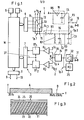
- F ig. 1. shows a bit signal generator 1 and a bit signal receiver 2 provided with an evaluation circuit 3, both of which are controlled by a microprocessor M.
- the microprocessor usually has a computer (CPU), a clock pulse generator, a read-only memory, a variable memory, a data bus, an address bus and a control bus. It has an input device 4, for example a keyboard, and a display device 5, for example a display. It is connected via an interface 6 to the bit signal generator 1, via an interface 7 to the bit signal receiver 2 and via an interface 8 to a control channel 9 leading to a video playback device and a control channel 10 leading to a video recording device.
- the control channels can be formed by electrical connections, by infrared paths or the like.
- the bit signal generator 1 has a switching device 11 with three switching paths 12, 13 and 14, each of which can be controlled by the microprocessor M.
- a line 15 forming the test point Tp. 1 can therefore optionally be connected to the voltage U, half the voltage U / 2 or the zero point 0 of the voltage.
- the line 15 leads to the input of a sine filter 16, which has a coupling capacitor C1, a series resistor R1, a series resistor R2, a series capacitor C2, a series resistor R3 and a series capacitor C3.
- Bit signals B in the form of full sine waves are therefore output at the output which corresponds to test point Tp. 2.
- Fig. 2 illustrates that the frequency range of the audio signal A extends between 20 Hz and 18 kHz, while the frequency of the full sine wave of the bit signal B is 20 kHz. Accordingly, the switching device 11 is controlled and the sine filter 16 is designed such that only a full sine wave with 20 kHz emerges at the output. And the low-pass filter 18 is designed so that frequencies above 18 kHz are filtered out. Since the hearing threshold is 18 kHz and below, this limitation is irrelevant for audio transmission.
- Fig. 3 a section of a video tape 20 is illustrated, the inclined tracks 21 for recording the video signals and in their safety distance tracks 22, which in the known case serve as audio tracks for HiFi transmission, but in the present case the recording of the mixed signal from A. Record B. Furthermore, a synchronous track 23 and two audio tracks 24 and 25 are provided.
- the bit signal B can also be recorded directly on the synchronous track 24.
- the tape can be played in a commercially available playback device because the one half-wave of the full sine wave is recorded as a synchronous signal.
- One audio track 25 can also be used to record the bit signals B. The close proximity to the other audio track 28 is harmless.
- the combined signal A + B recorded on the video tape 20 is recorded at the input 31 of the bit signal receiver 2 and amplified in an amplifier 32 controlled by a controller 35. From the The signal present at the amplifier output 33 (Tp. 3) is filtered out using a high-pass filter 34 and the bit signal B is available at the filter output 36 (test point Tp. 4). An input of two comparators Kl and K2 is fed to each. The other inputs are each supplied with a limit value S 1 or S 2 . If the bit signal B exceeds the limit value S 1 , a signal is output to the flip-flop FF1, and if the value falls below the limit value S 2, a signal to the flip-flop FF2. The outputs of the flip-flops are fed to the interface 7. From there, the flip-flops also receive a reset signal via line 37.
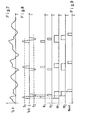
- the switching path 13 is normally closed, so that the voltage U / 2 is present at the test point Tp. 1 (FIG. 4). If a bit signal is to be emitted, which is the case every 20 ms, the switching path 13 is opened and for a short time the switching path 12 and then the switching path 14 or vice versa is closed. In the first case, there is a rectangular alternating pulse with the duration of 50 gs, which contains the log 1 information. In the opposite case, the information is log 0.
- each code which can be used as "timecode" in a manner known per se.
- the transmission of each code is, as shown in FIG. 6, one second each and includes data D, namely mostly with tens and ones digits, time information about hour (h), minute (min) and second (sec), as well as classification information (frame f, user code u), as well as start bits S and end or test bits E.
- data D namely mostly with tens and ones digits, time information about hour (h), minute (min) and second (sec), as well as classification information (frame f, user code u), as well as start bits S and end or test bits E.
- Fig. 7 shows the mixed signal A + B, which occurs when playing the video tape 20 at the input 31 or at the test point Tp. 3.
- the high-pass filter 34 is used to recover the bit signal B at the test point Tp. 4 (FIG. 8) and to compare it with the limit values S 1 and S 2 in the comparators K1 and K2. If these limit values are exceeded or undershot, the comparators emit the pulses illustrated in FIG. 9 in lines K1 and K2. This triggers the flip-flops FF1 and FF2.
- a reset signal is emitted via line 38 when a predetermined running time of the flip-flop that responds first has expired. This also resets the second flip-flop.
- the logical evaluation is carried out in such a way that the microprocessor M operating as a logic comparator checks which flip-flop has responded first and whether the second flip-flop also responds within the time window specified by the first flip-flop. Under this condition, a logic 1 is confirmed if the flip-flop FF1 has responded first and a logic 0 if the flip-flop FF2 has responded first.
- the sine full wave bit signals are particularly suitable, as the exemplary embodiments show, for the identification of video tapes. However, they are also of advantage for many other transmission purposes, for example when bit signals and audio signals are to be transmitted via a channel or in the case of remote data transmission, multiple bit information with different frequencies are to be transmitted or crosstalk to neighboring systems is to be feared at all.
Applications Claiming Priority (2)
| Application Number | Priority Date | Filing Date | Title |
|---|---|---|---|
| DE19853545601 DE3545601A1 (de) | 1985-12-21 | 1985-12-21 | Verfahren zur uebertragung von bitsignalen, bitsignalgeber und bitsignalempfaenger zur durchfuehrung des verfahrens sowie nach dem verfahren bespielter aufzeichnungstraeger |
| DE3545601 | 1985-12-21 |
Publications (2)
| Publication Number | Publication Date |
|---|---|
| EP0226877A2 true EP0226877A2 (fr) | 1987-07-01 |
| EP0226877A3 EP0226877A3 (fr) | 1988-10-19 |
Family
ID=6289265
Family Applications (1)
| Application Number | Title | Priority Date | Filing Date |
|---|---|---|---|
| EP86116608A Withdrawn EP0226877A3 (fr) | 1985-12-21 | 1986-11-28 | Méthode pour transmettre des signaux binaires, émetteur et récepteur de signaux binaires pour la mise en oeuvre de cette méthode et support d'enregistrement utilisant cette méthode |
Country Status (3)
| Country | Link |
|---|---|
| EP (1) | EP0226877A3 (fr) |
| JP (1) | JPS62283458A (fr) |
| DE (1) | DE3545601A1 (fr) |
Families Citing this family (1)
| Publication number | Priority date | Publication date | Assignee | Title |
|---|---|---|---|---|
| CN103811022B (zh) * | 2014-02-18 | 2017-04-19 | 天地融科技股份有限公司 | 一种解析波形的方法和装置 |
Citations (13)
| Publication number | Priority date | Publication date | Assignee | Title |
|---|---|---|---|---|
| NL283021A (fr) * | 1961-09-11 | 1900-01-01 | ||
| GB812934A (en) * | 1956-01-26 | 1959-05-06 | British Tabulating Mach Co Ltd | Improvements in or relating to information storage systems |
| DE1123847B (de) * | 1960-06-01 | 1962-02-15 | Telefunken Patent | Schaltungsanordnung zur Umwandlung der Darstellung von Informationen, insbesondere zur Rueckgewinnung der urspruenglichen Darstellung einer magnetisch aufgezeichneten Information aus Leseimpulsen |
| US3217329A (en) * | 1960-05-03 | 1965-11-09 | Potter Instrument Co Inc | Dual track high density recording system |
| US3244986A (en) * | 1962-10-08 | 1966-04-05 | Ibm | Detection of bi-phase digital signals |
| CH492270A (de) * | 1966-11-07 | 1970-06-15 | Leach Corp | Verfahren zum Aufzeichnen eines binären Datensignals auf einem magnetischen Speichermittel und zum Ablesen und Wiedergeben des aufgezeichneten Datensignals sowie Vorrichtung zur Durchführung des Verfahrens |
| DE2030490A1 (de) * | 1969-06-23 | 1971-03-04 | Nuclear Chicago Corp | Direktdatenspeicheranlage fur Szintillationskamera |
| US3846819A (en) * | 1967-03-31 | 1974-11-05 | Rca Corp | Method for recording two separate signals |
| US3944940A (en) * | 1974-09-06 | 1976-03-16 | Pertec Corporation | Versatile phase-locked loop for read data recovery |
| US4007491A (en) * | 1973-08-27 | 1977-02-08 | Lanier Business Products, Inc. | Dictation-transcription method and system |
| US4167028A (en) * | 1978-04-13 | 1979-09-04 | Recortec, Inc. | Method and an apparatus for time signal encoding/decoding |
| JPS56169274A (en) * | 1980-05-30 | 1981-12-25 | Tdk Corp | Magnetic recording and reproduction system |
| US4543620A (en) * | 1983-03-16 | 1985-09-24 | Victor Company Of Japan, Ltd. | Code generating apparatus |
Family Cites Families (4)
| Publication number | Priority date | Publication date | Assignee | Title |
|---|---|---|---|---|
| CH598722A5 (fr) * | 1974-07-17 | 1978-05-12 | Little Inc A | |
| DE2832337A1 (de) * | 1978-07-22 | 1980-01-31 | Blaupunkt Werke Gmbh | Informationsaufzeichnungs- und informationswiedergabegeraet |
| DE3231562A1 (de) * | 1982-08-25 | 1984-03-01 | Winfried Dipl.-Ing.(FH) 8000 München Walter | Anordnung zum kodieren und dekodieren eines magnetbandes |
| DE3309029C2 (de) * | 1983-03-14 | 1985-05-15 | Winfried Dipl.-Ing.(FH) 8000 München Walter | Verfahren zum Bestimmen der momentanen Bandlänge eines Videomagnetbandes und nach diesem Verfahren bespielte Videomagnetbänder |
-
1985
- 1985-12-21 DE DE19853545601 patent/DE3545601A1/de active Granted
-
1986
- 1986-11-28 EP EP86116608A patent/EP0226877A3/fr not_active Withdrawn
- 1986-12-19 JP JP30184486A patent/JPS62283458A/ja active Pending
Patent Citations (13)
| Publication number | Priority date | Publication date | Assignee | Title |
|---|---|---|---|---|
| GB812934A (en) * | 1956-01-26 | 1959-05-06 | British Tabulating Mach Co Ltd | Improvements in or relating to information storage systems |
| US3217329A (en) * | 1960-05-03 | 1965-11-09 | Potter Instrument Co Inc | Dual track high density recording system |
| DE1123847B (de) * | 1960-06-01 | 1962-02-15 | Telefunken Patent | Schaltungsanordnung zur Umwandlung der Darstellung von Informationen, insbesondere zur Rueckgewinnung der urspruenglichen Darstellung einer magnetisch aufgezeichneten Information aus Leseimpulsen |
| NL283021A (fr) * | 1961-09-11 | 1900-01-01 | ||
| US3244986A (en) * | 1962-10-08 | 1966-04-05 | Ibm | Detection of bi-phase digital signals |
| CH492270A (de) * | 1966-11-07 | 1970-06-15 | Leach Corp | Verfahren zum Aufzeichnen eines binären Datensignals auf einem magnetischen Speichermittel und zum Ablesen und Wiedergeben des aufgezeichneten Datensignals sowie Vorrichtung zur Durchführung des Verfahrens |
| US3846819A (en) * | 1967-03-31 | 1974-11-05 | Rca Corp | Method for recording two separate signals |
| DE2030490A1 (de) * | 1969-06-23 | 1971-03-04 | Nuclear Chicago Corp | Direktdatenspeicheranlage fur Szintillationskamera |
| US4007491A (en) * | 1973-08-27 | 1977-02-08 | Lanier Business Products, Inc. | Dictation-transcription method and system |
| US3944940A (en) * | 1974-09-06 | 1976-03-16 | Pertec Corporation | Versatile phase-locked loop for read data recovery |
| US4167028A (en) * | 1978-04-13 | 1979-09-04 | Recortec, Inc. | Method and an apparatus for time signal encoding/decoding |
| JPS56169274A (en) * | 1980-05-30 | 1981-12-25 | Tdk Corp | Magnetic recording and reproduction system |
| US4543620A (en) * | 1983-03-16 | 1985-09-24 | Victor Company Of Japan, Ltd. | Code generating apparatus |
Non-Patent Citations (1)
| Title |
|---|
| PATENT ABSTRACTS OF JAPAN, Band 6, Nr. 59 (P-110)[937], 16. April 1982; & JP-A-56 169 274 (TOKYO DENKI KAGAKU KOGYO K.K.) 25.12.1981 * |
Also Published As
| Publication number | Publication date |
|---|---|
| DE3545601A1 (de) | 1987-07-02 |
| JPS62283458A (ja) | 1987-12-09 |
| DE3545601C2 (fr) | 1989-04-06 |
| EP0226877A3 (fr) | 1988-10-19 |
Similar Documents
| Publication | Publication Date | Title |
|---|---|---|
| DE2427225C3 (de) | Schaltungsanordnung zur Demodulation digitaler Information | |
| DE2052679C3 (de) | Anordnung zur Aufzeichnung und Wiedergabe binärer Dateninformationen | |
| DE3134737C2 (fr) | ||
| DE3414941A1 (de) | Einschaltquoten-messsystem fuer einen fernsehempfaenger und ein videobandgeraet | |
| DE1213882B (de) | Verfahren und Schaltungsanordnung zum UEbertragen von Daten in Form einer binaer-codierten Impulsfolge | |
| DE3806414C2 (de) | Verfahren für einen Kopierschutz bei Recordern | |
| DE2824130C2 (fr) | ||
| DE3122755A1 (de) | "verfahren zum kodieren von datenbits auf einem aufzeichnungstraeger, anordnung zum durchfuehren des verfahrens und aufzeichnungstraeger mit einer informationsstruktur" | |
| DE2826457A1 (de) | Verfahren und einrichtung zum wiedergewinnen des grundpegels bei wechselstromgekoppelten signalen | |
| DE2637963C3 (de) | Schaltungsanordnung in einer Vorrichtung zur Aufnahme digitaler Daten auf ein Magnetband | |
| DE3144289C2 (fr) | ||
| DE3136423C2 (de) | Schaltung zum Erfassen periodischer Signale | |
| DE2652781B2 (de) | Schaltungsanordnung zum Einstellen der Bandgeschwindigkeit eines Magnetband-Wiedergabegeräts | |
| DE3006621C2 (de) | Anordnung zur Aufzeichnung von Informationssignalen auf einen umlaufenden Aufzeichnungsträger | |
| DE2242550A1 (de) | Elektrische codier- und decodiervorrichtung | |
| DE2408190C3 (de) | Verfahren und Schaltungsanordnung zur Nachrichtenübertragung zwischen einer Basisstation und wenigstens einer Außenstation | |
| EP0717517B1 (fr) | Méthode et dispositif pour l'évaluation d'un signal RDS | |
| EP0226877A2 (fr) | Méthode pour transmettre des signaux binaires, émetteur et récepteur de signaux binaires pour la mise en oeuvre de cette méthode et support d'enregistrement utilisant cette méthode | |
| DE3135593A1 (de) | "schaltungsanordnung zum erfassen eines periodischen signals in einem wiedergabegeraet" | |
| DE2250051A1 (de) | Video-band-recorder | |
| DE2658957A1 (de) | Detektorschaltung fuer den traeger bei digitaler datenuebertragung | |
| DE2453299C3 (de) | Verfahren zur zeitlichen Korrelierung von an verschiedenen Orten aufgezeichneten Meßwerten | |
| EP0216329B1 (fr) | Procédé de transmission d'un signal digital | |
| DE3626310A1 (de) | Identifikationssystem | |
| DE1524821A1 (de) | Verfahren zum digitalen Aufnehmen von Daten auf Tonbaender mit hoher Dichte und hoher Frequenz |
Legal Events
| Date | Code | Title | Description |
|---|---|---|---|
| PUAI | Public reference made under article 153(3) epc to a published international application that has entered the european phase |
Free format text: ORIGINAL CODE: 0009012 |
|
| AK | Designated contracting states |
Kind code of ref document: A2 Designated state(s): AT BE CH DE FR GB IT LI NL SE |
|
| PUAL | Search report despatched |
Free format text: ORIGINAL CODE: 0009013 |
|
| AK | Designated contracting states |
Kind code of ref document: A3 Designated state(s): AT BE CH DE FR GB IT LI NL SE |
|
| STAA | Information on the status of an ep patent application or granted ep patent |
Free format text: STATUS: THE APPLICATION IS DEEMED TO BE WITHDRAWN |
|
| 18D | Application deemed to be withdrawn |
Effective date: 19890420 |
|
| RIN1 | Information on inventor provided before grant (corrected) |
Inventor name: ROGGENDORF, PETER, DIPL.-ING. |