EP0226828A2 - Fixation d'un générateur tachymétrique à un arbre de commande - Google Patents
Fixation d'un générateur tachymétrique à un arbre de commande Download PDFInfo
- Publication number
- EP0226828A2 EP0226828A2 EP86116100A EP86116100A EP0226828A2 EP 0226828 A2 EP0226828 A2 EP 0226828A2 EP 86116100 A EP86116100 A EP 86116100A EP 86116100 A EP86116100 A EP 86116100A EP 0226828 A2 EP0226828 A2 EP 0226828A2
- Authority
- EP
- European Patent Office
- Prior art keywords
- shaft
- tachometer generator
- rotor
- generator according
- drive shaft
- Prior art date
- Legal status (The legal status is an assumption and is not a legal conclusion. Google has not performed a legal analysis and makes no representation as to the accuracy of the status listed.)
- Granted
Links
Images

Classifications
-
- G—PHYSICS
- G01—MEASURING; TESTING
- G01P—MEASURING LINEAR OR ANGULAR SPEED, ACCELERATION, DECELERATION, OR SHOCK; INDICATING PRESENCE, ABSENCE, OR DIRECTION, OF MOVEMENT
- G01P1/00—Details of instruments
- G01P1/04—Special adaptations of driving means
Definitions
- the invention relates to a tachometer generator according to the preamble of claim 1.
- the drives e.g. Motors have different shaft diameters depending on their moments to be transmitted.
- the diameters of the drive shafts for commercially available generators, which applies to generators with solid shaft as well as generators with hollow shaft drive.
- the attachment of tachogenerators to the drive shafts is problematic, on the one hand because the different diameters of the drive shaft to the shaft connection of the tachogenerator, and on the other hand because shaft misalignment, concentricity errors and unbalance between the shaft or the hollow shaft connection of the tachogenerator and the drive shaft compensate Need to become.
- the object of the invention is to create a clutch-free attachment of a tachometer generator to a drive shaft with little installation depth, which is kept structurally simple and allows quick assembly and disassembly of the tachometer generator with little effort.
- the laying of the hollow shaft connection in the bore of the tachometer generator and its direct mounting on the drive shaft result in an operationally reliable and maintenance-free arrangement that eliminates any backlash and maintains an extremely short design of the drive.
- the use of the quick-action clamping device according to the invention not only has advantages in terms of production, but also time during assembly compared to conventional devices, and the centric axial clamping of the tachogenerator on the drive shaft guarantees absolute concentricity, which ensures accurate incremental measurement.
- a drive shaft 2 protruding from a drive motor 1 is provided with a cylindrically stepped shaft end 3, into which an internal thread 4 is introduced centrally, which has a large countersink 5 on the front side of the drive shaft 1.
- a tachometer generator 7 is arranged on the shaft end 3 by means of a hollow shaft connection 6.
- the rotor 9 is fitted by means of the transition fit (sliding fit) onto the stepped shaft end 3, with the rear end face 36 abutting against the shaft collar 10.
- the rotor 9 On the side facing the drive motor 2, the rotor 9 is equipped with a stepped bearing seat 11 on which ball bearings 12 are arranged.
- one of the ball bearings 12 is supported on a circlip 13 embedded in the bearing seat 11 in front of the shaft collar 10.
- a stator 14 which serves as a holder for a photoelectronic scanning unit, which consists of a transmitter 15 and a receiver 16, between which a coding disk 19 fixed to the rotor 9 by means of a locking ring 18 rotates.
- stator 14 The structural connection between the stator 14 and the rotor 9 is established via a bearing mounting ring 20 which is fastened to the stator 14 on its side facing the coding disk 19 and thereby covers one of the two ball bearings 12 laterally.
- a locking pin 21 is embedded in the stator 14, which projects into a bore 23 provided on the housing 22 of the drive motor 2 and thereby secures the stator 14 together with the photoelectric scanning device attached thereto against rotation in the circumferential direction.
- a dowel pin is preferably used as the locking pin 21 and the bore 23 is designed to compensate for tolerances with an elastic lining, for example in the form of a rubber sleeve 24. It may also be expedient to design the bore 23 as a radial elongated hole.
- the stator 14 is also attached to a generator housing 25 which surrounds the entire generator structure and which is provided centrally with a screw opening 26.
- the screw opening 26 can be used with a cover cap 27, preferably made of rubber or plastic, which is secured against falling out by means of an elastic cover cap holder 28 pivotably articulated on the generator housing 25, for example in the form of a spring shoe.
- a two-part quick release device 17 which consists of a spring washer 29, the spring force of which is directed against the end face of the drive shaft 1, and a quick release screw 30 projecting through it.
- a commercially available screw is expediently used as the quick-action screw 30, which is inserted through the screw opening 26 of the generator housing 25 and is received by the internal thread 4 of the drive shaft 1, which is usually already present and cannot be produced separately.
- the spring washer 29, a spacer sleeve 31 and a locking ring 32 are arranged one after the other.
- the spring washer 29 is designed as a concentric, expandable spring washer and is preferably positively attached to a shoulder within the stepped bore 8 of the rotor 9, e.g. by point-wise flanging the bore shoulder onto the spring washer 29, by spot welding, riveting, etc.
- the spacer sleeve 31 has one of the respective conditions, i.e. the length of the stepped shaft end 3 of the drive shaft 1 and the width and bore 8 of the tachometer generator 7 exactly matched length and is also provided with a bore 33, the inner diameter of which is slightly smaller than the outer diameter of the downstream circlip 32.
- a circlip 32 a commercially available O -Ring or preferably a steel ring may be used instead.
- the quick-action clamping device 17 is already assembled by the manufacturer according to the customer's specifications with the tachometer generator 7 to form a structural unit that can only be detached using a tool.
- the locking ring 32 in conjunction with the positive fastening of the spring washer 29 in the rotor 9 prevents the quick release device 17 from being separated from the tachometer generator 7. It is of course equally possible for the user himself to fasten the spring washer 29 in the rotor 9 and to insert the quick release screw 30 , the precisely adapted spacer sleeve 31 is placed on this and ultimately the retaining ring 32 is inserted into the threaded shaft of the clamping screw 30.
- the cover cap holder 28 is pivoted and the closure cap 27 is removed from the screw opening 26.
- the tachometer generator 7 is now placed on the cylindrical shaft end 3 of the drive shaft 1 in such a way that the locking pin 21 faces the bore 23 in the motor housing 22.
- the quick-release screw 30 is successively tightened by means of an ordinary wrench, whereby the rotor 9 with its hollow shaft connection 6 is pushed onto the cylindrically stepped shaft end 3 until it rests against the shaft collar 10 with the rear end face 36 and the locking pin 21 into the bore 23 intervenes.
- the tachometer generator 7 is disassembled by reversing the only required operation by simply loosening the quick-release screw 30. As soon as the locking ring 32 comes into contact with the spacer sleeve 31 after a few turns of the quick-release screw 30, it acts as a pulling device for the tachometer generator 7 from the drive shaft 1 Unscrewing the quick-action clamping screw 29 presses the spacer sleeve 31 against the spring washer 30 which is positively fastened in the rotor 9 and thereby causes the tachometer generator 7 to be released and pulled off from the cylindrically stepped shaft end 3.
- the stator 14 can also be secured against rotation with a differently designed resilient connection, namely the locking pins 21 fixed on the stator 14 meet compression spring elements 34 fastened to the motor housing 22.
- the compression spring elements 34 have the same spring characteristic. Their spring force acts in the direction of the respective locking pin 21, one compression spring element 34 is in and the other against the direction of rotation of the drive shaft 2 on the associated locking pin 21. It is advantageous if the two compression spring elements 34 are under slight pretension when the shaft is at a standstill.
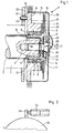
- a tachometer generator 7 The attachment of a tachometer generator 7 according to the invention on a continuous shaft is shown in Fig. 3.
- the drive shaft 2 of the drive motor 1 is offset from the continuous shaft 35 and thus forms the shaft collar 10.
- the rear end face 36 of the rotor 9 lies flush against this.
- the hollow shaft connection 6 of the rotor 9 is designed as a continuous cylindrical bore and is pushed over the hollow shaft 35 with a sliding seat.
- the design of the rotor 9 corresponds essentially to that described in the first example.
- the coding disk 19 is attached to it in the same way with a locking ring 18.
- the stator 14 has practically the same design as in the example described above and is mounted on the rotor 9 via the two ball bearings 12.
- the ball bearings 12 are secured on one side by a circlip 13 and on the other side by the bearing mounting ring 20 fastened to the stator 14 in the axial direction.
- the entire interior of the tachometer generator 7 is covered by a generator housing 25 which is fixedly connected to the stator 14.
- a cone clamping element 39 By means of a cone clamping element 39, the rotor 9 is pressed in the axial direction towards the shaft collar 10 of the drive shaft 2 via a stepped clamping ring 38 and the expandable spring washer 29.
- the cone clamping element 39 and the spring washer 29 form the quick release device 17.
- the cone clamping element 39 is in the axial direction towards the motor before being clamped continuous shaft 35 shifted until the stepped clamping ring 38 comes to rest on the front end face 41 of the rotor 9.
- the cone clamping element 39 is immovably clamped on the continuous shaft 35 by turning the clamping nut 40.
- the expandable spring washer 29 is now so tensioned that it exerts a sufficiently large force in the radial and axial direction to make the rear end face 36 of the rotor 9 flush with the shaft collar 10 of the drive shaft 2. This ensures that the encoder disk 9 carrying the encoder disk 19 is mounted on the drive shaft 2 without impact or twisting errors.
- the cone clamping element 39 used as part of the quick-action clamping device 17 is a component that can be obtained in free trade, for example from the company Ringspann Tollok.
- a U-shaped leaf spring 37 can be provided, which is firmly riveted to the motor housing 22 via an angled holding plate 42.
- the locking pin 21 fastened to the stator 14 is inserted into the U-shaped leaf spring 37 without play.
- Fig. 3 shows only an anti-rotation device. However, two can also be provided, for example.
- a continuous drive shaft 2 can be provided, into which a groove is inserted for receiving a fitting ring, which takes over the function of the shaft collar 10.
Landscapes
- Physics & Mathematics (AREA)
- General Physics & Mathematics (AREA)
- Connection Of Motors, Electrical Generators, Mechanical Devices, And The Like (AREA)
- Lubricants (AREA)
- Crystals, And After-Treatments Of Crystals (AREA)
- Inorganic Insulating Materials (AREA)
- Piezo-Electric Or Mechanical Vibrators, Or Delay Or Filter Circuits (AREA)
- Thermistors And Varistors (AREA)
- Golf Clubs (AREA)
- Transmission And Conversion Of Sensor Element Output (AREA)
- Oscillators With Electromechanical Resonators (AREA)
- Steroid Compounds (AREA)
Priority Applications (1)
| Application Number | Priority Date | Filing Date | Title |
|---|---|---|---|
| AT86116100T ATE67605T1 (de) | 1985-12-18 | 1986-11-20 | Befestigung eines tachogenerators an einer antriebswelle. |
Applications Claiming Priority (2)
| Application Number | Priority Date | Filing Date | Title |
|---|---|---|---|
| DE3544751 | 1985-12-18 | ||
| DE19853544751 DE3544751A1 (de) | 1985-12-18 | 1985-12-18 | Tachogenerator |
Publications (3)
| Publication Number | Publication Date |
|---|---|
| EP0226828A2 true EP0226828A2 (fr) | 1987-07-01 |
| EP0226828A3 EP0226828A3 (en) | 1989-07-19 |
| EP0226828B1 EP0226828B1 (fr) | 1991-09-18 |
Family
ID=6288743
Family Applications (1)
| Application Number | Title | Priority Date | Filing Date |
|---|---|---|---|
| EP86116100A Expired - Lifetime EP0226828B1 (fr) | 1985-12-18 | 1986-11-20 | Fixation d'un générateur tachymétrique à un arbre de commande |
Country Status (9)
| Country | Link |
|---|---|
| US (1) | US4759218A (fr) |
| EP (1) | EP0226828B1 (fr) |
| JP (2) | JPS62162966A (fr) |
| CN (1) | CN1004105B (fr) |
| AT (1) | ATE67605T1 (fr) |
| CA (1) | CA1289381C (fr) |
| DE (2) | DE3544751A1 (fr) |
| DK (1) | DK166973B1 (fr) |
| NO (1) | NO167829C (fr) |
Cited By (2)
| Publication number | Priority date | Publication date | Assignee | Title |
|---|---|---|---|---|
| DE3942826A1 (de) * | 1989-12-23 | 1991-06-27 | T & R Electronic Gmbh | Gehaeuseaufhaengung fuer ein messgeraet fuer drehbewegungen |
| US5550467A (en) * | 1992-04-29 | 1996-08-27 | Itt Automotive Europe Gmbh | Sensor including a follower for engaging the rotating portion of a bearing and having a sliding layer applied to the housing and encoder ring |
Families Citing this family (19)
| Publication number | Priority date | Publication date | Assignee | Title |
|---|---|---|---|---|
| DE3717180A1 (de) * | 1987-05-22 | 1988-12-08 | Licentia Gmbh | Elektromotor mit angebautem tachogenerator |
| DE3908932A1 (de) * | 1988-05-25 | 1989-12-07 | Heidenhain Gmbh Dr Johannes | Winkelmessvorrichtung |
| US5495758A (en) * | 1993-06-17 | 1996-03-05 | Lake Shore Cryotronics, Inc. | Tachometer assembly with integral internal wrench |
| DE4322744C2 (de) † | 1993-07-08 | 1998-08-27 | Baumueller Nuernberg Gmbh | Elektrisches Antriebssystem und Positionierverfahren zur synchronen Verstellung mehrerer dreh- und/oder verschwenkbarer Funktionsteile in Geräten und Maschinen, Antriebsanordnung mit einem Winkellagegeber und Druckmaschine |
| DE4324622A1 (de) * | 1993-07-22 | 1995-01-26 | Teves Gmbh Alfred | Vorrichtung zum Erfassen einer Drehbewegung |
| DE9315994U1 (de) * | 1993-10-20 | 1994-02-24 | Stroeter Antriebstech Gmbh | Flanschmotor mit Meßeinrichtung zur Erfassung der Umdrehung der Motorwelle |
| US5981940A (en) | 1997-09-15 | 1999-11-09 | Renco Encoders, Inc. | Angle measuring system with a clampable shaft |
| US6642508B2 (en) * | 2001-08-31 | 2003-11-04 | Renco Encoders, Inc. | System and method in an angle measuring system with an encoder attachment system for attaching an encoder to a motor shaft through the use of a spring generating a radial pressure |
| EP1340608B2 (fr) † | 2002-02-21 | 2011-04-20 | Reifenhäuser GmbH & Co. Maschinenfabrik | Appareil de lissage |
| US7109616B2 (en) * | 2003-10-16 | 2006-09-19 | Fasco Industries, Inc. | Electric motor with hall effect memory module |
| DE102005014808B4 (de) * | 2005-03-31 | 2009-11-26 | Siemens Ag | Messeinrichtung |
| DE202005006379U1 (de) * | 2005-04-21 | 2006-08-24 | Hengstler Gmbh | Hohlwellen-Drehgeber mit Motorwellen-Schutzkappe |
| US7932716B2 (en) | 2005-11-12 | 2011-04-26 | Valeo Schalter Und Sensoren Gmbh | Rotation angle sensor and rotation angle sensor system |
| DE102005060519A1 (de) * | 2005-12-11 | 2007-06-14 | Valeo Schalter Und Sensoren Gmbh | Drehwinkelsensor und Drehwinkelsensorsystem |
| DE102010035773A1 (de) * | 2010-08-26 | 2012-03-01 | Dunkermotoren Gmbh | Elektromotor und Verfahren zu dessen Herstellung |
| DE102010062480A1 (de) * | 2010-12-06 | 2012-06-06 | Aktiebolaget Skf | Wälzlageranordnung mit einem Drehgeber |
| CN103276525B (zh) * | 2013-06-08 | 2015-03-04 | 福建睿能科技股份有限公司 | 电脑横机及其码盘组件 |
| CN106841653A (zh) * | 2017-03-29 | 2017-06-13 | 湖南湘依铁路机车电器股份有限公司 | 一种机车转速信号轴端输出方法及装置 |
| DE102017117759A1 (de) * | 2017-08-04 | 2019-02-07 | Mimatic Gmbh | Sensornachrüstsatz |
Citations (3)
| Publication number | Priority date | Publication date | Assignee | Title |
|---|---|---|---|---|
| DE1221058B (de) * | 1961-09-14 | 1966-07-14 | Oskar E Peter | Befestigung einer Nabe auf einem Wellenende oder Wellenabsatz |
| US3995156A (en) * | 1975-03-25 | 1976-11-30 | Quick-Rotan Becker & Notz Kg | Transmitter for governed-speed drives employing an optical grating and photocells at an angle thereto |
| DE3038005A1 (de) * | 1980-10-08 | 1982-05-06 | Zinser Textilmaschinen Gmbh, 7333 Ebersbach | Elektrische maschine mit einem tachogenerator |
Family Cites Families (16)
| Publication number | Priority date | Publication date | Assignee | Title |
|---|---|---|---|---|
| US1320259A (en) * | 1919-10-28 | Ebanz mabtens | ||
| FR616315A (fr) * | 1925-05-19 | 1927-01-31 | élément élastique à bagues | |
| DE1016966B (de) * | 1956-01-11 | 1957-10-03 | Max Wuppermann Dipl Ing | Befestigung fuer Drehzahlmessgeraet od. dgl. |
| US3012744A (en) * | 1957-07-18 | 1961-12-12 | Waters Mfg Inc | Mounting device |
| DE1106854B (de) * | 1960-03-16 | 1961-05-18 | Licentia Gmbh | Elektrischer Hilfs-Stromerzeuger |
| DE6604776U (de) * | 1961-10-28 | 1970-02-26 | Johannes Huebner Fabrik Elek S | Gleich- oder wechselstrom-tachometerdynamo. |
| NL11261C (fr) * | 1965-05-04 | |||
| US3687184A (en) * | 1969-12-30 | 1972-08-29 | Illinois Tool Works | Fastener unit |
| US3693024A (en) * | 1971-05-17 | 1972-09-19 | Litton Systems Inc | Rotational shaft encoder having a bearing tube having a slot therein |
| DE2416113C2 (de) * | 1974-04-03 | 1984-09-27 | Quick-Rotan Becker & Notz Kg, 6100 Darmstadt | Istwertgeber für drehzahlgeregelte Antriebe |
| US4193199A (en) * | 1978-05-15 | 1980-03-18 | Servo Products Company | Shaft position transducer |
| JPS60513B2 (ja) * | 1978-06-16 | 1985-01-08 | 株式会社塚田工業 | 段葺金属屋根 |
| DE2921103C2 (de) * | 1979-05-25 | 1986-09-25 | Robert Bosch Gmbh, 7000 Stuttgart | Inkrementaler Drehwinkelgeber |
| DE3017193A1 (de) * | 1980-05-05 | 1981-11-12 | Siemens AG, 1000 Berlin und 8000 München | Einbauarmatur fuer messwertaufnehmer an schwer zugaenglich messstellen in maschinen |
| IT1129862B (it) * | 1980-11-17 | 1986-06-11 | Olivetti & Co Spa | Trasduttore ottico |
| DE3301205C2 (de) * | 1982-02-26 | 1985-10-03 | Dr. Johannes Heidenhain Gmbh, 8225 Traunreut | Winkelmeßeinrichtung |
-
1985
- 1985-12-18 DE DE19853544751 patent/DE3544751A1/de active Granted
-
1986
- 1986-11-06 CA CA000522395A patent/CA1289381C/fr not_active Expired - Lifetime
- 1986-11-19 DK DK553286A patent/DK166973B1/da not_active IP Right Cessation
- 1986-11-20 AT AT86116100T patent/ATE67605T1/de not_active IP Right Cessation
- 1986-11-20 DE DE8686116100T patent/DE3681568D1/de not_active Expired - Lifetime
- 1986-11-20 EP EP86116100A patent/EP0226828B1/fr not_active Expired - Lifetime
- 1986-12-17 NO NO865119A patent/NO167829C/no unknown
- 1986-12-17 CN CN86108532.9A patent/CN1004105B/zh not_active Expired
- 1986-12-18 JP JP61300205A patent/JPS62162966A/ja active Pending
- 1986-12-18 US US06/943,925 patent/US4759218A/en not_active Expired - Fee Related
-
1995
- 1995-01-10 JP JP000036U patent/JPH0743686U/ja active Pending
Patent Citations (3)
| Publication number | Priority date | Publication date | Assignee | Title |
|---|---|---|---|---|
| DE1221058B (de) * | 1961-09-14 | 1966-07-14 | Oskar E Peter | Befestigung einer Nabe auf einem Wellenende oder Wellenabsatz |
| US3995156A (en) * | 1975-03-25 | 1976-11-30 | Quick-Rotan Becker & Notz Kg | Transmitter for governed-speed drives employing an optical grating and photocells at an angle thereto |
| DE3038005A1 (de) * | 1980-10-08 | 1982-05-06 | Zinser Textilmaschinen Gmbh, 7333 Ebersbach | Elektrische maschine mit einem tachogenerator |
Cited By (2)
| Publication number | Priority date | Publication date | Assignee | Title |
|---|---|---|---|---|
| DE3942826A1 (de) * | 1989-12-23 | 1991-06-27 | T & R Electronic Gmbh | Gehaeuseaufhaengung fuer ein messgeraet fuer drehbewegungen |
| US5550467A (en) * | 1992-04-29 | 1996-08-27 | Itt Automotive Europe Gmbh | Sensor including a follower for engaging the rotating portion of a bearing and having a sliding layer applied to the housing and encoder ring |
Also Published As
| Publication number | Publication date |
|---|---|
| CN86108532A (zh) | 1987-08-26 |
| DE3681568D1 (de) | 1991-10-24 |
| EP0226828A3 (en) | 1989-07-19 |
| DE3544751A1 (de) | 1987-06-19 |
| NO167829C (no) | 1991-12-11 |
| DK553286A (da) | 1987-06-19 |
| NO865119L (no) | 1987-06-19 |
| JPS62162966A (ja) | 1987-07-18 |
| NO167829B (no) | 1991-09-02 |
| ATE67605T1 (de) | 1991-10-15 |
| DE3544751C2 (fr) | 1991-07-18 |
| EP0226828B1 (fr) | 1991-09-18 |
| US4759218A (en) | 1988-07-26 |
| DK553286D0 (da) | 1986-11-19 |
| JPH0743686U (ja) | 1995-09-05 |
| CA1289381C (fr) | 1991-09-24 |
| CN1004105B (zh) | 1989-05-03 |
| DK166973B1 (da) | 1993-08-09 |
| NO865119D0 (no) | 1986-12-17 |
Similar Documents
| Publication | Publication Date | Title |
|---|---|---|
| EP0226828B1 (fr) | Fixation d'un générateur tachymétrique à un arbre de commande | |
| EP1960753B1 (fr) | Dispositif de maintien pour jante de roue de vehicule | |
| EP0054774A2 (fr) | Mandrin de serrage | |
| DE3610284A1 (de) | Antriebsmechanismus mit einer gewindespindel und spindelmutter | |
| EP1752741B1 (fr) | Encodeur | |
| EP2805078B1 (fr) | Accouplement d'arbre et moyeu, adaptateur et moteur d'entrainement | |
| EP2826579A1 (fr) | Réceptacle de scie cloche et assemblage d'outil | |
| EP2445675B1 (fr) | Outil électrique à main | |
| DE19730198A1 (de) | Wellenkupplung | |
| DE3643255C2 (de) | Drehsignalgeber | |
| EP1514646A1 (fr) | Appareil pour la pose de rivets-écrous borgnes | |
| EP1758702B1 (fr) | Fixation de support d'outil | |
| EP0306830A2 (fr) | Machine pour mesurer les coordonnées | |
| WO2004039569A1 (fr) | Dispositif de presse electrique | |
| EP1328735B1 (fr) | Dispositif de fixation | |
| DE102010035551B4 (de) | Werkzeug für einen Roboter sowie Verfahren zum Herstellen einer Schraubverbindung | |
| DE102019121755A1 (de) | Mehrteiliges Stellelement | |
| DE102011088258A1 (de) | Getriebe zum Bewegen zweier Fahrzeugteile relativ zueinander | |
| EP4144467A1 (fr) | Dispositif de serrage | |
| DE10238271A1 (de) | Verfahren und Vorrichtung zum zentrierten Spannen eines Kraftfahrzeugrades auf eine Hauptwelle einer Radauswuchtmaschine | |
| DE1204126C2 (de) | Motorisch angetriebene bohrmaschine, die sowohl fuer schlag- als auch fuer drehbohren verwendbar ist | |
| DE10343725B4 (de) | Drehgeber | |
| DE3737773C2 (de) | Schnecken/Schneckenrad-Fahrstuhlantrieb und Verfahren zum Zusammenbauen desselben | |
| EP2025959A2 (fr) | Elément de machines pour une liaison arbre-moyeu et procédé de fabrication d'une liaison arbre-moyeu | |
| DE102016209361B4 (de) | Tretlager für ein Fahrrad |
Legal Events
| Date | Code | Title | Description |
|---|---|---|---|
| PUAI | Public reference made under article 153(3) epc to a published international application that has entered the european phase |
Free format text: ORIGINAL CODE: 0009012 |
|
| 17P | Request for examination filed |
Effective date: 19861120 |
|
| AK | Designated contracting states |
Kind code of ref document: A2 Designated state(s): AT BE CH DE FR GB IT LI NL SE |
|
| PUAL | Search report despatched |
Free format text: ORIGINAL CODE: 0009013 |
|
| AK | Designated contracting states |
Kind code of ref document: A3 Designated state(s): AT BE CH DE FR GB IT LI NL SE |
|
| 17Q | First examination report despatched |
Effective date: 19900724 |
|
| GRAA | (expected) grant |
Free format text: ORIGINAL CODE: 0009210 |
|
| AK | Designated contracting states |
Kind code of ref document: B1 Designated state(s): AT BE CH DE FR GB IT LI NL SE |
|
| REF | Corresponds to: |
Ref document number: 67605 Country of ref document: AT Date of ref document: 19911015 Kind code of ref document: T |
|
| REF | Corresponds to: |
Ref document number: 3681568 Country of ref document: DE Date of ref document: 19911024 |
|
| ITF | It: translation for a ep patent filed |
Owner name: STUDIO JAUMANN |
|
| GBT | Gb: translation of ep patent filed (gb section 77(6)(a)/1977) | ||
| ET | Fr: translation filed | ||
| PLBE | No opposition filed within time limit |
Free format text: ORIGINAL CODE: 0009261 |
|
| STAA | Information on the status of an ep patent application or granted ep patent |
Free format text: STATUS: NO OPPOSITION FILED WITHIN TIME LIMIT |
|
| 26N | No opposition filed | ||
| PGFP | Annual fee paid to national office [announced via postgrant information from national office to epo] |
Ref country code: BE Payment date: 19921110 Year of fee payment: 7 |
|
| PGFP | Annual fee paid to national office [announced via postgrant information from national office to epo] |
Ref country code: SE Payment date: 19921112 Year of fee payment: 7 |
|
| PGFP | Annual fee paid to national office [announced via postgrant information from national office to epo] |
Ref country code: NL Payment date: 19921130 Year of fee payment: 7 |
|
| PG25 | Lapsed in a contracting state [announced via postgrant information from national office to epo] |
Ref country code: SE Effective date: 19931121 |
|
| PG25 | Lapsed in a contracting state [announced via postgrant information from national office to epo] |
Ref country code: BE Effective date: 19931130 |
|
| BERE | Be: lapsed |
Owner name: HEIDELBERGER DRUCKMASCHINEN A.G. Effective date: 19931130 |
|
| PG25 | Lapsed in a contracting state [announced via postgrant information from national office to epo] |
Ref country code: NL Effective date: 19940601 |
|
| NLV4 | Nl: lapsed or anulled due to non-payment of the annual fee | ||
| EUG | Se: european patent has lapsed |
Ref document number: 86116100.8 Effective date: 19940610 |
|
| PGFP | Annual fee paid to national office [announced via postgrant information from national office to epo] |
Ref country code: GB Payment date: 19951018 Year of fee payment: 10 |
|
| PGFP | Annual fee paid to national office [announced via postgrant information from national office to epo] |
Ref country code: FR Payment date: 19951107 Year of fee payment: 10 |
|
| PGFP | Annual fee paid to national office [announced via postgrant information from national office to epo] |
Ref country code: AT Payment date: 19951114 Year of fee payment: 10 |
|
| PGFP | Annual fee paid to national office [announced via postgrant information from national office to epo] |
Ref country code: DE Payment date: 19951215 Year of fee payment: 10 |
|
| PGFP | Annual fee paid to national office [announced via postgrant information from national office to epo] |
Ref country code: CH Payment date: 19951222 Year of fee payment: 10 |
|
| PG25 | Lapsed in a contracting state [announced via postgrant information from national office to epo] |
Ref country code: GB Effective date: 19961120 Ref country code: AT Effective date: 19961120 |
|
| PG25 | Lapsed in a contracting state [announced via postgrant information from national office to epo] |
Ref country code: LI Effective date: 19961130 Ref country code: CH Effective date: 19961130 |
|
| GBPC | Gb: european patent ceased through non-payment of renewal fee |
Effective date: 19961120 |
|
| REG | Reference to a national code |
Ref country code: CH Ref legal event code: PL |
|
| PG25 | Lapsed in a contracting state [announced via postgrant information from national office to epo] |
Ref country code: FR Effective date: 19970731 |
|
| PG25 | Lapsed in a contracting state [announced via postgrant information from national office to epo] |
Ref country code: DE Effective date: 19970801 |
|
| REG | Reference to a national code |
Ref country code: FR Ref legal event code: ST |
|
| PG25 | Lapsed in a contracting state [announced via postgrant information from national office to epo] |
Ref country code: IT Free format text: LAPSE BECAUSE OF NON-PAYMENT OF DUE FEES Effective date: 20051120 |