EP0226828A2 - Mounting for a tacho-generator on a drive-shaft - Google Patents
Mounting for a tacho-generator on a drive-shaft Download PDFInfo
- Publication number
- EP0226828A2 EP0226828A2 EP86116100A EP86116100A EP0226828A2 EP 0226828 A2 EP0226828 A2 EP 0226828A2 EP 86116100 A EP86116100 A EP 86116100A EP 86116100 A EP86116100 A EP 86116100A EP 0226828 A2 EP0226828 A2 EP 0226828A2
- Authority
- EP
- European Patent Office
- Prior art keywords
- shaft
- tachometer generator
- rotor
- generator according
- drive shaft
- Prior art date
- Legal status (The legal status is an assumption and is not a legal conclusion. Google has not performed a legal analysis and makes no representation as to the accuracy of the status listed.)
- Granted
Links
Images

Classifications
-
- G—PHYSICS
- G01—MEASURING; TESTING
- G01P—MEASURING LINEAR OR ANGULAR SPEED, ACCELERATION, DECELERATION, OR SHOCK; INDICATING PRESENCE, ABSENCE, OR DIRECTION, OF MOVEMENT
- G01P1/00—Details of instruments
- G01P1/04—Special adaptations of driving means
Definitions
- the invention relates to a tachometer generator according to the preamble of claim 1.
- the drives e.g. Motors have different shaft diameters depending on their moments to be transmitted.
- the diameters of the drive shafts for commercially available generators, which applies to generators with solid shaft as well as generators with hollow shaft drive.
- the attachment of tachogenerators to the drive shafts is problematic, on the one hand because the different diameters of the drive shaft to the shaft connection of the tachogenerator, and on the other hand because shaft misalignment, concentricity errors and unbalance between the shaft or the hollow shaft connection of the tachogenerator and the drive shaft compensate Need to become.
- the object of the invention is to create a clutch-free attachment of a tachometer generator to a drive shaft with little installation depth, which is kept structurally simple and allows quick assembly and disassembly of the tachometer generator with little effort.
- the laying of the hollow shaft connection in the bore of the tachometer generator and its direct mounting on the drive shaft result in an operationally reliable and maintenance-free arrangement that eliminates any backlash and maintains an extremely short design of the drive.
- the use of the quick-action clamping device according to the invention not only has advantages in terms of production, but also time during assembly compared to conventional devices, and the centric axial clamping of the tachogenerator on the drive shaft guarantees absolute concentricity, which ensures accurate incremental measurement.
- a drive shaft 2 protruding from a drive motor 1 is provided with a cylindrically stepped shaft end 3, into which an internal thread 4 is introduced centrally, which has a large countersink 5 on the front side of the drive shaft 1.
- a tachometer generator 7 is arranged on the shaft end 3 by means of a hollow shaft connection 6.
- the rotor 9 is fitted by means of the transition fit (sliding fit) onto the stepped shaft end 3, with the rear end face 36 abutting against the shaft collar 10.
- the rotor 9 On the side facing the drive motor 2, the rotor 9 is equipped with a stepped bearing seat 11 on which ball bearings 12 are arranged.
- one of the ball bearings 12 is supported on a circlip 13 embedded in the bearing seat 11 in front of the shaft collar 10.
- a stator 14 which serves as a holder for a photoelectronic scanning unit, which consists of a transmitter 15 and a receiver 16, between which a coding disk 19 fixed to the rotor 9 by means of a locking ring 18 rotates.
- stator 14 The structural connection between the stator 14 and the rotor 9 is established via a bearing mounting ring 20 which is fastened to the stator 14 on its side facing the coding disk 19 and thereby covers one of the two ball bearings 12 laterally.
- a locking pin 21 is embedded in the stator 14, which projects into a bore 23 provided on the housing 22 of the drive motor 2 and thereby secures the stator 14 together with the photoelectric scanning device attached thereto against rotation in the circumferential direction.
- a dowel pin is preferably used as the locking pin 21 and the bore 23 is designed to compensate for tolerances with an elastic lining, for example in the form of a rubber sleeve 24. It may also be expedient to design the bore 23 as a radial elongated hole.
- the stator 14 is also attached to a generator housing 25 which surrounds the entire generator structure and which is provided centrally with a screw opening 26.
- the screw opening 26 can be used with a cover cap 27, preferably made of rubber or plastic, which is secured against falling out by means of an elastic cover cap holder 28 pivotably articulated on the generator housing 25, for example in the form of a spring shoe.
- a two-part quick release device 17 which consists of a spring washer 29, the spring force of which is directed against the end face of the drive shaft 1, and a quick release screw 30 projecting through it.
- a commercially available screw is expediently used as the quick-action screw 30, which is inserted through the screw opening 26 of the generator housing 25 and is received by the internal thread 4 of the drive shaft 1, which is usually already present and cannot be produced separately.
- the spring washer 29, a spacer sleeve 31 and a locking ring 32 are arranged one after the other.
- the spring washer 29 is designed as a concentric, expandable spring washer and is preferably positively attached to a shoulder within the stepped bore 8 of the rotor 9, e.g. by point-wise flanging the bore shoulder onto the spring washer 29, by spot welding, riveting, etc.
- the spacer sleeve 31 has one of the respective conditions, i.e. the length of the stepped shaft end 3 of the drive shaft 1 and the width and bore 8 of the tachometer generator 7 exactly matched length and is also provided with a bore 33, the inner diameter of which is slightly smaller than the outer diameter of the downstream circlip 32.
- a circlip 32 a commercially available O -Ring or preferably a steel ring may be used instead.
- the quick-action clamping device 17 is already assembled by the manufacturer according to the customer's specifications with the tachometer generator 7 to form a structural unit that can only be detached using a tool.
- the locking ring 32 in conjunction with the positive fastening of the spring washer 29 in the rotor 9 prevents the quick release device 17 from being separated from the tachometer generator 7. It is of course equally possible for the user himself to fasten the spring washer 29 in the rotor 9 and to insert the quick release screw 30 , the precisely adapted spacer sleeve 31 is placed on this and ultimately the retaining ring 32 is inserted into the threaded shaft of the clamping screw 30.
- the cover cap holder 28 is pivoted and the closure cap 27 is removed from the screw opening 26.
- the tachometer generator 7 is now placed on the cylindrical shaft end 3 of the drive shaft 1 in such a way that the locking pin 21 faces the bore 23 in the motor housing 22.
- the quick-release screw 30 is successively tightened by means of an ordinary wrench, whereby the rotor 9 with its hollow shaft connection 6 is pushed onto the cylindrically stepped shaft end 3 until it rests against the shaft collar 10 with the rear end face 36 and the locking pin 21 into the bore 23 intervenes.
- the tachometer generator 7 is disassembled by reversing the only required operation by simply loosening the quick-release screw 30. As soon as the locking ring 32 comes into contact with the spacer sleeve 31 after a few turns of the quick-release screw 30, it acts as a pulling device for the tachometer generator 7 from the drive shaft 1 Unscrewing the quick-action clamping screw 29 presses the spacer sleeve 31 against the spring washer 30 which is positively fastened in the rotor 9 and thereby causes the tachometer generator 7 to be released and pulled off from the cylindrically stepped shaft end 3.
- the stator 14 can also be secured against rotation with a differently designed resilient connection, namely the locking pins 21 fixed on the stator 14 meet compression spring elements 34 fastened to the motor housing 22.
- the compression spring elements 34 have the same spring characteristic. Their spring force acts in the direction of the respective locking pin 21, one compression spring element 34 is in and the other against the direction of rotation of the drive shaft 2 on the associated locking pin 21. It is advantageous if the two compression spring elements 34 are under slight pretension when the shaft is at a standstill.
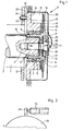
- a tachometer generator 7 The attachment of a tachometer generator 7 according to the invention on a continuous shaft is shown in Fig. 3.
- the drive shaft 2 of the drive motor 1 is offset from the continuous shaft 35 and thus forms the shaft collar 10.
- the rear end face 36 of the rotor 9 lies flush against this.
- the hollow shaft connection 6 of the rotor 9 is designed as a continuous cylindrical bore and is pushed over the hollow shaft 35 with a sliding seat.
- the design of the rotor 9 corresponds essentially to that described in the first example.
- the coding disk 19 is attached to it in the same way with a locking ring 18.
- the stator 14 has practically the same design as in the example described above and is mounted on the rotor 9 via the two ball bearings 12.
- the ball bearings 12 are secured on one side by a circlip 13 and on the other side by the bearing mounting ring 20 fastened to the stator 14 in the axial direction.
- the entire interior of the tachometer generator 7 is covered by a generator housing 25 which is fixedly connected to the stator 14.
- a cone clamping element 39 By means of a cone clamping element 39, the rotor 9 is pressed in the axial direction towards the shaft collar 10 of the drive shaft 2 via a stepped clamping ring 38 and the expandable spring washer 29.
- the cone clamping element 39 and the spring washer 29 form the quick release device 17.
- the cone clamping element 39 is in the axial direction towards the motor before being clamped continuous shaft 35 shifted until the stepped clamping ring 38 comes to rest on the front end face 41 of the rotor 9.
- the cone clamping element 39 is immovably clamped on the continuous shaft 35 by turning the clamping nut 40.
- the expandable spring washer 29 is now so tensioned that it exerts a sufficiently large force in the radial and axial direction to make the rear end face 36 of the rotor 9 flush with the shaft collar 10 of the drive shaft 2. This ensures that the encoder disk 9 carrying the encoder disk 19 is mounted on the drive shaft 2 without impact or twisting errors.
- the cone clamping element 39 used as part of the quick-action clamping device 17 is a component that can be obtained in free trade, for example from the company Ringspann Tollok.
- a U-shaped leaf spring 37 can be provided, which is firmly riveted to the motor housing 22 via an angled holding plate 42.
- the locking pin 21 fastened to the stator 14 is inserted into the U-shaped leaf spring 37 without play.
- Fig. 3 shows only an anti-rotation device. However, two can also be provided, for example.
- a continuous drive shaft 2 can be provided, into which a groove is inserted for receiving a fitting ring, which takes over the function of the shaft collar 10.
Abstract
Description
Die Erfindung betrifft einen Tachogenerator nach dem Oberbegriff des Anspruchs 1.The invention relates to a tachometer generator according to the preamble of
Es ist bekannt, Drehgeber an rotierenden Wellen anzubringen, um deren Rotationsbewegung in ein elektrisches Signal umzuwandeln, das eine Größe für die Drehgeschwindigkeit und deren Richtung darstellt. Als Drehgeber können dabei, je nach Bedarf und Anwendungsfall, Generatoren verwendet werden, die ausgangsseitig analoge Signale (Gleich- oder Wechselspannung) liefern oder Inkrementalgeber, welche digitale Informationen erzeugen.It is known to mount rotary encoders on rotating shafts in order to convert their rotational movement into an electrical signal which represents a variable for the speed of rotation and its direction. Depending on the need and application, generators can be used as rotary encoders that supply analog signals (direct or alternating voltage) on the output side or incremental encoders that generate digital information.
Die Antriebe, z.B. Motoren, weisen abhängig von ihren zu übertragenden Momenten unterschiedliche Wellendurchmesser auf. Ebenso besteht bei handelsüblichen Generatoren keine einheitliche Normung bezüglich der Durchmesser der Antriebswellen, was sowohl für Generatoren mit Vollwellen- als auch für Generatoren mit Hohlwellenantrieb zutrifft. Aus diesem Grunde ist die Befestigung von Tachogeneratoren an den Antriebswellen problematisch, zum einen deshalb, weil die unterschiedlichen Durchmesser von Antriebswelle zum Wellenanschluß des Tachogenerators, zum anderen, weil Wellenversatz, Rundlauffehler und Unwuchten zwischen der Welle bzw. dem Hohlwellenanschluß des Tachogenerators und der Antriebswelle ausgeglichen werden müssen.The drives, e.g. Motors have different shaft diameters depending on their moments to be transmitted. Likewise, there is no uniform standardization regarding the diameters of the drive shafts for commercially available generators, which applies to generators with solid shaft as well as generators with hollow shaft drive. For this reason, the attachment of tachogenerators to the drive shafts is problematic, on the one hand because the different diameters of the drive shaft to the shaft connection of the tachogenerator, and on the other hand because shaft misalignment, concentricity errors and unbalance between the shaft or the hollow shaft connection of the tachogenerator and the drive shaft compensate Need to become.
Aus diesem Grunde werden teils starre, teils elastische Zwischehkupplungen verwendet, die zwischen Antriebswelle und Tachogenerator eingebaut werden, wodurch jedoch eine unerwünschte Verlängerung der Antriebswelle und somit der Motorgesamtlänge bewirkt wird. Abgesehen davon, daß der hierzu erforderliche Platzbedarf oft nicht vorhanden ist, wirft die Montage und Demontage des Tachogenerators bei begrenzter Einbautiefe Probleme auf und ist somit sehr aufwendig und zeitraubend. Im übrigen bedarf der Einbau einer derartigen Zwischenkupplung größter Sorgfalt, da - insbesondere bei deren unsachgemäßer Montage - eine hohe Störanfälligkeit gegeben ist.For this reason, partly rigid, partly elastic intermediate couplings are used, which are installed between the drive shaft and tachometer generator, but this causes an undesirable extension of the drive shaft and thus the overall length of the motor. Apart from the fact that the the space required for this is often not available, the assembly and disassembly of the tacho generator with limited installation depth poses problems and is therefore very complex and time-consuming. Incidentally, the installation of such an intermediate coupling requires the greatest care, since - particularly when improperly installed - there is a high susceptibility to failure.
Infolge des großen Umkehrspiels haben elastische Zwischenkupplungen nur einen begrenzten Anwendungsbereich und sind für den Einsatz im Reversierbetrieb, z.B. beim Antrieb von Druckmaschinen, ungeeignet. Insbesondere bei digital messenden Inkrementalgebern ist jegliches Umkehrspiel unerwünscht und beeinflußt fehlerhaft deren Meßergebnis.Due to the large backlash, flexible intermediate couplings have only a limited area of application and are suitable for use in reverse operation, e.g. when driving printing machines, unsuitable. In particular with digitally measuring incremental encoders, any backlash is undesirable and incorrectly influences their measurement result.
Die Verwendung derartiger Zwischenkupplungen wird überflüssig bei Tachogeneratoren, die bereits mit einem Hohlwellenanschluß in Form eines am Rotor zusätzlich befestigten Klemmringes zur direkten Anordnung des Tachogenerators auf der Antriebswelle ausgestattet sind. Nachteilig wirkt sich hierbei aus, daß der Klemmring über das Gehäuse des Tachogenerators hinausragt und somit dessen Aufbau unnötig vergrößert und daß beim Anziehen der durch den Klemmring hindurchragenden Klemmschraube der Tachogenerator zumindest leicht exzentrisch auf der Antriebswelle verspannt wird. Diese leicht exzentrische Anordnung verursacht Rundlauffehler bzw. sogenannte "Höhenschläge" der am Rotor befestigten Kodierscheibe, was insbesondere bei einer feinkodierten Skala mit mehreren Tausend Skalenteilen zu fehlerhaften Meßergebnissen führen kann. Da die Skalenteile als Kreissektoren ausgebildet sind, verändert sich infolge der "Höhenschläge" durch die leicht exzentrische Rotation der Kodierscheibe die jeweils von der Leseoptik wahrgenommene Breite eines Skalenteils, so daß dadurch teilweise zu viele bzw. teilweise zu wenig Inkremente gemessen werden. Demgemäß besteht die Aufgabe der Erfindung darin, mit geringem Aufwand eine kupplungslose Befestigung eines Tachogenerators an einer Antriebswelle unter Wahrung geringer Einbautiefe zu schaffen, die konstruktiv einfach gehalten ist und eine schnelle Montage bzw. Demontage des Tachogenerators ermöglicht.The use of such intermediate couplings becomes superfluous in tachogenerators which are already equipped with a hollow shaft connection in the form of a clamping ring additionally attached to the rotor for direct arrangement of the tachogenerator on the drive shaft. The disadvantage here is that the clamping ring protrudes beyond the housing of the tachometer generator and thus unnecessarily enlarges its structure and that when the clamping screw protruding through the clamping ring is tightened, the tachometer generator is at least slightly eccentrically clamped on the drive shaft. This slightly eccentric arrangement causes radial runout or so-called "heights" of the encoder disk attached to the rotor, which can lead to erroneous measurement results, particularly in the case of a finely coded scale with several thousand scale parts. Since the scale parts are designed as circular sectors, the "height swings" due to the slightly eccentric rotation of the coding disk change the width of a scale part perceived by the reading optics, so that sometimes too many or sometimes too few increments are measured. Accordingly, the object of the invention is to create a clutch-free attachment of a tachometer generator to a drive shaft with little installation depth, which is kept structurally simple and allows quick assembly and disassembly of the tachometer generator with little effort.
Diese Aufgabe wird in allgemeiner Form gemäß dem Kennzeichen des Anspruchs 1 gelöst.This object is achieved in general form according to the characterizing part of
Durch die Verlegung des Hohlwellenanschlusses in die Bohrung des Tachogenerators und dessen direkte Lagerung auf der Antriebswelle ergibt sich eine betriebssichere und wartungsfreie Anordnung, durch die jegliches Umkehrspiel ausgeschlossen und eine äußerst kurze Bauform des Antriebes eingehalten wird. Die Verwendung der erfindungsgemäßen Schnellspanneinrichtung hat nicht nur herstellungsmäßige, sondern auch zeitliche Vorteile bei der Montage gegenüber herkömmlichen Einrichtungen und die zentrische axiale Festklemmung des Tachogenerators an der Antriebswelle garantiert eine absolute Konzentrizität, wodurch eine genaue Inkrementalmessung gewährleistet ist.The laying of the hollow shaft connection in the bore of the tachometer generator and its direct mounting on the drive shaft result in an operationally reliable and maintenance-free arrangement that eliminates any backlash and maintains an extremely short design of the drive. The use of the quick-action clamping device according to the invention not only has advantages in terms of production, but also time during assembly compared to conventional devices, and the centric axial clamping of the tachogenerator on the drive shaft guarantees absolute concentricity, which ensures accurate incremental measurement.
In Weiterbildung des Erfindungsgedankens ergeben sich besonders vorteilhafte Ausgestaltungen aus den Unteransprüchen in Verbindung mit der zugehörigen Beschreibung und der Zeichnung.In a further development of the inventive concept, particularly advantageous embodiments result from the subclaims in conjunction with the associated description and the drawing.
Die mit Vorrichtungen nach den Unteransprüchen 2 und 3 erzielten Vorteile bestehen neben einer kostengünstigen Herstellung insbesondere darin, daß die Montage bzw. Demontage des Tachogenerators infolge Einfachheit mittels nur eines einzigen Werkzeuges, z.B. eines Steck- oder Innensechskantschlüssels, durchgeführt werden und dabei kein Bauteil vergessen oder verloren gehen kann.The advantages achieved with devices according to
Die Weiterbildung des Erfindungsgedankens gemäß dem Kennzeichen des Unteranspruches 5 ermöglicht in vorteilhafter Weise, daß sich der Tachogenerator selbst nach langjährigem Einsatz in kürzester Zeit noch leicht ohne Spezialwerkzeug, wie z.B. eine Abziehvorrichtung, von der Antriebswelle demontieren läßt, da keine komplizierten Arbeitsgänge in Art und Reihenfolge einzuhalten sind, sondern nur ein einziger Arbeitsgang, das Lösen der Sicherungsschraube, anfällt.The development of the inventive concept according to the characterizing part of
Die Erfindung wird im folgenden anhand eines in der Zeichnung dargestellten Ausführungsbeispieles näher erläutert.The invention is explained below with reference to an embodiment shown in the drawing.
Es zeigt:
- Fig. 1 eine geschnittene Darstellung . eines an einer Antriebswelle mittels Schnellspanneinrichtung befestigten Tachogenerators,
- Fig. 2 eine elastische Verdrehsicherung für den Tachogenerator nach der Erfindung,
- Fig. 3 eine Anbringungsmöglichkeit eines Tachogenerators nach der Erfindung auf einer durchgehenden Welle und
- Fig. 4 eine weitere elastische Verdrehsicherung des Tachogenerators.
- Fig. 1 is a sectional view. a tachometer generator attached to a drive shaft by means of a quick release device,
- 2 is an elastic anti-rotation device for the tachometer generator according to the invention,
- Fig. 3 shows a possibility of mounting a tachometer generator according to the invention on a continuous shaft and
- Fig. 4 shows another elastic anti-rotation device of the tachometer generator.
Eine aus einem Antriebsmotor 1 herausragende Antriebswelle 2 ist mit einem zylindrisch abgesetzten Wellenende 3 versehen, in das zentrisch ein Innengewinde 4 eingebracht ist, das an der Stirnseite der Antriebswelle 1 eine starke Ansenkung 5 aufweist. Auf dem Wellenende 3 ist mittels eines Hohlwellenanschlusses 6 ein Tachogenerator 7 angeordnet.A
Der vorzugsweise mit einer Übergangspassung versehene Hohlwellenanschluß 6 ist Teil einer abgestuften Bohrung 8, die sich durch einen als Drehteil ausgebildeten Rotor 9 erstreckt. Der Rotor 9 ist mittels der Übergangspassung (Schiebesitz) auf das abgesetzte Wellenende 3, mit der hinteren Stirnfläche 36 gegen den Wellenbund 10 anstoßend, aufgesteckt. Auf der dem Antriebsmotor 2 zugewandten Seite ist der Rotor 9 mit einem abgesetzten Lagersitz 11 ausgestattet, auf dem Kugellager 12 angeordnet sind. Zur Motorseite hin stützt sich eines der Kugellager 12 an einem im Lagersitz 11 vor dem Wellenbund 10 eingelassenen Seegering 13 ab.The
Auf den Kugellagern 12 ist ein Stator 14 angeordnet, der als Halterung für eine photoelektronische Abtasteinheit dient, die aus einem Sender 15 sowie einem Empfänger 16 besteht, zwischen denen eine am Rotor 9 mittels eines Feststellringes 18 fixierte Kodierscheibe 19 umläuft.Arranged on the
Die bauliche Verbindung zwischen dem Stator 14 und dem Rotor 9 wird über einen Lagerbefestigungsring 20 hergestellt, der an dem Stator 14 auf seiner der Kodierscheibe 19 zugewandten Seite befestigt ist und dabei seitlich einen der beiden Kugellager 12 überdeckt. In dem Stator 14 ist ein Arretierstift 21 eingelassen, der in eine am Gehäuse 22 des Antriebsmotors 2 vorgesehene Bohrung 23 hineinragt und dadurch den Stator 14 nebst daran befestigter photoelektrischer Abtasteinrichtung gegen Verdrehen in Umfangsrichtung sichert. Vorzugsweise wird als Arretierstift 21 ein Paßstift verwendet und die Bohrung 23 zum Kompensieren von Toleranzen mit einer elastischen Auskleidung, beispielsweise in Form einer Gummimuffe 24, ausgelegt. Auch kann es zweckmäßig sein, die Bohrung 23 als radiales Langloch auszuführen.The structural connection between the
Ar: dem Stator 14 ist außerdem ein den gesamten Generatoraufbau umschließendes Generatorgehäuse 25 befestigt, das zentrisch mit einer Schraubenöffnung 26 versehen ist. In die Schraubenöffnung 26 ist zwecks Verhinderung des Eindringens von Staub und Verunreinigungen eine Abdeckkappe 27, vorzugsweise aus Gummi oder Kunststoff, einsetzbar, die mittels eines am Generatorgehäuse 25 verschwenkbar angelenkten, elastischen Abdeckkappenhalters 28, z.B. in Form eines Federschuhs, gegen Herausfallen gesichert ist.Ar: The
Im Zentrum des Tachogenerators 7 ist eine zweiteilige Schnellspanneinrichtung 17 angeordnet, welche aus einer Federscheibe 29, dessen Federkraft gegen die Stirnseite der Antriebswelle 1 gerichtet ist, sowie einer durch diese hindurchragenden Schnellspannschraube 30 besteht. Als Schnellspannschraube 30 wird zweckmäßigerweise eine handelsübliche Schraube verwendet, die durch die Schraubenöffnung 26 des Generatorgehäuses 25 eingeführt und ' von dem ohnehin zumeist vorhandenen und nicht extra zu fertigenden Innengewinde 4 der Antriebswelle 1 aufgenommen wird. Auf der Spannschraube 30 sind, von deren Schraubenkopf her gesehen, nacheinander die Federscheibe 29, eine Distanzhülse 31 sowie ein Sicherungsring 32 angeordnet. Die Federscheibe 29 ist als konzentrische, spreizbare Federscheibe ausgebildet und vorzugsweise an einem Absatz innerhalb der abgestuften Bohrung 8 des Rotors 9 formschlüssig befestigt, z.B. durch punktweises Umbördeln des Bohrungsabsatzes auf die Federscheibe 29, durch Punktschweißen, Vernieten usw. Die Distanzbüchse 31 hat eine den jeweiligen Verhältnissen, d.h. der Länge des abgesetzten Wellenendes 3 der Antriebswelle 1 sowie der Baubreite und Bohrung 8 des Tachogenerators 7 genau angepaßte Länge und ist außerdem mit einer Bohrung 33 versehen, deren Innendurchmesser geringfügig kleiner ist als der Außendurchmesser des nachgeordneten Sicherungsringes 32. Als Sicherungsring 32 kann ein handelsüblicher O-Ring oder stattdessen vorzugsweise ein Stahlring verwendet werden.In the center of the tachometer generator 7 there is a two-part
Zweckmäßigerweise wird die Schnellspanneinrichtung 17 bereits beim Hersteller gemäß den Kundenangaben mit dem Tachogenerator 7 zu einer nur mittels Werkzeug zu lösenden Baueinheit zusammengesetzt. In diesem Fall verhindert der Sicherungsring 32 in Verbindung mit der formschlüssigen Befestigung der Federscheibe 29 im Rotor 9 eine Trennung der Schnellspanneinrichtung 17 vom Tachogenerator 7. Es ist natürlich ebensogut möglich, daß der Anwender selbst die Federscheibe 29 im Rotor 9 befestigt, die Schnellspannschraube 30 hindurchsteckt, auf diese die genau angepaßte Distanzhülse 31 aufsetzt und letztendlich den Sicherungsring 32 in den Gewindeschaft der Spannschraube 30 einläßt.Expediently, the quick-
Vor der eigentlichen Montage des Tachogenerators 7 wird der Abdeckkappenhalter 28 verschwenkt und die Verschlußkappe 27 von der Schraubenöffnung 26 entfernt. Der Tachogenerator 7 wird nun auf das zylindrisch abgesetzte Wellenende 3 der Antriebswelle 1 derart aufgesetzt, daß der Arretierstift 21 der Bohrung 23 im Motorgehäuse 22 gegenübersteht. Danach wird die Schnellspannschraube 30 mittels eines gewöhnlichen Schraubenschlüssels sukzessive angezogen, wodurch sich der Rotor 9 mit seinem Hohlwellenanschluß 6 auf das zylindrisch abgesetzte Wellenende 3 aufschiebt, bis er sich mit der hinteren Stirnfläche 36 gegen den Wellenbund 10 anlegt und der Arretierstift 21 in die Bohrung 23 eingreift.Before the actual installation of the tachometer generator 7, the
Im angezogenen Zustand der Schnellspannschraube 30 kommt der Sicherungsring 32 im Bereich der Ansenkung 5 des Innengewindes 4 der Antriebswelle 1 zu liegen und der Antrieb des Rotors 9 ist nicht nur reibschlüssig, sondern durch die Befestigung der Federscheibe 29 im Rotor 9 auch formschlüssig sichergestellt. Ein Überdrehen der Federscheibe 29 infolge zu großen Anzugsmomentes der Schnellspannschraube 30 ist praktisch unmöglich, da die Länge der Distanzhülse 31 so bemessen ist, daß sich die Federscheibe 29 nicht plastisch verformen kann und dadurch der für die Aufrechterhaltung des Reibschlusses erforderliche Federdruck in Richtung gegen die Antriebswelle 1 stets aufrechterhalten bleibt, unabhängig vom Anzugsmoment der Schnellspannschraube 30.In the tightened state of the quick-
Die Demontage des Tachogenerators 7 erfolgt durch Umkehrung des einzig erforderlichen Arbeitsganges durch einfaches Lösen der Schnellspannschraube 30. Sobald der Sicherungsring 32 nach einigen Umdrehungen der Schnellspannschraube 30 an die Distanzhülse 31 stößt, wirkt er als Abziehvorrichtung für den Tachogenerator 7 von der Antriebswelle 1. Beim weiteren Herausschrauben der Schnellspannschraube 29 drückt die Distanzhülse 31 gegen die formschlüssig im Rotor 9 befestigte Federscheibe 30 und bewirkt dadurch ein Lösen und Abziehen des Tachogenerators 7 vom zylindrisch abgesetzten Wellenende 3.The tachometer generator 7 is disassembled by reversing the only required operation by simply loosening the quick-
Da sowohl bei der Montage als auch bei der Demontage nur ein einziger Arbeitsgang erforderlich ist, der infolge Einfachheit das Auftreten von Fehlern ausschließt, können diese Arbeiten von ungeschultem Hilfspersonal, zumindest unter Beaufsichtigung, durchgeführt werden. Durch die paßgenaue konzentrische Anordnung des Tachogenerators 7 und dessen absolut zentrische Festklemmung an der Antriebswelle 1 treten Rundlauffehler so gut wie gar nicht auf. Sollten dennoch geringfügige Toleranzen, egal ob in axialer oder radialer Richtung, vorhanden sein, so werden diese durch die Gummimuffe 24 der Bohrung 23 im Motorgehäuse 22 aufgenommen und kompensiert. Die Möglichkeit des Festklemmens des Tachogenerators 7 an der Antriebswelle 1 mit großem Anzugsmoment in Verbindung mit der Ausbildung des Arretierstiftes 21 als Paßstift mit zugehöriger Paßbohrung 23 im Motorgehäuse 22 hält das Umkehrspiel in derart geringen Grenzen, daß es die inkrementale Wegmessung, auch bei feinkodierter Impulsscheibe, nicht mehr feststellbar beeinflußt.Since both assembly and disassembly require only one work step, which, due to simplicity, prevents errors from occurring, this work can be carried out by untrained auxiliary staff, at least under supervision. Due to the precisely fitting concentric arrangement of the tachometer generator 7 and its absolutely centric clamping on the
Wie aus Fig. 2 zu ersehen, kann die Verdrehsicherung des Stators 14 auch mit einer anders gestalteten federnden Verbindung erfolgen, und zwar treffen die am Stator 14 fixierten Arretierstifte 21 auf am Motorgehäuse 22 befestigte Druckfederelemente 34. Die Druckfederelemente 34 weisen eine gleiche Federkennlinie auf. Ihre Federkraft wirkt in Richtung des jeweils anstoßenden Arretierstifts 21, dabei liegt das eine Druckfederelement 34 in und das andere entgegen der Drehrichtung der Antriebswelle 2 am zugeordneten Arretierstift 21 an. Vorteilhaft ist, wenn die beiden Druckfederelemente 34 bei Wellenstillstand unter geringer Vorspannung stehen.As can be seen from FIG. 2, the
Die Anbringung eines Tachogenerators 7 nach der Erfindung auf einer durchgehenden Welle ist in Fig. 3 dargestellt. Die Antriebswelle 2 des Antriebsmotors 1 ist zu der durchgehenden Welle 35 abgesetzt und bildet somit den Wellenbund 10. Hieran liegt die hintere Stirnfläche 36 des Rotors 9 bündig an. Der Hohlwellenanschluß 6 des Rotors 9 ist im Gegensatz zu der Ausführungsform nach Fig. l als durchgehend zylindrische Bohrung ausgeführt und mit einem Schiebesitz über die Hohlwelle 35 geschoben. Die Ausbildung des Rotors 9 entspricht im wesentlichen der in dem ersten Beispiel beschriebenen. Auf ihm ist die Kodierscheibe 19 in derselben Weise mit einem Feststellring 18 angebracht. Der Stator 14 hat praktisch die gleiche Ausbildung wie in dem zuvor beschriebenen Beispiel und ist über die beiden Kugellager 12 auf dem Rotor 9 gelagert. Auch in diesem Fall sind die Kugellager 12 an der einen Seite durch einen Seegering 13 und an der anderen Seite durch den am Stator 14 befestigten Lagerbefestigungsring 20 in axialer Richtung gesichert. Das ganze Innere des Tachogenerators 7 deckt ein mit dem Stator 14 fest verbundenes Generatorgehäuse 25 ab. Mittels eines Konus-Spannelementes 39 wird der Rotor 9 in axialer Richtung zum Wellenbund 10 der Antriebswelle 2 hin über einen abgestuften Spannring 38 und die spreizbare Federscheibe 29 gedrückt. Das Konus-Spannelement 39 und die Federscheibe 29 bilden die Schnellspannvorrichtung 17. Damit die hintere Stirnfläche 36. des Rotors 9 mit Sicherheit plan an dem Wellenbund 10 anliegt, wird das Konus-Spannelement 39 vor dem Verklemmen solange in axialer Richtung zum Motor hin auf der durchgehenden Welle 35 verschoben, bis der abgestufte Spannring 38 an der vorderen Stirnfläche 41 des Rotors 9 zur Anlage kommt. Sobald dies geschehen ist, wird mittels Drehen der Spannmutter 40 das Konus-Spannelement 39 auf der durchgehenden Welle 35 unverrückbar verklemmt. Die spreizbare Federscheibe 29 ist nun derartig gespannt, daß sie in radialer und axialer Richtung eine genügend große Kraft ausübt, um die hintere Stirnfläche 36 des Rotors 9 bündig an den Wellenbund 10 der Antriebswelle 2 anzulegen. Damit ist eine schlag- und verdrehfehlerfreie Anbringung des Kodierscheibe 19 tragenden Rotors 9 auf der Antriebswelle 2 gewährleistet.The attachment of a tachometer generator 7 according to the invention on a continuous shaft is shown in Fig. 3. The
Das als Teil der Schnellspannvorrichtung 17 eingesetzte Konus-Spannelement 39 ist ein im freien Handel beziehbares Bauteil, beispielsweise bei der Firma Ringspann Tollok.The
Zwecks Verdrehsicherung des Stators 14 kann, wie in Fig. 4 gezeigt, eine U-förmig gebogene Blattfeder 37 vorgesehen sein, die über eine abgewinkelte Halteplatte 42 am Motorgehäuse 22 fest vernietet ist. In die U-förmige Blattfeder 37 ist der am Stator 14 befestigte Arretierstift 21 spielfrei eingeführt. Fig. 3 zeigt nur eine Verdrehsicherung. Es können aber beispielsweise auch zwei vorgesehen sein.To prevent the
Selbstverständlich ist die Erfindung nicht nur auf die in den Figuren dargestellten und in der Beschreibung niedergelegten Ausführungsformen beschränkt, die lediglich als ein die Erfindung nicht begrenzendes Beispiel anzusehen sind. Es versteht sich von selbst, daß vielfältige bauliche Ausgestaltungen und insbesondere die Verwendung äquivalenter mechanischer Bauteile im abgesteckten Rahmen der Erfindung liegen. Beispielsweise kann eine durchgehende Antriebswelle 2 vorgesehen sein, in die eine Nut eingestochen ist zur Aufnahme eines Paßrings, der die Aufgabe des Wellenbundes 10 übernimmt.Of course, the invention is not only based on those shown in the figures and in the description limited embodiments, which are only to be regarded as an example not limiting the invention. It goes without saying that a wide range of structural designs and in particular the use of equivalent mechanical components are within the scope of the invention. For example, a
- 1 Antriebsmotor1 drive motor
- 2 Antriebswelle2 drive shaft
- 3 Wellenende3 shaft end
- 4 Innengewinde4 internal threads
- 5 Ansenkung5 countersink
- 6 Hohlwellenanschluß6 hollow shaft connection
- 7 Tachogenerator7 tachometer generator
- 8 Bohrung8 hole
- 9 Rotor9 rotor
- 10 Wellenbund10 shaft collar
- 11 Lagersitz11 bearing seat
- 12 Kugellager12 ball bearings
- 13 Seegering13 Seegering
- 14 Stator14 stator
- 15 Sender15 transmitters
- 16 Empfänger16 receivers
- 17 Schnellspannvorrichtung17 quick release device
- 18 Feststellring18 locking ring
- 19 Kodierscheibe19 coding disk
- 20 Lagerbefestigungsring20 bearing mounting ring
- 21 Arretierstift21 locking pin
- 22 Motorgehäuse22 Motor housing
- 23 Bohrung23 hole
- 24 Gummimuffe24 rubber sleeve
- 25 Generatorgehäuse25 generator housing
- 26 Schraubenöffnung26 screw opening
- 27 Abdeckkappe27 cover cap
- 28 Abdeckkappenhalter28 cover cap holder
- 29 Federscheibe29 spring washer
- 30 Schnellspannschraube30 quick release screw
- 31 Distanzbüchse31 spacer
- 32 Sicherungsring32 circlip
- 33 Bohrung33 hole
- 34 Druckfederelement34 compression spring element
- 35 durchgehende Welle35 continuous wave
- 36 hintere Stirnfläche36 rear end face
- 37 U-förmige Blattfeder37 U-shaped leaf spring
- 38 Spannring38 tension ring
- 39 Konus-Spannelement39 cone clamping element
- 40 Spannmutter40 clamping nut
- 41 vordere Stirnfläche41 front face
- 42 Halteplatte42 holding plate
Claims (13)
dadurch gekennzeichnet ,
daß der Hohlwellenanschluß (6) Teil des Rotors (9) des Tachogenerators ist und auf der Antriebswelle (2) drehfest angebracht ist, daß der Stator (14) über Lager (12) auf dem Rotor (9), dem Träger der Kodierscheibe (19), frei drehbar gelagert ist und daß die hintere Stirnfläche (36) des Rotors (9) von dem Klemmelement plan gegen einen Wellenbund (10) der rotierenden Antriebswelle (2) angelegt ist.l. Tachometer generator in a short design with a hollow shaft connection and a clamping element for fixing on a rotating drive shaft, the stator of the tachometer generator being connected to a stationary machine part to prevent rotation.
characterized ,
that the hollow shaft connection (6) is part of the rotor (9) of the tachometer generator and is mounted on the drive shaft (2) in a rotationally fixed manner, that the stator (14) via bearings (12) on the rotor (9), the carrier of the coding disk (19 ), is freely rotatable and that the rear end face (36) of the rotor (9) of the clamping element is flat against a shaft collar (10) of the rotating drive shaft (2).
dadurch gekennzeichnet ,
daß zur reib- und/oder formschlüssigen Mitnahme des Rotors (9) auf der Antriebswelle (2) eine Schnellspannvorrichtung (17) mit einer verdrehgesicherten Federscheibe (29) mit axial gegen den Wellenbund (10) gerichteter Federkraft, sowie mit einem in axialer Richtung verschraubbaren, konzentrisch angeordneten Spannelement (30 bzw. 39) versehen ist.2. tachometer generator according to claim 1,
characterized ,
that for the frictional and / or positive entrainment of the rotor (9) on the drive shaft (2) a quick release device (17) with a non-rotating spring washer (29) with axially directed against the shaft collar (10) spring force, and with a screwable in the axial direction , concentrically arranged clamping element (30 or 39) is provided.
dadurch gekennzeichnet ,
daß zur Verdrehsicherung des Stators (14) zwischen diesem und dem feststehenden Motorgehäuse (22) zumindest zwei federnde, jedoch ausreichend drehwinkelstarre Verbindungen (21, 23, 24) in diametraler Anordnung vorgesehen sind.3. tachometer generator according to claim 1 or 2,
characterized ,
that to prevent rotation of the stator (14) between it and the fixed motor housing (22) at least two resilient but sufficiently angularly rigid connections (21, 23, 24) are provided in a diametrical arrangement.
dadurch gekennzeichnet ,
daß die federnden Verbindungen aus am Stator (14) fixierten Arretierstiften (21) und den am Motorgehäuse (22) befestigten Druckfederelementen (34) mit gegen die Arretierstifte (21) gerichteter Federkraft und gleicher Federkennlinie bestehen, wobei das eine Druckfederelement (34) in und das andere (34) entgegen der Drehrichtung der Antriebswelle (2) am jeweiligen Arretierstift (21) anliegt und die beiden Druckfederelemente (34) im Wellenstillstand vorzugsweise unter geringer Vorspannung stehen.4. tachometer generator according to claim 3,
characterized ,
that the resilient connections consist of locking pins (21) fixed on the stator (14) and the compression spring elements (34) attached to the motor housing (22) with spring force directed against the locking pins (21) and the same spring characteristic, the one compression spring element (34) in and the other (34) abuts against the respective locking pin (21) against the direction of rotation of the drive shaft (2) and the two compression spring elements (34) are preferably under slight prestress when the shaft is at a standstill.
dadurch gekennzeichnet ,
daß ein beim Anziehen des Spannelementes (30 bzw. 40) den Federweg der Federscheibe (29) begrenzendes und gleichzeitig dessen plastische Verformung verhinderndes Distanzelement (31 bzw. 38) vorgesehen ist.5. tachometer generator according to one or more of the preceding claims,
characterized ,
that when the tensioning element (30 or 40) is tightened, the spring travel of the spring washer (29) is limited and at the same time prevents its plastic deformation, spacer element (31 or 38) is provided.
dadurch gekennzeichnet ,
daß im Zentrum eines Generatorgehäuses (25) eine Schraubenöffnung (26) eingelassen ist, in die eine unverlierbar gesicherte Abdeckkappe (27) einsetzbar ist.6. tachometer generator according to one or more of the preceding claims,
characterized ,
that in the center of a generator housing (25) a screw opening (26) is inserted into which a captively secured cover cap (27) can be inserted.
dadurch gekennzeichnet ,
daß das Spannelement als zentrisch in das Wellenende (3) einschraubbare Spannschraube (30) ausgebildet ist.7. tachometer generator according to one or more of the preceding claims,
characterized ,
that the clamping element is designed as a clamping screw (30) which can be screwed centrally into the shaft end (3).
dadurch gekennzeichnet ,
daß das Spannelement als axial verschiebbares, auf der Welle durch Verdrehen einer Spannmutter (40) feststellbares Konus-Spannelement (39) ausgebildet ist. 8 . Tachometer generator according to one or more of the preceding claims,
characterized ,
that the clamping element is designed as an axially displaceable, conical clamping element (39) which can be fixed on the shaft by turning a clamping nut (40).
gekennzeichnet
durch eine derartige Ausbildung des Rotors (9), daß die Bearbeitung des Hohlwellenanschlusses (6), des Lagersitzes (11) und der Aufnahmezylinderfläche für die Kodierscheibe (19) zur Vermeidung von Rundlauffehlern aus einer Richtung möglich ist.9. tachometer generator according to one or more of the preceding claims,
featured
by designing the rotor (9) in such a way that the machining of the hollow shaft connection (6), the bearing seat (11) and the receiving cylinder surface for the coding disk (19) is possible in order to avoid radial run-out errors from one direction.
dadurch gekennzeichnet ,
daß mit Hilfe des Sicherungsringes (32) in Verbindung mit der Federscheibe (29) die Schnellspannschraube (30) unverlierbar gesichert ist.10. tachometer generator according to one or more of the preceding claims,
characterized ,
that with the aid of the locking ring (32) in connection with the spring washer (29) the quick-release screw (30) is captively secured.
dadurch gekennzeichnet ,
daß zur Verdrehsicherung des Stators (14) am Motorgehäuse (22) U-förmig gebogene Blattfedern (37) befestigt sind, in die am Stator angebrachte Arretierstifte (21) spielfrei hineinragen.11. tachometer generator according to one or more of the preceding claims,
characterized ,
that to prevent rotation of the stator (14) on the motor housing (22) U-shaped curved leaf springs (37) are attached, into which locking pins (21) attached to the stator project without play.
dadurch gekennzeichnet,
daß das Klemmelement als eine Schnellspannvorrichtung (17) ausgebildet ist, die auf den Rotor (9) sowohl eine radiale als auch eine in Richtung auf den Wellenbund (10) wirkende Spannkraft ausübt.12. tachometer generator according to claim 1,
characterized,
that the clamping element is designed as a quick-action clamping device (17) which exerts both a radial and a clamping force acting in the direction of the shaft collar (10) on the rotor (9).
dadurch gekennzeichnet ,
daß auf einer durchgehenden Antriebswelle 2 eine Nut eingestochen ist, in die ein Paßring eingesetzt ist, der einen dem Wellenbund (10) entsprechenden Anschlag bildet.13. Tacoh generator according to one or more of the preceding claims,
characterized ,
that on a continuous drive shaft 2 a groove is inserted into which a fitting ring is inserted, which forms a stop corresponding to the shaft collar (10).
Priority Applications (1)
| Application Number | Priority Date | Filing Date | Title |
|---|---|---|---|
| AT86116100T ATE67605T1 (en) | 1985-12-18 | 1986-11-20 | ATTACHING A TACHOGENERATOR TO A DRIVE SHAFT. |
Applications Claiming Priority (2)
| Application Number | Priority Date | Filing Date | Title |
|---|---|---|---|
| DE3544751 | 1985-12-18 | ||
| DE19853544751 DE3544751A1 (en) | 1985-12-18 | 1985-12-18 | TACHOGENERATOR |
Publications (3)
| Publication Number | Publication Date |
|---|---|
| EP0226828A2 true EP0226828A2 (en) | 1987-07-01 |
| EP0226828A3 EP0226828A3 (en) | 1989-07-19 |
| EP0226828B1 EP0226828B1 (en) | 1991-09-18 |
Family
ID=6288743
Family Applications (1)
| Application Number | Title | Priority Date | Filing Date |
|---|---|---|---|
| EP86116100A Expired - Lifetime EP0226828B1 (en) | 1985-12-18 | 1986-11-20 | Mounting for a tacho-generator on a drive-shaft |
Country Status (9)
| Country | Link |
|---|---|
| US (1) | US4759218A (en) |
| EP (1) | EP0226828B1 (en) |
| JP (2) | JPS62162966A (en) |
| CN (1) | CN1004105B (en) |
| AT (1) | ATE67605T1 (en) |
| CA (1) | CA1289381C (en) |
| DE (2) | DE3544751A1 (en) |
| DK (1) | DK166973B1 (en) |
| NO (1) | NO167829C (en) |
Cited By (2)
| Publication number | Priority date | Publication date | Assignee | Title |
|---|---|---|---|---|
| DE3942826A1 (en) * | 1989-12-23 | 1991-06-27 | T & R Electronic Gmbh | Rotation measurement device housing suspension - contains cross-linkage allowing radial motion of measurement shaft |
| US5550467A (en) * | 1992-04-29 | 1996-08-27 | Itt Automotive Europe Gmbh | Sensor including a follower for engaging the rotating portion of a bearing and having a sliding layer applied to the housing and encoder ring |
Families Citing this family (19)
| Publication number | Priority date | Publication date | Assignee | Title |
|---|---|---|---|---|
| DE3717180A1 (en) * | 1987-05-22 | 1988-12-08 | Licentia Gmbh | ELECTRIC MOTOR WITH ATTACHED TACHOGENERATOR |
| DE3908932A1 (en) * | 1988-05-25 | 1989-12-07 | Heidenhain Gmbh Dr Johannes | ANGLE MEASURING DEVICE |
| US5495758A (en) * | 1993-06-17 | 1996-03-05 | Lake Shore Cryotronics, Inc. | Tachometer assembly with integral internal wrench |
| DE4322744C2 (en) † | 1993-07-08 | 1998-08-27 | Baumueller Nuernberg Gmbh | Electrical drive system and positioning method for the synchronous adjustment of several rotatable and / or pivotable functional parts in devices and machines, drive arrangement with an angular position encoder and printing machine |
| DE4324622A1 (en) * | 1993-07-22 | 1995-01-26 | Teves Gmbh Alfred | Device for detecting the rotary movement |
| DE9315994U1 (en) * | 1993-10-20 | 1994-02-24 | Stroeter Antriebstech Gmbh | Flange motor with measuring device to record the rotation of the motor shaft |
| US5981940A (en) | 1997-09-15 | 1999-11-09 | Renco Encoders, Inc. | Angle measuring system with a clampable shaft |
| US6642508B2 (en) * | 2001-08-31 | 2003-11-04 | Renco Encoders, Inc. | System and method in an angle measuring system with an encoder attachment system for attaching an encoder to a motor shaft through the use of a spring generating a radial pressure |
| PT1340608E (en) † | 2002-02-21 | 2004-10-29 | Reifenhaeuser Masch | STREAMING DEVICE |
| US7109616B2 (en) * | 2003-10-16 | 2006-09-19 | Fasco Industries, Inc. | Electric motor with hall effect memory module |
| DE102005014808B4 (en) * | 2005-03-31 | 2009-11-26 | Siemens Ag | measuring device |
| DE202005006379U1 (en) * | 2005-04-21 | 2006-08-24 | Hengstler Gmbh | Hollow shaft encoder with motor shaft protection cap |
| DE102005060519A1 (en) * | 2005-12-11 | 2007-06-14 | Valeo Schalter Und Sensoren Gmbh | Rotation angle sensor for use in motor vehicle, has signal transducer which is arranged on shaft mount, housing fastened to shaft end by shaft mount, and signal receiver arranged on housing and interacting with transducer |
| US7932716B2 (en) | 2005-11-12 | 2011-04-26 | Valeo Schalter Und Sensoren Gmbh | Rotation angle sensor and rotation angle sensor system |
| DE102010035773A1 (en) * | 2010-08-26 | 2012-03-01 | Dunkermotoren Gmbh | Electric motor and method for its production |
| DE102010062480A1 (en) * | 2010-12-06 | 2012-06-06 | Aktiebolaget Skf | Rolling bearing assembly used in gearbox of engine, has rotary encoder and code transducer that are accommodated within transmitter housings comprising rotatably mounted coding unit coupled with shaft |
| CN103276525B (en) * | 2013-06-08 | 2015-03-04 | 福建睿能科技股份有限公司 | Computerized flat knitting machine and code disc assembly |
| CN106841653A (en) * | 2017-03-29 | 2017-06-13 | 湖南湘依铁路机车电器股份有限公司 | A kind of locomotive tach signal shaft end output intent and device |
| DE102017117759A1 (en) * | 2017-08-04 | 2019-02-07 | Mimatic Gmbh | Sensor retrofit kit |
Citations (3)
| Publication number | Priority date | Publication date | Assignee | Title |
|---|---|---|---|---|
| DE1221058B (en) * | 1961-09-14 | 1966-07-14 | Oskar E Peter | Attachment of a hub to a shaft end or shaft shoulder |
| US3995156A (en) * | 1975-03-25 | 1976-11-30 | Quick-Rotan Becker & Notz Kg | Transmitter for governed-speed drives employing an optical grating and photocells at an angle thereto |
| DE3038005A1 (en) * | 1980-10-08 | 1982-05-06 | Zinser Textilmaschinen Gmbh, 7333 Ebersbach | Rotating machine with built-in tachometer - eliminates unwanted axial and radial motion between stator and rotor |
Family Cites Families (16)
| Publication number | Priority date | Publication date | Assignee | Title |
|---|---|---|---|---|
| US1320259A (en) * | 1919-10-28 | Ebanz mabtens | ||
| FR616315A (en) * | 1925-05-19 | 1927-01-31 | elastic ring element | |
| DE1016966B (en) * | 1956-01-11 | 1957-10-03 | Max Wuppermann Dipl Ing | Attachment for tachometer or the like. |
| US3012744A (en) * | 1957-07-18 | 1961-12-12 | Waters Mfg Inc | Mounting device |
| DE1106854B (en) * | 1960-03-16 | 1961-05-18 | Licentia Gmbh | Auxiliary electrical generator |
| DE6604776U (en) * | 1961-10-28 | 1970-02-26 | Johannes Huebner Fabrik Elek S | DC OR AC TACHOMETER DYNAMO. |
| NL11261C (en) * | 1965-05-04 | |||
| US3687184A (en) * | 1969-12-30 | 1972-08-29 | Illinois Tool Works | Fastener unit |
| US3693024A (en) * | 1971-05-17 | 1972-09-19 | Litton Systems Inc | Rotational shaft encoder having a bearing tube having a slot therein |
| DE2416113C2 (en) * | 1974-04-03 | 1984-09-27 | Quick-Rotan Becker & Notz Kg, 6100 Darmstadt | Actual value encoder for speed-controlled drives |
| US4193199A (en) * | 1978-05-15 | 1980-03-18 | Servo Products Company | Shaft position transducer |
| JPS60513B2 (en) * | 1978-06-16 | 1985-01-08 | 株式会社塚田工業 | tiered metal roof |
| DE2921103C2 (en) * | 1979-05-25 | 1986-09-25 | Robert Bosch Gmbh, 7000 Stuttgart | Incremental rotary encoder |
| DE3017193A1 (en) * | 1980-05-05 | 1981-11-12 | Siemens AG, 1000 Berlin und 8000 München | BUILT-IN ARMATURE FOR MEASURING VALVES AT HARD ACCESSIBLE MEASURING POINTS IN MACHINES |
| IT1129862B (en) * | 1980-11-17 | 1986-06-11 | Olivetti & Co Spa | OPTICAL TRANSDUCER |
| DE3301205C2 (en) * | 1982-02-26 | 1985-10-03 | Dr. Johannes Heidenhain Gmbh, 8225 Traunreut | Angle measuring device |
-
1985
- 1985-12-18 DE DE19853544751 patent/DE3544751A1/en active Granted
-
1986
- 1986-11-06 CA CA000522395A patent/CA1289381C/en not_active Expired - Lifetime
- 1986-11-19 DK DK553286A patent/DK166973B1/en not_active IP Right Cessation
- 1986-11-20 DE DE8686116100T patent/DE3681568D1/en not_active Expired - Lifetime
- 1986-11-20 AT AT86116100T patent/ATE67605T1/en not_active IP Right Cessation
- 1986-11-20 EP EP86116100A patent/EP0226828B1/en not_active Expired - Lifetime
- 1986-12-17 NO NO865119A patent/NO167829C/en unknown
- 1986-12-17 CN CN86108532.9A patent/CN1004105B/en not_active Expired
- 1986-12-18 US US06/943,925 patent/US4759218A/en not_active Expired - Fee Related
- 1986-12-18 JP JP61300205A patent/JPS62162966A/en active Pending
-
1995
- 1995-01-10 JP JP000036U patent/JPH0743686U/en active Pending
Patent Citations (3)
| Publication number | Priority date | Publication date | Assignee | Title |
|---|---|---|---|---|
| DE1221058B (en) * | 1961-09-14 | 1966-07-14 | Oskar E Peter | Attachment of a hub to a shaft end or shaft shoulder |
| US3995156A (en) * | 1975-03-25 | 1976-11-30 | Quick-Rotan Becker & Notz Kg | Transmitter for governed-speed drives employing an optical grating and photocells at an angle thereto |
| DE3038005A1 (en) * | 1980-10-08 | 1982-05-06 | Zinser Textilmaschinen Gmbh, 7333 Ebersbach | Rotating machine with built-in tachometer - eliminates unwanted axial and radial motion between stator and rotor |
Cited By (2)
| Publication number | Priority date | Publication date | Assignee | Title |
|---|---|---|---|---|
| DE3942826A1 (en) * | 1989-12-23 | 1991-06-27 | T & R Electronic Gmbh | Rotation measurement device housing suspension - contains cross-linkage allowing radial motion of measurement shaft |
| US5550467A (en) * | 1992-04-29 | 1996-08-27 | Itt Automotive Europe Gmbh | Sensor including a follower for engaging the rotating portion of a bearing and having a sliding layer applied to the housing and encoder ring |
Also Published As
| Publication number | Publication date |
|---|---|
| CA1289381C (en) | 1991-09-24 |
| DK553286A (en) | 1987-06-19 |
| DE3681568D1 (en) | 1991-10-24 |
| NO167829C (en) | 1991-12-11 |
| JPS62162966A (en) | 1987-07-18 |
| NO865119L (en) | 1987-06-19 |
| CN86108532A (en) | 1987-08-26 |
| JPH0743686U (en) | 1995-09-05 |
| EP0226828A3 (en) | 1989-07-19 |
| DK166973B1 (en) | 1993-08-09 |
| US4759218A (en) | 1988-07-26 |
| ATE67605T1 (en) | 1991-10-15 |
| NO167829B (en) | 1991-09-02 |
| DK553286D0 (en) | 1986-11-19 |
| DE3544751A1 (en) | 1987-06-19 |
| NO865119D0 (en) | 1986-12-17 |
| EP0226828B1 (en) | 1991-09-18 |
| CN1004105B (en) | 1989-05-03 |
| DE3544751C2 (en) | 1991-07-18 |
Similar Documents
| Publication | Publication Date | Title |
|---|---|---|
| EP0226828B1 (en) | Mounting for a tacho-generator on a drive-shaft | |
| EP1960753B1 (en) | Maintaining device for a rim of a vehicle wheel | |
| EP0054774A2 (en) | Chuck | |
| DE3610284A1 (en) | DRIVE MECHANISM WITH A SCREW AND NUT | |
| EP1752741B1 (en) | Rotary encoder | |
| EP2805078B1 (en) | Shaft-hub coupling, adapter and drive motor | |
| EP2826579A1 (en) | Holding fixture for a hole saw and tool assembly | |
| DE19730198A1 (en) | Shaft coupling | |
| EP2445675B1 (en) | Hand-held elecrtical tool | |
| DE3643255C2 (en) | Rotary signal transmitter | |
| EP1514646A1 (en) | Blind rivet nut setting tool | |
| CH690119A5 (en) | Hand drill and the tool holder. | |
| EP1758702B1 (en) | Tool holding fixture | |
| EP0306830A2 (en) | Coordinate-measuring machine | |
| WO2004039569A1 (en) | Electrical pressing device | |
| EP1328735B1 (en) | Clamping mechanism | |
| DE102010035551B4 (en) | Tool for a robot and method for producing a screw connection | |
| DE102019121755A1 (en) | Multi-part actuator | |
| DE102011088258A1 (en) | Gear for moving two vehicle sections relative to each other, has gear wheel, which is rotatable around rotational axis and has toothing, where toothing of gear wheel is formed of multiple teeth | |
| DE10238271A1 (en) | Method and device for centering clamping of a motor vehicle wheel on a main shaft of a wheel balancing machine | |
| DE1204126C2 (en) | MOTOR-DRIVEN DRILLING MACHINE THAT CAN BE USED BOTH FOR IMPACT AND ROTARY DRILLING | |
| DE10343725B4 (en) | encoders | |
| DE3737773C2 (en) | Worm / worm wheel elevator drive and method for assembling the same | |
| EP2025959A2 (en) | Machine element for a shaft-to-hub connection and production method for a shaft-to-hub connection | |
| DE102016209361B4 (en) | Bottom bracket for a bicycle |
Legal Events
| Date | Code | Title | Description |
|---|---|---|---|
| PUAI | Public reference made under article 153(3) epc to a published international application that has entered the european phase |
Free format text: ORIGINAL CODE: 0009012 |
|
| 17P | Request for examination filed |
Effective date: 19861120 |
|
| AK | Designated contracting states |
Kind code of ref document: A2 Designated state(s): AT BE CH DE FR GB IT LI NL SE |
|
| PUAL | Search report despatched |
Free format text: ORIGINAL CODE: 0009013 |
|
| AK | Designated contracting states |
Kind code of ref document: A3 Designated state(s): AT BE CH DE FR GB IT LI NL SE |
|
| 17Q | First examination report despatched |
Effective date: 19900724 |
|
| GRAA | (expected) grant |
Free format text: ORIGINAL CODE: 0009210 |
|
| AK | Designated contracting states |
Kind code of ref document: B1 Designated state(s): AT BE CH DE FR GB IT LI NL SE |
|
| REF | Corresponds to: |
Ref document number: 67605 Country of ref document: AT Date of ref document: 19911015 Kind code of ref document: T |
|
| REF | Corresponds to: |
Ref document number: 3681568 Country of ref document: DE Date of ref document: 19911024 |
|
| ITF | It: translation for a ep patent filed |
Owner name: STUDIO JAUMANN |
|
| GBT | Gb: translation of ep patent filed (gb section 77(6)(a)/1977) | ||
| ET | Fr: translation filed | ||
| PLBE | No opposition filed within time limit |
Free format text: ORIGINAL CODE: 0009261 |
|
| STAA | Information on the status of an ep patent application or granted ep patent |
Free format text: STATUS: NO OPPOSITION FILED WITHIN TIME LIMIT |
|
| 26N | No opposition filed | ||
| PGFP | Annual fee paid to national office [announced via postgrant information from national office to epo] |
Ref country code: BE Payment date: 19921110 Year of fee payment: 7 |
|
| PGFP | Annual fee paid to national office [announced via postgrant information from national office to epo] |
Ref country code: SE Payment date: 19921112 Year of fee payment: 7 |
|
| PGFP | Annual fee paid to national office [announced via postgrant information from national office to epo] |
Ref country code: NL Payment date: 19921130 Year of fee payment: 7 |
|
| PG25 | Lapsed in a contracting state [announced via postgrant information from national office to epo] |
Ref country code: SE Effective date: 19931121 |
|
| PG25 | Lapsed in a contracting state [announced via postgrant information from national office to epo] |
Ref country code: BE Effective date: 19931130 |
|
| BERE | Be: lapsed |
Owner name: HEIDELBERGER DRUCKMASCHINEN A.G. Effective date: 19931130 |
|
| PG25 | Lapsed in a contracting state [announced via postgrant information from national office to epo] |
Ref country code: NL Effective date: 19940601 |
|
| NLV4 | Nl: lapsed or anulled due to non-payment of the annual fee | ||
| EUG | Se: european patent has lapsed |
Ref document number: 86116100.8 Effective date: 19940610 |
|
| PGFP | Annual fee paid to national office [announced via postgrant information from national office to epo] |
Ref country code: GB Payment date: 19951018 Year of fee payment: 10 |
|
| PGFP | Annual fee paid to national office [announced via postgrant information from national office to epo] |
Ref country code: FR Payment date: 19951107 Year of fee payment: 10 |
|
| PGFP | Annual fee paid to national office [announced via postgrant information from national office to epo] |
Ref country code: AT Payment date: 19951114 Year of fee payment: 10 |
|
| PGFP | Annual fee paid to national office [announced via postgrant information from national office to epo] |
Ref country code: DE Payment date: 19951215 Year of fee payment: 10 |
|
| PGFP | Annual fee paid to national office [announced via postgrant information from national office to epo] |
Ref country code: CH Payment date: 19951222 Year of fee payment: 10 |
|
| PG25 | Lapsed in a contracting state [announced via postgrant information from national office to epo] |
Ref country code: GB Effective date: 19961120 Ref country code: AT Effective date: 19961120 |
|
| PG25 | Lapsed in a contracting state [announced via postgrant information from national office to epo] |
Ref country code: LI Effective date: 19961130 Ref country code: CH Effective date: 19961130 |
|
| GBPC | Gb: european patent ceased through non-payment of renewal fee |
Effective date: 19961120 |
|
| REG | Reference to a national code |
Ref country code: CH Ref legal event code: PL |
|
| PG25 | Lapsed in a contracting state [announced via postgrant information from national office to epo] |
Ref country code: FR Effective date: 19970731 |
|
| PG25 | Lapsed in a contracting state [announced via postgrant information from national office to epo] |
Ref country code: DE Effective date: 19970801 |
|
| REG | Reference to a national code |
Ref country code: FR Ref legal event code: ST |
|
| PG25 | Lapsed in a contracting state [announced via postgrant information from national office to epo] |
Ref country code: IT Free format text: LAPSE BECAUSE OF NON-PAYMENT OF DUE FEES Effective date: 20051120 |