EP2805078B1 - Shaft-hub coupling, adapter and drive motor - Google Patents
Shaft-hub coupling, adapter and drive motor Download PDFInfo
- Publication number
- EP2805078B1 EP2805078B1 EP12810069.0A EP12810069A EP2805078B1 EP 2805078 B1 EP2805078 B1 EP 2805078B1 EP 12810069 A EP12810069 A EP 12810069A EP 2805078 B1 EP2805078 B1 EP 2805078B1
- Authority
- EP
- European Patent Office
- Prior art keywords
- shaft
- hub
- adapter
- clamping ring
- connection according
- Prior art date
- Legal status (The legal status is an assumption and is not a legal conclusion. Google has not performed a legal analysis and makes no representation as to the accuracy of the status listed.)
- Active
Links
- 230000008878 coupling Effects 0.000 title description 4
- 238000010168 coupling process Methods 0.000 title description 4
- 238000005859 coupling reaction Methods 0.000 title description 4
- 230000005540 biological transmission Effects 0.000 description 7
- 238000004519 manufacturing process Methods 0.000 description 4
- 238000003860 storage Methods 0.000 description 3
- 238000006243 chemical reaction Methods 0.000 description 2
- 238000003780 insertion Methods 0.000 description 2
- 230000037431 insertion Effects 0.000 description 2
- 241000755266 Kathetostoma giganteum Species 0.000 description 1
- 230000006735 deficit Effects 0.000 description 1
- 230000001066 destructive effect Effects 0.000 description 1
- 238000009826 distribution Methods 0.000 description 1
- 230000000694 effects Effects 0.000 description 1
- 230000005484 gravity Effects 0.000 description 1
- 239000010687 lubricating oil Substances 0.000 description 1
- 238000003754 machining Methods 0.000 description 1
- 238000007789 sealing Methods 0.000 description 1
- 238000009827 uniform distribution Methods 0.000 description 1
- 239000002023 wood Substances 0.000 description 1
Images


Classifications
-
- F—MECHANICAL ENGINEERING; LIGHTING; HEATING; WEAPONS; BLASTING
- F16—ENGINEERING ELEMENTS AND UNITS; GENERAL MEASURES FOR PRODUCING AND MAINTAINING EFFECTIVE FUNCTIONING OF MACHINES OR INSTALLATIONS; THERMAL INSULATION IN GENERAL
- F16D—COUPLINGS FOR TRANSMITTING ROTATION; CLUTCHES; BRAKES
- F16D1/00—Couplings for rigidly connecting two coaxial shafts or other movable machine elements
- F16D1/06—Couplings for rigidly connecting two coaxial shafts or other movable machine elements for attachment of a member on a shaft or on a shaft-end
- F16D1/08—Couplings for rigidly connecting two coaxial shafts or other movable machine elements for attachment of a member on a shaft or on a shaft-end with clamping hub; with hub and longitudinal key
- F16D1/09—Couplings for rigidly connecting two coaxial shafts or other movable machine elements for attachment of a member on a shaft or on a shaft-end with clamping hub; with hub and longitudinal key with radial clamping due to axial loading of at least one pair of conical surfaces
- F16D1/092—Couplings for rigidly connecting two coaxial shafts or other movable machine elements for attachment of a member on a shaft or on a shaft-end with clamping hub; with hub and longitudinal key with radial clamping due to axial loading of at least one pair of conical surfaces the pair of conical mating surfaces being provided on the coupled hub and shaft
-
- F—MECHANICAL ENGINEERING; LIGHTING; HEATING; WEAPONS; BLASTING
- F16—ENGINEERING ELEMENTS AND UNITS; GENERAL MEASURES FOR PRODUCING AND MAINTAINING EFFECTIVE FUNCTIONING OF MACHINES OR INSTALLATIONS; THERMAL INSULATION IN GENERAL
- F16D—COUPLINGS FOR TRANSMITTING ROTATION; CLUTCHES; BRAKES
- F16D1/00—Couplings for rigidly connecting two coaxial shafts or other movable machine elements
- F16D1/06—Couplings for rigidly connecting two coaxial shafts or other movable machine elements for attachment of a member on a shaft or on a shaft-end
- F16D1/08—Couplings for rigidly connecting two coaxial shafts or other movable machine elements for attachment of a member on a shaft or on a shaft-end with clamping hub; with hub and longitudinal key
- F16D1/0847—Couplings for rigidly connecting two coaxial shafts or other movable machine elements for attachment of a member on a shaft or on a shaft-end with clamping hub; with hub and longitudinal key with radial clamping due to a radial screw
Description
Die Erfindung betrifft eine Welle-Nabe-Verbindung, einen Adapter und einen Getriebemotor.The invention relates to a shaft-hub connection, an adapter and a geared motor.
Es sind Adapter für Getriebemotoren bekannt, die eine Kupplung umfassen, mit welcher eine Motorwelle eintriebsseitig und eine eintreibende Welle eines Getriebes abtriebsseitig verbindbar sind.There are known adapters for geared motors which comprise a coupling with which a motor shaft on the input side and an input shaft of a gearbox on the output side can be connected.
Aus der
Aus der
Aus der
Aus der
Aus der
Aus der
Der Erfindung liegt daher die Aufgabe zugrunde, eine Klemm-Verbindung in einfach herstellbarer Weise weiterzubilden.The invention is therefore the object of developing a clamping connection in a simple manner producible.
Erfindungsgemäß wird die Aufgabe bei der Welle-Nabe-Verbindung nach den in Anspruch 1, bei dem Adapter nach den in Anspruch 14 und bei dem Getriebemotor nach den in Anspruch 15 angegebenen Merkmalen gelöst.According to the invention the object is achieved in the shaft-hub connection according to the in
Wichtige Merkmale der Erfindung bei der Welle-Nabe-Verbindung sind, dass bei der Welle-Nabe-Verbindung eine Welle, insbesondere Motorwelle, in einen Aufnahmebereich einer Nabe, insbesondere Adapterwelle, eingeführt und kraftschlüssig verbunden ist, insbesondere klemmverbunden ist,
wobei die Nabe zumindest in einem axialen Bereich drei, in Umfangsrichtung regelmäßig voneinander beabstandete Abflachungen aufweist,
wobei ein erstes Schraubteil, insbesondere ein erster vorzugsweise radial wirkender Gewindestift, in einen Klemmring eingeschraubt ist und auf einen Bereich der Nabe drückt zur Bewirkung der kraftschlüssigen Verbindung, insbesondere mittels Verspannen des Klemmrings gegen die Nabe, wobei der Bereich in Umfangsrichtung mittig zwischen zwei der Abflachungen angeordnet ist, insbesondere wobei der Bereich einen Umfangswinkelbereich überdeckt, weicher kleiner ist als der Winkelabstand in Umfangsrichtung zwischen zwei in Umfangsrichtung nächst benachbarten Abflachungen.Important features of the invention in the shaft-hub connection are that in the shaft-hub connection, a shaft, in particular motor shaft, in a receiving area of a hub, in particular adapter shaft, inserted and positively connected, in particular is clamped,
wherein the hub has at least in an axial region three, circumferentially regularly spaced flats,
wherein a first screw, in particular a first preferably radially acting threaded pin, is screwed into a clamping ring and presses on a region of the hub to effect the frictional connection, in particular by means of clamping the clamping ring against the hub, wherein the region in the circumferential direction centrally between two of the flats is arranged, in particular wherein the region covers a circumferential angle range, which is smaller than the angular distance in the circumferential direction between two circumferentially adjacent adjacent flats.
Von Vorteil ist dabei, dass ein einfache und schnell betätigbare Verbindung erreicht ist. Außerdem ist ein zentrisch spannendes Klemmsystem in einfacher Weise herstellbar. Die zentrische Klemmung der Welle in der Nabe wird durch die symmetrische Anordnung der Abflachungen erreichbar.The advantage here is that a simple and quickly operable connection is reached. In addition, a centrically exciting clamping system can be produced in a simple manner. The centric clamping of the shaft in the hub is achieved by the symmetrical arrangement of the flats.
Vorteiligerweise ist die Welle-Nabe-Vorrichtung über die Welle lagerbar. Diese Welle ist beispielsweise in einem Motorgehäuse lagerbar über zwei Lager. Hierbei ist das von der Welle-Nabe-Verbindung abgewandte Lager als axiales Festlager ausführbar und das zur Welle-Nabe-Verbindung näher zugewandte Lager als axiales Loslager. Somit ist auf dem von der Welle-Nabe-Verbindung abgewandten Ende der Welle ein Winkelsensoren oder dergleichen anordenbar. Thermisch bedingte Längenveränderungen verschieben somit das andere axiale Ende der Welle und somit auch die Welle-Nabe-Verbindung. Da diese aber über die Lagerung der Welle gelagert ist, besteht keine Beeinträchtigung durch thermisch bedingte Längenveränderungen der Welle. Insbesondere bei Ausführung der Nabe mit Sonnenverzahnung oder bei Verbindung der Nabe mit einer Sonnenradwelle verschiebt sich die Sonnenradverzahnung thermisch bedingt nur axial, wobei die Planetenradverzahnung und Sonnenradverzahnung mit zumindest teilweise axial sich erstreckenden Verzahnungen versehen sind.Advantageously, the shaft-hub device is storable over the shaft. This shaft can be stored for example in a motor housing via two bearings. Here, the bearing facing away from the shaft-hub connection bearing is designed as an axial bearing and the closer to the shaft-hub connection facing bearing as an axial floating bearing. Thus, on the side facing away from the shaft-hub connection end of the shaft, an angle sensors or the like can be arranged. Thermally induced changes in length thus shift the other axial end of the shaft and thus also the shaft-hub connection. But since this is mounted on the bearing of the shaft, there is no impairment due to thermally induced changes in length of the shaft. In particular, in the design of the hub with sun teeth or when connecting the hub with a sun gear, the sun gear shifts thermally only axially, the planetary gear and sun gear are provided with at least partially axially extending teeth.
Weiter ist von Vorteil, dass geschlitzte Buchsen und dergleichen verzichtbar sind. Die Erfindung kommt also mit äußerst kostengünstigen Bauteilen aus.It is also advantageous that slotted bushes and the like are dispensable. The invention thus comes with extremely inexpensive components.
Bei einer vorteilhaften Ausgestaltung sind die Abflachungen auf der von der Welle abgewandten Außenseite der Nabe angeordnet. Von Vorteil ist dabei, dass eine einfache Herstellung der Nabe ausführbar ist. Außerdem sind somit die Bereiche dickerer Wandstärke gleichmäßig am Umfang verteilt.In an advantageous embodiment, the flats are arranged on the side facing away from the shaft outside of the hub. The advantage here is that a simple production of the hub is executable. In addition, the areas thicker wall thickness are thus distributed evenly around the circumference.
Bei einer vorteilhaften Ausgestaltung ist der Klemmring mit der Nabe drehfest verbunden, insbesondere wobei die Abflachungen zwischen dem Klemmring und der Nabe angeordnet sind. Von Vorteil ist dabei, dass beim Einführen der Welle, also zeitlich vor dem Klemmverbinden, die Welle zentrisch in die Nabe einführbar ist und beim Klemmverbinden dann durch die drei Bereiche dickerer Wandstärke die Welle zentrisch fixierbar ist.In an advantageous embodiment of the clamping ring is rotatably connected to the hub, in particular wherein the flats between the clamping ring and the hub are arranged. The advantage here is that during insertion of the shaft, ie, before the clamping connection, the shaft is centrally inserted into the hub and the clamping connection then through the three areas thicker wall thickness, the shaft is centrally fixed.
Der Bereich ist in Umfangsrichtung mittig zwischen zwei der Abflachungen angeordnet, insbesondere liegt der Bereich vom von den Abflachungen axial überdeckten Bereich.The region is arranged centrally between two of the flats in the circumferential direction, in particular the region of the region axially covered by the flattened areas.
Von Vorteil ist dabei, dass dort eine höhere Wandstärke realisierbar ist und außerdem eine zentrische Aufnahme der Welle in der Nabe erreichbar ist.The advantage here is that there is a higher wall thickness can be realized and also a central recording of the shaft can be reached in the hub.
Bei einer vorteilhaften Ausgestaltung weist die Nabe in diesem Bereich eine höhere Wandstärke auf als im Bereich einer jeweiligen Abflachung. Von Vorteil ist dabei, dass große Druckkräfte in diesen Bereich einbringbar sind, da die Wandstärke ausreichend ist. In den infolge der Abflachungen mit dünner Wandstärke ausgeführten Bereichen wären diese eingebrachten Druckkräfte zerstörend, da die Wandstärke dort hierfür nicht ausreichen würde.In an advantageous embodiment, the hub in this area has a higher wall thickness than in the region of a respective flattening. The advantage here is that large pressure forces can be introduced into this area, since the wall thickness is sufficient. In the areas running as a result of the flattening with thin wall thickness, these introduced compressive forces would be destructive, since the wall thickness would not be sufficient there.
Bei einer vorteilhaften Ausgestaltung ist als Verdrehsicherungsmittel ein weiteres Schraubteil, insbesondere Gewindestift oder Madenschraube, oder eine mit zumindest einer der Abflachungen der Nabe korrespondierenden Abflachung oder einen mit zumindest einer der Abflachungen der Nabe korrespondierenden ebenen Innenwandungsabschnitt vorgesehen am Klemmring,
insbesondere wobei das Verdrehsicherungsmittel die Verdrehung zwischen Klemmring und Nabe sichert,
insbesondere wobei das Verdrehsicherungsmittel diametral gegenüber von dem ersten Schraubteil angeordnet ist, insbesondere also der Schwerpunkt des ersten und weiteren Schraubteils voneinander in Umfangsrichtung 180° entfernt sind,
insbesondere wobei das weitere Schraubteil klebeverbunden ist mit dem Klemmring. Von Vorteil ist dabei, dass das weitere Schraubteil eine Abflachung der Innenwandung des Klemmrings erzeugbar macht, ohne dass der Klemmring unrund bearbeitet werden muss. Somit ist eine einfache Herstellung des Klemmrings ermöglicht und nur eine Rundbearbeitung notwendig - zumindest an der Innenwandung des Klemmrings.In an advantageous embodiment, a further screw part, in particular threaded pin or grub screw, or a flattening corresponding to at least one of the flats of the hub or provided with at least one of the flats of the hub flat inner wall section provided on the clamping ring as Verdrehsicherungsmittel,
in particular wherein the anti-rotation means secures the rotation between clamping ring and hub,
in particular wherein the anti-rotation means is arranged diametrically opposite the first screw part, in particular therefore the center of gravity of the first and further screw part are separated from one another in the circumferential direction by 180 °,
in particular wherein the further screw is adhesively bonded to the clamping ring. The advantage here is that the further screw makes a flattening of the inner wall of the clamping ring produced without the clamping ring must be edited non-circular. Thus, a simple production of the clamping ring allows and only a round machining necessary - at least on the inner wall of the clamping ring.
Bei einer vorteilhaften Ausgestaltung weist als Verdrehsicherungsmittel der Klemmring an seiner der Nabe zugewandten Innenwandung eine Abflachung auf,
insbesondere wobei die an der Innenwandung des Klemmrings angeordnete Abflachung, welche eine der Abflachungen der Nabe berührt, insbesondere denselben Umfangswinkel überdeckt wie die Abflachung der Nabe. Von Vorteil ist dabei, dass kein zusätzliches Mittel notwendig ist sondern der Klemmring eine Innenkontur hat, die eine mit einer der Abflachungen zusammenwirkende Verdrehsicherung aufweist.In an advantageous embodiment, the anti-rotation means of the clamping ring on its the inner wall facing the hub on a flattening,
in particular, wherein the flattening arranged on the inner wall of the clamping ring, which contacts one of the flattenings of the hub, in particular covers the same circumferential angle as the flattening of the hub. The advantage here is that no additional means is necessary but the clamping ring has an inner contour which has a cooperating with one of the flats anti-rotation.
Bei einer vorteilhaften Ausgestaltung ist die Nabe radial zwischen Welle und Klemmring angeordnet. Von Vorteil ist dabei, dass die Nabe mit elastisch verformbaren Bereichen ausgebildet ist.In an advantageous embodiment, the hub is arranged radially between the shaft and clamping ring. The advantage here is that the hub is formed with elastically deformable areas.
Bei einer vorteilhaften Ausgestaltung ist der Aufnahmebereich zur Betätigung des ersten Schraubteils unterschiedlich ausgeführt vom Aufnahmebereich zur Betätigung des Verdrehsicherungsmittels,
so dass zur Betätigung des ersten Schraubteils ein anderes Werkzeug notwendig ist als zur Betätigung des Verdrehsicherungsmittels,
insbesondere wobei das erste Schraubteil als erster Gewindestift und das Verdrehsicherungsmittel als weiterer Gewindestift ausgeführt ist. Von Vorteil ist dabei, dass keine Fehlbetätigung ausführbar ist. Zusätzlich ist das weitere Schraubteil klebeverbunden, so dass eine zusätzlich auch hierdurch verhindert ist.In an advantageous embodiment, the receiving area for actuating the first screw part is designed differently from the receiving area for actuating the anti-rotation means,
so that a different tool is necessary for actuating the first screw part than for actuating the anti-rotation means,
in particular wherein the first screw is designed as a first threaded pin and the anti-rotation means as a further threaded pin. The advantage here is that no incorrect operation is executable. In addition, the other screw is adhesively bonded, so that an additional is also prevented.
Bei einer vorteilhaften Ausgestaltung ist auf der Nabe ein Sicherungsring zur axialen Sicherung des Klemmrings angeordnet. Von Vorteil ist dabei, dass zur Transportsicherung der Klemmring auf der Welle axial festgelegt ist.In an advantageous embodiment, a securing ring for axially securing the clamping ring is arranged on the hub. The advantage here is that is axially fixed for transport locking the clamping ring on the shaft.
Bei einer vorteilhaften Ausgestaltung ist das erste Schraubteil als in Umfangsrichtung wirkende, insbesondere begrenzend wirkende Transportsicherung oder Verdrehsicherung des Klemmrings in einem aufnehmenden Gehäuseteil, insbesondere Adapterflansch, vorgesehen. Von Vorteil ist dabei, dass das erste Schraubteil beim Transport oder im Lager, also vor Verbinden des Motors beziehungsweise der Motorwelle, als Verdrehsicherung verwendbar ist und beim Verbinden des Motors in den Klemmring einschraubbar ist, so dass die Verdrehsicherung der Welle aufgehoben wird und die Klemmverbindung zwischen Nabe und Welle bewirkt wird.In an advantageous embodiment, the first screw is provided as acting in the circumferential direction, in particular limiting acting transport security or anti-rotation of the clamping ring in a female housing part, in particular adapter flange provided. The advantage here is that the first screw during transport or storage, so before connecting the motor or the motor shaft, is used as rotation and can be screwed when connecting the motor in the clamping ring, so that the rotation of the shaft is released and the clamp connection between hub and shaft is effected.
Bei einer vorteilhaften Ausgestaltung ist die Nabe samt dem Klemmring über die Welle gelagert in einem weiteren Gehäuseteil, insbesondere Motorgehäuseteil. Von Vorteil ist dabei, dass die Welle-Nabe-Verbindung keine Lagerung in einem eigenen Gehäuseteil benötigt sondern mit der Motorwelle über deren Lagerung lagerbar ist.In an advantageous embodiment, the hub together with the clamping ring is mounted on the shaft in a further housing part, in particular motor housing part. The advantage here is that the shaft-hub connection no storage required in a separate housing part but can be stored with the motor shaft on the storage.
Bei einer vorteilhaften Ausgestaltung ist der Klemmring mittels eines Verdrehsicherungsmittels derart an der Nabe festgelegt, dass das erste Schraubteil mittig in Umfangsrichtung zwischen zwei benachbarte Abflachungen an die Nabe angedrückt wird. Von Vorteil ist dabei, dass somit eine symmetrische Kraftverteilung bewirkbar ist, da somit die Krafteinwirkung des ersten Schraubteils symmetrisch einbringbar ist zwischen zwei Abflachungen und daher die einwirkende Kraft sowie die zugehörigen Reaktionskräfte symmetrisch verteilt sind.In an advantageous embodiment, the clamping ring is fixed by means of an anti-rotation means on the hub, that the first screw is pressed centrally in the circumferential direction between two adjacent flats to the hub. The advantage here is that thus a symmetrical force distribution is effected, since thus the force of the first screw is symmetrically introduced between two flats and therefore the applied force and the associated reaction forces are distributed symmetrically.
Bei einer vorteilhaften Ausgestaltung ist der Klemmring auf die Nabe aus axialer Richtung aufgesteckt, so dass die Nabe auf die Welle klemmbar ist,
insbesondere wobei ein axial verlaufender Schlitz in einem Gehäuseteil vorgesehen ist, in welche das erste Schraubteil zumindest teilweise hineinragt als verdrehsichernde Transportsicherung. Von Vorteil ist dabei, dass eine einfache Fertigung ermöglicht ist und gleichzeitig eine Transportsicherung durch das erste Schraubteil im Schlitz ausgeführt ist. Denn der Schlitz erstreckt sich axial. Somit begrenzt das zumindest teilweise aus dem Klemmring herausragende die Drehbewegung in Umfangsrichtung, indem das erste Schraubteil an die Wandung des Schlitzes anschlägt.
Wichtige Merkmale bei dem Adapter sind, dass er mit einer vorgenannten Welle-Nabe-Verbindung ausgeführt ist, wobei die Welle-Nabe-Verbindung von einem Adapterflansch und/oder Adaptergehäuseteil zumindest teilweise umgeben ist,
insbesondere wobei der Adapterplansch einen axial verlaufenden Schlitz aufweist, in welchen sich das erste Schraubteil zumindest teilweise hinein erstreckt zur Bildung einer Transportsicherung und/oder wobei in den Schlitz eine Bohrung mündet, durch welche ein Werkzeug zur Betätigung, insbesondere Schraubens, des ersten Schraubteils hindurchführbar ist.In an advantageous embodiment of the clamping ring is attached to the hub from the axial direction, so that the hub is clamped to the shaft,
in particular wherein an axially extending slot is provided in a housing part into which the first screw part projects at least partially as a rotationally secure transport lock. The advantage here is that a simple production is possible and at the same time a transport protection is performed by the first screw in the slot. Because the slot extends axially. Thus, at least partially protruding from the clamping ring limits the rotational movement in the circumferential direction by the first screw abuts the wall of the slot.
Important features of the adapter are that it is designed with an aforementioned shaft-hub connection, wherein the shaft-hub connection is at least partially surrounded by an adapter flange and / or adapter housing part,
in particular wherein the adapter ratchet has an axially extending slot in which the first screw part at least partially extends to form a transport lock and / or wherein a hole opens into the slot through which a tool for actuating, in particular screws, of the first screw can be passed ,
Von Vorteil ist dabei, dass eine Transportsicherung durch ein Verbindungsmittel, also das erste Schraubteil, bewirkbar ist. Außerdem ist das Motorgehäuse mit dem Adapterflansch und/oder einem weiteren Adaptergehäuseteil verbindbar. Darüber hinaus ist eine radial verlaufende Bohrung im Adaptergehäuseteil vorsehbar, durch welche ein Werkzeug zur Betätigung des ersten Schraubteils hindurchführbar ist und dadurch die Welle-Nabe-Verbindung verbindbar oder lösbar ist. Des Weiteren ist das Getriebegehäuse verbindbar mit dem Adaptergehäuseteil und/oder Adapterflansch. Auf diese Weise sind die Gehäuseteile von Motor Adapter und Getriebe miteinander anhand einer Zentrierung verbindbar. Die im Getriebegehäuse gelagerte Welle ist mittels der auch als Kupplung wirkenden Welle-Nabe-Verbindung verbindbar mit der Motorwelle.The advantage here is that a transport lock by a connecting means, so the first screw, can be effected. In addition, the motor housing with the adapter flange and / or another adapter housing part is connectable. In addition, a radially extending bore in the adapter housing part is providable, through which a tool for actuating the first screw can be passed and thereby the shaft-hub connection is connectable or detachable. Furthermore, the transmission housing is connectable to the adapter housing part and / or adapter flange. In this way, the housing parts of the motor adapter and gearbox can be connected to each other by means of a centering. The im Gear shaft mounted shaft is connected by means of acting as a coupling shaft-hub connection with the motor shaft.
Bei Ausführung des Getriebes als Planetengetriebe ist die mit der Nabe, also Adapterwelle, verbundene Sonnenradverzahnung einerseits über die Planeten lagerbar und andererseits ist die in der Nabe aufgenommene antreibende Motorwelle selbst über Lager im Motor lagerbar.When the transmission is designed as a planetary gear, the sun gear toothing connected to the hub, that is to say the adapter shaft, can be mounted on the one hand via the planets and, on the other hand, the driving motor shaft accommodated in the hub can be supported by bearings in the engine itself.
Wichtige Merkmale bei dem Getriebemotor sind, dass er einen vorgenannten Adapter umfasst. Von Vorteil ist dabei, dass mittels des die Welle-Nabe-Verbindung umfassenden Adapters eine Kupplung bewirkbar ist zwischen Motorwelle und eintreibender Getriebewelle, insbesondere Sonnenradverzahnung aufweisende mit der Nabe verbundene Welle oder Nabe.Important features of the geared motor are that it comprises an aforementioned adapter. The advantage here is that by means of the shaft-hub connection comprehensive adapter a coupling is effected between the motor shaft and driving gear shaft, in particular sun gear having connected to the hub shaft or hub.
Weitere Vorteile ergeben sich aus den Unteransprüchen. Die Erfindung ist nicht auf die Merkmalskombination der Ansprüche beschränkt. Für den Fachmann ergeben sich weitere sinnvolle Kombinationsmöglichkeiten von Ansprüchen und/oder einzelnen Anspruchsmerkmalen und/oder Merkmalen der Beschreibung und/oder der Figuren, insbesondere aus der Aufgabenstellung und/oder der sich durch Vergleich mit dem Stand der Technik stellenden Aufgabe.Further advantages emerge from the subclaims. The invention is not limited to the combination of features of the claims. For the skilled person, further meaningful combination options of claims and / or individual claim features and / or features of the description and / or figures, in particular from the task and / or the task posing by comparison with the prior art arise.
Die Erfindung wird nun anhand von Abbildungen näher erläutert:
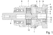
- In
der Figur 1 ist eine Schnittansicht eines erfindungsgemäßen Adapters gezeigt, der mit einem Getriebe verbunden ist.
- In the
FIG. 1 is a sectional view of an adapter according to the invention shown, which is connected to a transmission.
In der
In der
In der
In der
Der Adapter ist zwischen einem eintreibenden, in den Figuren nicht gezeigten Elektromotor und einem abtriebsseitigen Getriebe angeordnet.The adapter is arranged between a driving, not shown in the figures electric motor and a driven side gear.
Dabei wird das Motorgehäuse mit dem Adapterflansch 4 verbunden und die Rotorwelle des Motors in den Aufnahmebereich 13 der Adapterwelle 1 eingeführt und klemmverbunden.The motor housing is connected to the
Der Adapterflansch 4 ist mit dem Adaptergehäuseteil 5 verbunden, welches wiederum mit dem Getriebegehäuseteil 6 verbunden ist. Abtriebsseitig ist das Getriebegehäuseteil 7 mit dem Lagerflansch 8 verbunden, welcher die Lager der Abtriebswelle 9 des Getriebes aufnimmt.The
Somit ist die Adapterwelle 1 über die Rotorwelle im Motorgehäuse gelagert. Abtriebsseitig ist eine Sonnenradwelle 10 als eintreibende Welle des Getriebes mit der Adapterwelle 1 steckverbunden. Hierzu wird die Sonnenradwelle mit einem zylindrische und gerändelte und/oder verzahnte Bereich aufweisenden Zapfen in einen entsprechenden Aufnahmebereich der Adapterwelle 1 eingepresst.Thus, the
Das Adaptergehäuseteil 5 nimmt einen Wellendichtring 6 auf, dessen Dichtlippe gegen die Adapterwelle 1 abdichtet. Somit ist das Schmieröl des Getriebeinneren abgedichtet gegen den Innenraum des Adapters.The
Das Getriebe ist als Planetengetriebe ausgeführt, so dass die Sonnenradverzahnung der Sonnenradwelle 10 mit Planetenradverzahnungen im Eingriff steht, die wiederum mit einer Verzahnung eines Hohlrades im Eingriff stehen. Die Planeten sind an dem als Abtriebswelle 9 ausgeführten Planetenradträger gelagert.The gear is designed as a planetary gear, so that the Sonnenradverzahnung the
Der erste Gewindestift 3 und der weitere Gewindestift 11 sind im selben axialen Bereich angeordnet.The first threaded
Die Adapterwelle 1 weist in diesem axialen Bereich drei Abflachungen auf, die in Umfangsrichtung voneinander regelmäßig beabstandet sind. Durch die gleichmäßige Beabstandung der drei Abflachungen wird eine gleichmäßige Kraftverteilung erreicht. Die Aufnahme der Rotorwelle des Motors in dem Aufnahmebereich 13 der Adapterwelle erfolgt mittels kraftschlüssiger Verbindung, insbesondere Klemmverbindung.The
Hierzu wird der erste Gewindestift 3 durch eine radiale Gewindebohrung des Klemmrings 2 geschraubt, bis er auf die Adapterwelle 1 drückt. Hierbei ist ein derartiger Verdrehwinkel zwischen Adapterwelle 1 und Klemmring 2 vorgesehen, dass der erste Gewindestift 3 auf einen Bereich drückt, welcher in Umfangsrichtung symmetrisch zwischen zwei der Abflachungen der Adapterwelle 1 angeordnet ist. Da die Wandstärke der Adapterwelle 1 in diesem Bereich dicker ist als im Bereich der Abflachungen und somit die Adapterwelle 1 im Bereich der verdünnten Wandstärke, also im Beriech der Abflachungen, elastisch verformt wird, wird dieser dickere Bereich auf die Motorwelle gedrückt. Aufgrund der einwirkenden Druckkraft des ersten Gewindestifts 3 werden die beiden anderen, in Umfangsrichtung zwischen jeweiligen Abflachungen angeordneten ebenfalls dickeren Bereiche mittels der gebildeten Reaktionskräfte ebenfalls auf die Motorwelle gedrückt. Auf diese Weise wird die Motorwelle des Motors zentrisch geklemmt. Denn die am Umfang ausgebildeten drei Kraftdurchleitungsbereiche sind wegen der symmetrischen Anordnung der Abflachungen ebenfalls symmetrisch.For this purpose, the first threaded
Der Verdrehwinkel zwischen Adapterwelle 1 und Klemmring 2 wird mittels des weiteren Gewindestifts 11 gesichert. Hierzu wird vor der Verbindung der Motorwelle, also Rotorwelle des Motors, der Klemmring 2 auf die Adapterwelle 1 aufgesteckt und der weitere Gewindestift 11 durch eine weitere Gewindebohrung des Klemmrings 2 geschraubt, bis er eine der Abflachungen der Adapterwelle 1 berührt. Auf diese Weise wird der Klemmring 2 gegenüber der Adapterwelle 1 verdrehgesichert. Für diese Verdrehsicherung muss von dem weiteren Gewindestift 11 keine hohe radial wirkende Druckkraft eingeleitet werden, weshalb der der Abflachung zugeordnete mit verdünnter Wandstärke ausgeführte Bereich nicht mit hohen Kräften belastet wird. Der weitere Gewindestift 11 hat nur die Funktion, an der Abflachung der Adapterwelle anzuliegen und somit als Verdrehsicherungsmittel an der Abflachung zu wirken.The angle of rotation between the
Beim Verhinderung von Verwechslungsgefahr weist der erste Gewindestift 3 und der weitere Gewindestift 11 eine unterschiedliche Werkzeugaufnahme für Werkzeuge auf. Beispielsweise weist der erste Gewindestift 3 einen Kreuzschlitzaufnahmebereich auf und der weitere Gewindestift einen Aufnahmebereich für einen Schlitzschraubendreher.In preventing the risk of confusion, the first threaded
Der Klemmring 2 wird aus axialer Richtung kommend auf die Adapterwelle 1 aufgesteckt und in den Adapterflansch 4 eingesteckt. Dabei ragt der erste Gewindestift 3 aus dem Klemmring 2 nach radial außen heraus. Ein axial verlaufender Schlitz 30, insbesondere Axialnut, im Adapterflansch 4 ist zur Ermöglichung des Einführens im Adapterflansch 4 vorgesehen. Am inneren Endbereich des Schlitzes 30, welcher also in der Innenwandung des Aufnahmebereichs eingearbeitet ist, mündet eine radial verlaufend Bohrung 14, durch welche ein Werkzeug zur Betätigung des ersten Gewindestiftes 3 einführbar ist. Somit ist als Transportsicherung und Lagersicherung mittels des in den Schlitz 30 zumindest teilweise hineinragenden Gewindestiftes 3 eine Verdrehsicherung der Adapterwelle 1 im Adapterflansch 4 ausgeführt. Zur axialen Sicherung des Klemmrings 2 auf der Adapterwelle 1 ist ein Sicherungsring 12 auf der Adapterwelle 1 angeordnet.The
Zwischen Adapter und Getriebe ist ein fester spielfreier Einpass vorgesehen. Somit ist also das Motorgehäuse beim Verbinden mit dem Adapterflansch 4 spielfrei festgelegt. Ein Ausrichten der Welle ist nicht notwendig, da beim Verbinden die Motorwelle in den Aufnahmebereich 30 der Adapterwelle 1 eingeschoben wird und dann mittels des Gewindestiftes 3 die Klemmverbindung aktiviert wird. Auf diese Weise ist also eine schnelle und einfache Fertigung erreichbar. In gleicher Weise ist auch ein fester spielfreier Einpass zwischen Adapterflansch 4 und Adaptergehäuseteil 5 vorgesehen. Zwischen Getriebegehäuse und Adaptergehäuseteil 5 ist ebenfalls ein solcher spielfreier Einpass vorgesehen. Somit sind also die Gehäuseteile des Getriebemotors fest und spielfrei verbindbar, ohne dass ein Ausrichten erforderlich ist. Vorteiligerweise entfällt auch ein Ausrichten der Adapterwelle 1 gegenüber der Motorwelle.Between adapter and gearbox, a fixed backlash-free fitting is provided. Thus, therefore, the motor housing is fixed without play when connecting to the
Die Adapterwelle 1 ist statisch bestimmt gelagert.The
Zur axialen Sicherung, insbesondere zur axialen Lagepositionierung des Klemmrings 2 beim Einschrauben des Gewindestiftes 3, ist am Adapterflansch 4 ein Sicherungsring 15 angeordnet. Zur Anpassung einer zu großen Ausnehmung im Sicherungsring 15 ist axial neben dem Sicherungsring 15 ein Stützscheibe 50 angeordnet. Somit ist während des Einschraubens des Gewindestiftes 3 ein Anlegen des Gewindestiftes 3 an die Stützscheibe 50 ermöglicht. Wenn der Gewindestift schon weitgehend eingeschraubt ist, aber noch nicht auf die Adapterwelle genügend stark drückt, ist die axiale Sicherung zwar nicht mehr durch den Sicherungsring 15 mit Stützscheibe 50 gewährleistet, jedoch ist dann noch die spielbehaftete axiale Sicherung mittels des Sicherungsrings 52 auf der Adapterwelle 1 samt der Wellenschulter 51 der Adapterwelle 1 wirksam.For axial securing, in particular for the axial position positioning of the
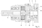
Wie in
Statt des genannten Planetengetriebes ist auch ein beliebig anderes Getriebe erfindungsgemäß einsetzbar. Daher ist die Erfindung auch ganz allgemein an einer Welle-Nabe-Verbindung ausführbar, wobei die Adapterwelle 1 die Nabe ist und die Motorwelle die zu verbindende Welle.Instead of said planetary gear and any other gear according to the invention can be used. Therefore, the invention is also quite generally executable on a shaft-hub connection, wherein the
Bei einem weiteren erfindungsgemäßen Ausführungsbeispiel wird zur Durchmesseranpassung anstatt der genannten Motorwelle, also Rotorwelle, eine Hülse auf die Motorwelle aufgesteckt und die Motorwelle samt Hülse in den Aufnahmebereich 30 der Nabe, insbesondere der Adapterwelle, eingeführt.In a further embodiment of the invention, a sleeve is fitted to the motor shaft for diameter adjustment instead of said motor shaft, so rotor shaft, and the motor shaft including sleeve in the receiving
Bei einem weiteren erfindungsgemäßen Ausführungsbeispiel sind statt Motor und/oder Getriebe andere Vorrichtungen mit dem Adapter verbunden. Dabei ist die Adapterwelle wiederum gelagert über die eintreibende Welle der eintriebsseitigen, statt des Motors eingesetzten Vorrichtung. Statt der Sonnenradwelle 10 ist somit auch ein anderes Wellenstück mit der Adapterwelle 1 verbindbar und über diese und die eintreibende Welle in der eintreibenden Vorrichtung lagerbar.In a further embodiment of the invention, other devices are connected to the adapter instead of the engine and / or transmission. In this case, the adapter shaft is in turn mounted on the driving shaft of the input side, used instead of the motor device. Instead of the
Bei einem weiteren erfindungsgemäßen Ausführungsbeispiel wird statt des eine Abflachung berührenden weiteren Gewindestiftes 11 eine andere Art der Verdrehsicherung ausgeführt. Beispielsweise wird der Klemmring 2 mit einer entsprechend der Abflachung der Adapterwelle 1 ausgeführten ebenen Abschnitt der Innenwandung ausgeführt. Somit liegt dann der Klemmring 2 an der Adapterwelle 1 berührend an und der Verdrehwinkel ist ebenfalls gesichert. Der Klemmring 2 ist auch an seiner der Adapterwelle 1 zugewandten Innenwandung polygonal ausgeführt oder zumindest mit regelmäßig voneinander beabstandeten Abflachungen ausgeführt. Somit liegt der Klemmring 2 zumindest im Bereich einer oder mehrerer Abflachungen berührend an und ist zur Adapterwelle verdrehgesichert.In a further embodiment of the invention, a different type of anti-rotation is carried out instead of a flattening another touching threaded
Bei einem weiteren erfindungsgemäßen Ausführungsbeispiel wird statt des eine Abflachung berührenden weiteren Gewindestiftes 11 eine Madenschraube durch eine Gewindebohrung des Klemmrings 2 geschraubt und somit eine Verdrehsicherung geschaffen. Somit wirkt dann die Madenschraube als Verdrehsicherungsmittel.In a further embodiment of the invention, a grub screw is screwed through a threaded bore of the
Zur axialen Sicherung, insbesondere zur axialen Lagepositionierung des Klemmrings 2 beim Einschrauben des Gewindestiftes 3, ist am Adapterflansch 4 ein Sicherungsring 15 angeordnet.For axial securing, in particular for the axial position positioning of the
- 11
- Adapterwelleadapter shaft
- 22
- Klemmringclamping ring
- 33
- GewindestiftSet screw
- 44
- Adapterflanschadapter flange
- 55
- AdaptergehäuseteilAdapter housing part
- 66
- WellendichtringShaft seal
- 77
- GetriebegehäuseteilGear housing part
- 88th
- LagerflanschLagerflansch
- 99
- Abtriebswelleoutput shaft
- 1010
- Sonnenradwellesun
- 1111
- weiterer Gewindestiftanother grub screw
- 1212
- Sicherungsringcirclip
- 1313
- Aufnahmebereichreception area
- 1414
-
Bohrung zur Betätigung des Gewindestifts 3Bore for actuating the threaded
pin 3 - 1515
-
Sicherungsring am Adapterflansch 4Circlip on
adapter flange 4 - 3030
- Axialnutaxial groove
- 5050
- Stützscheibesupport disc
- 5151
- Wellenschultershaft shoulder
- 5252
-
Sicherungsring auf Adapterwelle 1Circlip on
adapter shaft 1 - 7171
- Gewindeabschnitt des GewindestiftesThread section of the threaded pin
- 7272
- Zapfenabschnittjournal section
- 7373
- Klemmringclamping ring
Claims (15)
- A shaft-hub connection,
wherein a shaft, in particular motor shaft, is introduced into a receiving region (13) of a hub, in particular adapter shaft (1), and is connected in non-positive manner, in particular connected by clamping,
characterised in that
the hub, at least in an axial region, has three flattened portions, spaced apart regularly from each other in the circumferential direction,
wherein a first screwing part (3) is screwed into a clamping ring (2, 73) and presses on a region of the hub in order to bring about the non-positive connection,
wherein the region in the circumferential direction is arranged centrally between two of the flattened portions. - A shaft-hub connection according to Claim 1,
characterised in that
the flattened portions are arranged on the outside of the hub which is remote from the shaft. - A shaft-hub connection according to at least one of the preceding claims, characterised in that
the clamping ring (2, 73) is connected to the hub in rotation-resistant manner,
the flattened portions being arranged between the clamping ring (2, 73) and the hub. - A shaft-hub connection according to at least one of the preceding claims, characterised in that
the region covers an angle-at-circumference range which is smaller than the angular distance in the circumferential direction between two flattened portions next adjacent in the circumferential direction. - A shaft-hub connection according to at least one of the preceding claims, characterised in that
the hub in this region has a greater wall thickness than in the region of a respective flattened portion. - A shaft-hub connection according to at least one of the preceding claims, characterised in that
a further screwing part or a flattened portion which corresponds to at least one of the flattened portions of the hub or a flat inner wall portion corresponding to at least one of the flattened portions of the hub is provided on the clamping ring (2, 73) as anti-twist protection means. - A shaft-hub connection according to at least one of the preceding claims, characterised in that
the clamping ring (2, 73) has a flattened portion on its inner wall facing the hub as anti-twist protection means. - A shaft-hub connection according to at least one of the preceding claims, characterised in that
the hub is arranged radially between the shaft and clamping ring (2, 73). - A shaft-hub connection according to one of Claims 6, 7 or 8,
characterised in that
the receiving region (13) for actuating the first screwing part is embodied differently from the receiving region (13) for actuating the anti-twist protection means,
so that a different tool for actuating the first screwing part is necessary than for actuating the anti-twist protection means. - A shaft-hub connection according to at least one of the preceding claims, characterised in that
a securing ring (12) for axially securing the clamping ring (2, 73) is arranged on the hub. - A shaft-hub connection according to at least one of the preceding claims, characterised in that
the first screwing part is provided as acting in the circumferential direction. - A shaft-hub connection according to at least one of the preceding claims, characterised in that
the hub plus the clamping ring (2, 73) is mounted via the shaft in a further housing part
and/or in that
the clamping ring (2, 73) is secured on the hub by means of an anti-twist protection means such that the first screwing part is pressed against the hub centrally in the circumferential direction between two adjacent flattened portions. - A shaft-hub connection according to at least one of the preceding claims, characterised in that
the clamping ring (2, 73) is placed on the hub from the axial direction, so that the hub can be clamped to the shaft. - An adapter with a shaft-hub connection according to at least one of the preceding claims,
characterised in that
the shaft-hub connection is at least partially surrounded by an adapter flange (4) and/or adapter housing part (5). - A gear motor with an adapter according to Claim 14.
Applications Claiming Priority (2)
| Application Number | Priority Date | Filing Date | Title |
|---|---|---|---|
| DE102012000537.7A DE102012000537B4 (en) | 2012-01-16 | 2012-01-16 | Shaft-hub connection, adapter and geared motor |
| PCT/EP2012/004923 WO2013107476A1 (en) | 2012-01-16 | 2012-11-29 | Shaft-hub connection, adapter and geared motor |
Publications (2)
| Publication Number | Publication Date |
|---|---|
| EP2805078A1 EP2805078A1 (en) | 2014-11-26 |
| EP2805078B1 true EP2805078B1 (en) | 2016-10-26 |
Family
ID=47504787
Family Applications (1)
| Application Number | Title | Priority Date | Filing Date |
|---|---|---|---|
| EP12810069.0A Active EP2805078B1 (en) | 2012-01-16 | 2012-11-29 | Shaft-hub coupling, adapter and drive motor |
Country Status (5)
| Country | Link |
|---|---|
| US (1) | US9945426B2 (en) |
| EP (1) | EP2805078B1 (en) |
| CN (1) | CN104053919B (en) |
| DE (1) | DE102012000537B4 (en) |
| WO (1) | WO2013107476A1 (en) |
Families Citing this family (7)
| Publication number | Priority date | Publication date | Assignee | Title |
|---|---|---|---|---|
| DE102014007063A1 (en) * | 2013-05-23 | 2014-11-27 | Sew-Eurodrive Gmbh & Co Kg | Shaft-hub connection and geared motor |
| DE102014005415B4 (en) * | 2014-04-14 | 2020-02-13 | Sew-Eurodrive Gmbh & Co Kg | Bearing arrangement for a transmission and method for adjusting the preload of a bearing arrangement |
| DE102015005360B3 (en) * | 2015-04-28 | 2016-06-23 | Sew-Eurodrive Gmbh & Co Kg | transmission system |
| CN109952456B (en) * | 2016-11-11 | 2022-07-08 | 索尤若驱动有限及两合公司 | Speed reducer with first and second housing parts |
| WO2018233875A1 (en) * | 2017-06-22 | 2018-12-27 | Sew-Eurodrive Gmbh & Co. Kg | Coupling comprising a shaft inserted at least partially into a hollow shaft and a ring slipped onto the hollow shaft, and planetary gearset |
| CN111051718A (en) | 2017-09-08 | 2020-04-21 | 索尤若驱动有限及两合公司 | Device for the force-locking connection of an adapter shaft to a shaft by means of a clamping ring |
| EP3679261B1 (en) * | 2017-09-08 | 2021-11-24 | SEW-EURODRIVE GmbH & Co. KG | Assembly for connecting an adapter shaft to a shaft in a force-fitting manner using a clamping ring |
Citations (1)
| Publication number | Priority date | Publication date | Assignee | Title |
|---|---|---|---|---|
| US3598432A (en) * | 1969-10-20 | 1971-08-10 | Designatronics Inc | Hub clamp |
Family Cites Families (19)
| Publication number | Priority date | Publication date | Assignee | Title |
|---|---|---|---|---|
| DE137669C (en) | ||||
| US2464077A (en) * | 1944-11-23 | 1949-03-08 | Byron R Dicks | Multiple pulley mount |
| US2432860A (en) * | 1945-02-01 | 1947-12-16 | Homer C Clatfelter | Adapter |
| GB776357A (en) | 1954-05-12 | 1957-06-05 | Cam Gears Ltd | Improvements in means for connecting the parts of steering gear |
| US2804322A (en) * | 1954-11-23 | 1957-08-27 | Herzog Carl | Rotary element and shaft assembly |
| BE550753A (en) | 1955-10-05 | |||
| US3160429A (en) * | 1959-05-26 | 1964-12-08 | Martins Borge | Device for fastening a hub to a shaft |
| US3879046A (en) * | 1974-01-07 | 1975-04-22 | Babb Engineering Company | Rotary tool holders |
| US4006993A (en) * | 1975-11-25 | 1977-02-08 | Borg-Warner Corporation | Shaft mounting arrangement |
| DE3025898A1 (en) * | 1980-07-09 | 1982-02-11 | Karl Schmidt Gmbh, 7107 Neckarsulm | AXIAL ADJUSTABLE STEERING WHEEL FOR VEHICLES |
| GB8502873D0 (en) * | 1985-02-05 | 1985-03-06 | Hartridge Ltd Leslie | Securing means |
| GB2273143B (en) | 1992-12-02 | 1996-01-03 | Ripponlea Australia Pty Ltd | Lock accessories |
| US6260437B1 (en) * | 1999-04-08 | 2001-07-17 | Delphi Technologies, Inc. | Steering wheel attachment |
| US7059457B2 (en) * | 2003-10-06 | 2006-06-13 | Lee Lanny R | Expansion motor |
| US20060035746A1 (en) * | 2004-08-12 | 2006-02-16 | Griggs Steven H | Drive shaft assembly and method of separation |
| DE102007043319B4 (en) * | 2007-09-12 | 2009-08-13 | WINKLER+DüNNEBIER AG | Device for transmitting torque to a shaft |
| US8944718B2 (en) * | 2010-09-23 | 2015-02-03 | C-Flex Bearing Co., Inc. | Clamping bushing |
| DE102013208568A1 (en) * | 2013-05-08 | 2014-11-13 | Lenze Drives Gmbh | Arrangement with hollow shaft, drive shaft and clamping device |
| DE102014007063A1 (en) * | 2013-05-23 | 2014-11-27 | Sew-Eurodrive Gmbh & Co Kg | Shaft-hub connection and geared motor |
-
2012
- 2012-01-16 DE DE102012000537.7A patent/DE102012000537B4/en active Active
- 2012-11-29 EP EP12810069.0A patent/EP2805078B1/en active Active
- 2012-11-29 WO PCT/EP2012/004923 patent/WO2013107476A1/en active Application Filing
- 2012-11-29 CN CN201280067194.6A patent/CN104053919B/en active Active
- 2012-11-29 US US14/372,639 patent/US9945426B2/en active Active
Patent Citations (1)
| Publication number | Priority date | Publication date | Assignee | Title |
|---|---|---|---|---|
| US3598432A (en) * | 1969-10-20 | 1971-08-10 | Designatronics Inc | Hub clamp |
Also Published As
| Publication number | Publication date |
|---|---|
| CN104053919A (en) | 2014-09-17 |
| WO2013107476A8 (en) | 2014-07-24 |
| US9945426B2 (en) | 2018-04-17 |
| DE102012000537A1 (en) | 2013-07-18 |
| WO2013107476A1 (en) | 2013-07-25 |
| EP2805078A1 (en) | 2014-11-26 |
| CN104053919B (en) | 2017-02-08 |
| US20150300414A1 (en) | 2015-10-22 |
| DE102012000537B4 (en) | 2014-08-07 |
Similar Documents
| Publication | Publication Date | Title |
|---|---|---|
| EP2805078B1 (en) | Shaft-hub coupling, adapter and drive motor | |
| DE102019003546A1 (en) | Adapter for a drive and drive | |
| EP2999895B1 (en) | Shaft-hub connection and gear motor | |
| EP3022465A1 (en) | Transmission having a first and a second housing part | |
| EP2834538B1 (en) | Gearbox with a first and a second housing part | |
| EP1664564B1 (en) | System for connecting a shaft to a joint | |
| EP3538783B1 (en) | Gear motor comprising a gear mechanism driven by an electric motor | |
| EP4130515B1 (en) | Driving device for an adjustable vehicle door | |
| EP3308055A1 (en) | Gearing having a housing and a planetary gearing stage | |
| DE102019121755A1 (en) | Multi-part actuator | |
| EP1360753B1 (en) | Toothed piece for a geared motor, series of geared motors and connection | |
| WO2018086754A1 (en) | Gear motor comprising a gear mechanism driven by an electric motor | |
| DE102014002629B4 (en) | System for adjusting a bearing arrangement for a transmission with a tool | |
| DE102008026806B4 (en) | drive | |
| EP3947998B1 (en) | Clamping connection with a clamping ring mounted on a hub, in particular a hollow shaft section, comprising a screw, in particular a clamping screw | |
| EP3948000B1 (en) | Clamping connection comprising a clamping ring mounted on a hub, particularly a hollow shaft section, with a screw, particularly a clamping screw | |
| LU101812B1 (en) | Coupling device and method for torque-transmitting coupling of a drive device to a transmission | |
| EP3538791B1 (en) | Transmission comprising a first housing part and a second housing part | |
| DE102014214056A1 (en) | Connecting arrangement between a shaft member and a hub member | |
| DE102017009860A1 (en) | planetary gear | |
| WO2020164801A1 (en) | Assembly for clamping connection of a shaft, planetary gearbox and method for production | |
| EP3749874A1 (en) | Method for the clamping connection of a hollow shaft region to a shaft by means of a clamping ring, and arrangement for carrying out the method | |
| DE102016012978A1 (en) | Planetary gear with a planet carrier and a Planetenradachse | |
| DE102007054575A1 (en) | Spur gear coupling with drive element and driven element where the drive element includes first and second spur and assembly housing useful in internal combustion engine technology simple to assemble at low cost | |
| DE102012205609A1 (en) | Electric hand tool with spindle stop |
Legal Events
| Date | Code | Title | Description |
|---|---|---|---|
| PUAI | Public reference made under article 153(3) epc to a published international application that has entered the european phase |
Free format text: ORIGINAL CODE: 0009012 |
|
| 17P | Request for examination filed |
Effective date: 20140818 |
|
| AK | Designated contracting states |
Kind code of ref document: A1 Designated state(s): AL AT BE BG CH CY CZ DE DK EE ES FI FR GB GR HR HU IE IS IT LI LT LU LV MC MK MT NL NO PL PT RO RS SE SI SK SM TR |
|
| DAX | Request for extension of the european patent (deleted) | ||
| 17Q | First examination report despatched |
Effective date: 20150928 |
|
| GRAP | Despatch of communication of intention to grant a patent |
Free format text: ORIGINAL CODE: EPIDOSNIGR1 |
|
| INTG | Intention to grant announced |
Effective date: 20160624 |
|
| GRAS | Grant fee paid |
Free format text: ORIGINAL CODE: EPIDOSNIGR3 |
|
| GRAA | (expected) grant |
Free format text: ORIGINAL CODE: 0009210 |
|
| AK | Designated contracting states |
Kind code of ref document: B1 Designated state(s): AL AT BE BG CH CY CZ DE DK EE ES FI FR GB GR HR HU IE IS IT LI LT LU LV MC MK MT NL NO PL PT RO RS SE SI SK SM TR |
|
| REG | Reference to a national code |
Ref country code: GB Ref legal event code: FG4D Free format text: NOT ENGLISH |
|
| REG | Reference to a national code |
Ref country code: FR Ref legal event code: PLFP Year of fee payment: 5 |
|
| REG | Reference to a national code |
Ref country code: CH Ref legal event code: EP |
|
| REG | Reference to a national code |
Ref country code: AT Ref legal event code: REF Ref document number: 840250 Country of ref document: AT Kind code of ref document: T Effective date: 20161115 |
|
| REG | Reference to a national code |
Ref country code: IE Ref legal event code: FG4D Free format text: LANGUAGE OF EP DOCUMENT: GERMAN |
|
| REG | Reference to a national code |
Ref country code: DE Ref legal event code: R096 Ref document number: 502012008643 Country of ref document: DE |
|
| REG | Reference to a national code |
Ref country code: NL Ref legal event code: FP |
|
| REG | Reference to a national code |
Ref country code: LT Ref legal event code: MG4D |
|
| PG25 | Lapsed in a contracting state [announced via postgrant information from national office to epo] |
Ref country code: BE Free format text: LAPSE BECAUSE OF NON-PAYMENT OF DUE FEES Effective date: 20161130 Ref country code: LV Free format text: LAPSE BECAUSE OF FAILURE TO SUBMIT A TRANSLATION OF THE DESCRIPTION OR TO PAY THE FEE WITHIN THE PRESCRIBED TIME-LIMIT Effective date: 20161026 |
|
| PG25 | Lapsed in a contracting state [announced via postgrant information from national office to epo] |
Ref country code: LT Free format text: LAPSE BECAUSE OF FAILURE TO SUBMIT A TRANSLATION OF THE DESCRIPTION OR TO PAY THE FEE WITHIN THE PRESCRIBED TIME-LIMIT Effective date: 20161026 Ref country code: SE Free format text: LAPSE BECAUSE OF FAILURE TO SUBMIT A TRANSLATION OF THE DESCRIPTION OR TO PAY THE FEE WITHIN THE PRESCRIBED TIME-LIMIT Effective date: 20161026 Ref country code: NO Free format text: LAPSE BECAUSE OF FAILURE TO SUBMIT A TRANSLATION OF THE DESCRIPTION OR TO PAY THE FEE WITHIN THE PRESCRIBED TIME-LIMIT Effective date: 20170126 Ref country code: GR Free format text: LAPSE BECAUSE OF FAILURE TO SUBMIT A TRANSLATION OF THE DESCRIPTION OR TO PAY THE FEE WITHIN THE PRESCRIBED TIME-LIMIT Effective date: 20170127 |
|
| PG25 | Lapsed in a contracting state [announced via postgrant information from national office to epo] |
Ref country code: ES Free format text: LAPSE BECAUSE OF FAILURE TO SUBMIT A TRANSLATION OF THE DESCRIPTION OR TO PAY THE FEE WITHIN THE PRESCRIBED TIME-LIMIT Effective date: 20161026 Ref country code: HR Free format text: LAPSE BECAUSE OF FAILURE TO SUBMIT A TRANSLATION OF THE DESCRIPTION OR TO PAY THE FEE WITHIN THE PRESCRIBED TIME-LIMIT Effective date: 20161026 Ref country code: RS Free format text: LAPSE BECAUSE OF FAILURE TO SUBMIT A TRANSLATION OF THE DESCRIPTION OR TO PAY THE FEE WITHIN THE PRESCRIBED TIME-LIMIT Effective date: 20161026 Ref country code: PT Free format text: LAPSE BECAUSE OF FAILURE TO SUBMIT A TRANSLATION OF THE DESCRIPTION OR TO PAY THE FEE WITHIN THE PRESCRIBED TIME-LIMIT Effective date: 20170227 Ref country code: FI Free format text: LAPSE BECAUSE OF FAILURE TO SUBMIT A TRANSLATION OF THE DESCRIPTION OR TO PAY THE FEE WITHIN THE PRESCRIBED TIME-LIMIT Effective date: 20161026 Ref country code: IS Free format text: LAPSE BECAUSE OF FAILURE TO SUBMIT A TRANSLATION OF THE DESCRIPTION OR TO PAY THE FEE WITHIN THE PRESCRIBED TIME-LIMIT Effective date: 20170226 Ref country code: PL Free format text: LAPSE BECAUSE OF FAILURE TO SUBMIT A TRANSLATION OF THE DESCRIPTION OR TO PAY THE FEE WITHIN THE PRESCRIBED TIME-LIMIT Effective date: 20161026 |
|
| REG | Reference to a national code |
Ref country code: CH Ref legal event code: PL |
|
| REG | Reference to a national code |
Ref country code: DE Ref legal event code: R097 Ref document number: 502012008643 Country of ref document: DE |
|
| PG25 | Lapsed in a contracting state [announced via postgrant information from national office to epo] |
Ref country code: MC Free format text: LAPSE BECAUSE OF FAILURE TO SUBMIT A TRANSLATION OF THE DESCRIPTION OR TO PAY THE FEE WITHIN THE PRESCRIBED TIME-LIMIT Effective date: 20161026 Ref country code: DK Free format text: LAPSE BECAUSE OF FAILURE TO SUBMIT A TRANSLATION OF THE DESCRIPTION OR TO PAY THE FEE WITHIN THE PRESCRIBED TIME-LIMIT Effective date: 20161026 Ref country code: CZ Free format text: LAPSE BECAUSE OF FAILURE TO SUBMIT A TRANSLATION OF THE DESCRIPTION OR TO PAY THE FEE WITHIN THE PRESCRIBED TIME-LIMIT Effective date: 20161026 Ref country code: EE Free format text: LAPSE BECAUSE OF FAILURE TO SUBMIT A TRANSLATION OF THE DESCRIPTION OR TO PAY THE FEE WITHIN THE PRESCRIBED TIME-LIMIT Effective date: 20161026 Ref country code: SK Free format text: LAPSE BECAUSE OF FAILURE TO SUBMIT A TRANSLATION OF THE DESCRIPTION OR TO PAY THE FEE WITHIN THE PRESCRIBED TIME-LIMIT Effective date: 20161026 Ref country code: CH Free format text: LAPSE BECAUSE OF NON-PAYMENT OF DUE FEES Effective date: 20161130 Ref country code: LI Free format text: LAPSE BECAUSE OF NON-PAYMENT OF DUE FEES Effective date: 20161130 Ref country code: RO Free format text: LAPSE BECAUSE OF FAILURE TO SUBMIT A TRANSLATION OF THE DESCRIPTION OR TO PAY THE FEE WITHIN THE PRESCRIBED TIME-LIMIT Effective date: 20161026 |
|
| REG | Reference to a national code |
Ref country code: IE Ref legal event code: MM4A |
|
| PG25 | Lapsed in a contracting state [announced via postgrant information from national office to epo] |
Ref country code: SM Free format text: LAPSE BECAUSE OF FAILURE TO SUBMIT A TRANSLATION OF THE DESCRIPTION OR TO PAY THE FEE WITHIN THE PRESCRIBED TIME-LIMIT Effective date: 20161026 Ref country code: BG Free format text: LAPSE BECAUSE OF FAILURE TO SUBMIT A TRANSLATION OF THE DESCRIPTION OR TO PAY THE FEE WITHIN THE PRESCRIBED TIME-LIMIT Effective date: 20170126 |
|
| PLBE | No opposition filed within time limit |
Free format text: ORIGINAL CODE: 0009261 |
|
| STAA | Information on the status of an ep patent application or granted ep patent |
Free format text: STATUS: NO OPPOSITION FILED WITHIN TIME LIMIT |
|
| PG25 | Lapsed in a contracting state [announced via postgrant information from national office to epo] |
Ref country code: LU Free format text: LAPSE BECAUSE OF NON-PAYMENT OF DUE FEES Effective date: 20161130 |
|
| 26N | No opposition filed |
Effective date: 20170727 |
|
| REG | Reference to a national code |
Ref country code: FR Ref legal event code: PLFP Year of fee payment: 6 |
|
| PG25 | Lapsed in a contracting state [announced via postgrant information from national office to epo] |
Ref country code: SI Free format text: LAPSE BECAUSE OF FAILURE TO SUBMIT A TRANSLATION OF THE DESCRIPTION OR TO PAY THE FEE WITHIN THE PRESCRIBED TIME-LIMIT Effective date: 20161026 Ref country code: IE Free format text: LAPSE BECAUSE OF NON-PAYMENT OF DUE FEES Effective date: 20161129 |
|
| REG | Reference to a national code |
Ref country code: BE Ref legal event code: MM Effective date: 20161130 |
|
| PG25 | Lapsed in a contracting state [announced via postgrant information from national office to epo] |
Ref country code: HU Free format text: LAPSE BECAUSE OF FAILURE TO SUBMIT A TRANSLATION OF THE DESCRIPTION OR TO PAY THE FEE WITHIN THE PRESCRIBED TIME-LIMIT; INVALID AB INITIO Effective date: 20121129 |
|
| PG25 | Lapsed in a contracting state [announced via postgrant information from national office to epo] |
Ref country code: CY Free format text: LAPSE BECAUSE OF FAILURE TO SUBMIT A TRANSLATION OF THE DESCRIPTION OR TO PAY THE FEE WITHIN THE PRESCRIBED TIME-LIMIT Effective date: 20161026 Ref country code: MK Free format text: LAPSE BECAUSE OF FAILURE TO SUBMIT A TRANSLATION OF THE DESCRIPTION OR TO PAY THE FEE WITHIN THE PRESCRIBED TIME-LIMIT Effective date: 20161026 |
|
| PG25 | Lapsed in a contracting state [announced via postgrant information from national office to epo] |
Ref country code: MT Free format text: LAPSE BECAUSE OF FAILURE TO SUBMIT A TRANSLATION OF THE DESCRIPTION OR TO PAY THE FEE WITHIN THE PRESCRIBED TIME-LIMIT Effective date: 20161026 |
|
| REG | Reference to a national code |
Ref country code: FR Ref legal event code: PLFP Year of fee payment: 7 |
|
| PG25 | Lapsed in a contracting state [announced via postgrant information from national office to epo] |
Ref country code: TR Free format text: LAPSE BECAUSE OF FAILURE TO SUBMIT A TRANSLATION OF THE DESCRIPTION OR TO PAY THE FEE WITHIN THE PRESCRIBED TIME-LIMIT Effective date: 20161026 |
|
| REG | Reference to a national code |
Ref country code: AT Ref legal event code: MM01 Ref document number: 840250 Country of ref document: AT Kind code of ref document: T Effective date: 20171129 |
|
| PG25 | Lapsed in a contracting state [announced via postgrant information from national office to epo] |
Ref country code: AT Free format text: LAPSE BECAUSE OF NON-PAYMENT OF DUE FEES Effective date: 20171129 |
|
| PG25 | Lapsed in a contracting state [announced via postgrant information from national office to epo] |
Ref country code: AL Free format text: LAPSE BECAUSE OF FAILURE TO SUBMIT A TRANSLATION OF THE DESCRIPTION OR TO PAY THE FEE WITHIN THE PRESCRIBED TIME-LIMIT Effective date: 20161026 |
|
| PGFP | Annual fee paid to national office [announced via postgrant information from national office to epo] |
Ref country code: NL Payment date: 20231016 Year of fee payment: 12 Ref country code: FR Payment date: 20230929 Year of fee payment: 12 |
|
| PGFP | Annual fee paid to national office [announced via postgrant information from national office to epo] |
Ref country code: GB Payment date: 20231006 Year of fee payment: 12 |
|
| PGFP | Annual fee paid to national office [announced via postgrant information from national office to epo] |
Ref country code: IT Payment date: 20231010 Year of fee payment: 12 Ref country code: DE Payment date: 20231130 Year of fee payment: 12 |