CN1004105B - Rotating speed signal transmitter - Google Patents
Rotating speed signal transmitter Download PDFInfo
- Publication number
- CN1004105B CN1004105B CN86108532.9A CN86108532A CN1004105B CN 1004105 B CN1004105 B CN 1004105B CN 86108532 A CN86108532 A CN 86108532A CN 1004105 B CN1004105 B CN 1004105B
- Authority
- CN
- China
- Prior art keywords
- rotating speed
- signalling generator
- stator
- rotor
- fixed
- Prior art date
- Legal status (The legal status is an assumption and is not a legal conclusion. Google has not performed a legal analysis and makes no representation as to the accuracy of the status listed.)
- Expired
Links
- 230000011664 signaling Effects 0.000 claims description 59
- 230000008878 coupling Effects 0.000 claims description 20
- 238000010168 coupling process Methods 0.000 claims description 20
- 238000005859 coupling reaction Methods 0.000 claims description 20
- 238000009434 installation Methods 0.000 claims description 7
- 230000000694 effects Effects 0.000 claims description 4
- 239000004033 plastic Substances 0.000 claims description 4
- 229920003023 plastic Polymers 0.000 claims description 4
- 210000004907 gland Anatomy 0.000 claims description 2
- 201000007094 prostatitis Diseases 0.000 claims 4
- 230000002441 reversible effect Effects 0.000 abstract description 7
- 230000005540 biological transmission Effects 0.000 abstract 1
- 238000010276 construction Methods 0.000 abstract 1
- 230000008901 benefit Effects 0.000 description 4
- 238000000034 method Methods 0.000 description 4
- 238000005259 measurement Methods 0.000 description 3
- 238000000354 decomposition reaction Methods 0.000 description 2
- 238000013461 design Methods 0.000 description 2
- 238000004519 manufacturing process Methods 0.000 description 2
- 230000007704 transition Effects 0.000 description 2
- 229910000831 Steel Inorganic materials 0.000 description 1
- 230000009471 action Effects 0.000 description 1
- 238000005452 bending Methods 0.000 description 1
- 230000008859 change Effects 0.000 description 1
- 230000000295 complement effect Effects 0.000 description 1
- 238000002788 crimping Methods 0.000 description 1
- 230000001419 dependent effect Effects 0.000 description 1
- 238000006073 displacement reaction Methods 0.000 description 1
- 239000000428 dust Substances 0.000 description 1
- 230000007774 longterm Effects 0.000 description 1
- 238000012423 maintenance Methods 0.000 description 1
- 230000013011 mating Effects 0.000 description 1
- 230000003287 optical effect Effects 0.000 description 1
- 230000008520 organization Effects 0.000 description 1
- 238000012856 packing Methods 0.000 description 1
- 230000008569 process Effects 0.000 description 1
- 239000007787 solid Substances 0.000 description 1
- 239000010959 steel Substances 0.000 description 1
- 238000003466 welding Methods 0.000 description 1
Images
Classifications
-
- G—PHYSICS
- G01—MEASURING; TESTING
- G01P—MEASURING LINEAR OR ANGULAR SPEED, ACCELERATION, DECELERATION, OR SHOCK; INDICATING PRESENCE, ABSENCE, OR DIRECTION, OF MOVEMENT
- G01P1/00—Details of instruments
- G01P1/04—Special adaptations of driving means
Landscapes
- Physics & Mathematics (AREA)
- General Physics & Mathematics (AREA)
- Connection Of Motors, Electrical Generators, Mechanical Devices, And The Like (AREA)
- Lubricants (AREA)
- Crystals, And After-Treatments Of Crystals (AREA)
- Inorganic Insulating Materials (AREA)
- Piezo-Electric Or Mechanical Vibrators, Or Delay Or Filter Circuits (AREA)
- Thermistors And Varistors (AREA)
- Golf Clubs (AREA)
- Transmission And Conversion Of Sensor Element Output (AREA)
- Oscillators With Electromechanical Resonators (AREA)
- Steroid Compounds (AREA)
Abstract
A short-structure rotational speed transmitter has a hollow connecting shaft and a clamping element for fixing the hollow connecting shaft to a rotary drive shaft. For rotational safety, the stator is coupled to a stationary part. The hollow connecting shaft is a part of the rotor and is fixedly arranged on the driving shaft. The stator is mounted in a relatively freely rotatable manner on a rotor by means of bearings, the rotor being the support for the encoder disk, and the clamping element pressing the rear end face of the rotor flat against the collar of the rotary drive shaft. By providing a hollow connecting shaft in the bore of the rotational speed transmitter and supporting it directly on the drive shaft, a construction is obtained which is safe and reliable in operation and easy to maintain, which eliminates various reverse play, and which is a particularly short transmission.
Description
The present invention relates to a kind of short structure rotating speed signalling generator that has hollow coupling shaft and be fixed in the clamping element on the rotating driveshaft, in order to prevent the stator rotation of rotating speed signalling generator, stator connects mutually with a fixing part.
As everyone knows, synchro-transmitter is housed on turning axle, so that convert rotatablely moving of it to electric signal, this signal has shown the size of rotating speed and its sense of rotation.As required and service condition, can adopt at output terminal provides simulating signal (direct current or alternating voltage) or produces the signalling generator of the increment sensor of numerical information, is used as synchro-transmitter.
According to drive unit, the moment of torsion exported of motor for example, its axle has the diameter that varies in size.The same with the general signalling generator of selling on the market, the diameter of driving shaft does not have unified standard, and this situation both had been meant the signalling generator of band solid drive shafts, also comprised the signalling generator with hollow drive shaft.On driving shaft, fixedly bring difficulty for for this reason rotating speed signalling generator.At first to solve the different problem of diameter between the coupling shaft of driving shaft and rotating speed signalling generator; In addition, owing between the axle of rotating speed signalling generator or hollow coupling shaft and driving shaft, exist deviation, concentricity and the degree of unbalancedness of axle, thereby must be compensated.
Owing to there being this reason, thus the flexible intermediate shaft coupling of partially rigid part between driving shaft and rotating speed signalling generator, adopted, but so make driving shaft and thereby make the total length of the motor lengthening of having to.Except this requirement to bulk often can not be satisfied, under the condition of limited of installation site, assembling and decomposition were all had any problem, so cost is very high, and operation is time-consuming again.Usually this intermediate shaft coupling of assembling needs extremely carefulness, because be easy to produce fault, especially when assembling not according to working specification.
Because flexible intermediate shaft coupling has bigger reverse play,, and be not suitable under the reversible situation about doing of changing a job, using the situation when for example driving by press so its usable range is restricted.Especially for the increment sensor with the numeral metering, any reverse play does not wish to exist, and they can bring error to measurement result.
If be provided with hollow coupling shaft on the rotating speed signalling generator, directly rotating speed signalling generator is contained on the driving shaft with an additional epitrochanterian pressure ring that is fixed on, it is unnecessary adopting this intermediate shaft coupling so again.But because pressure ring will protrude outside the rotating speed signalling generator shell, so that the volume of structure unnecessarily increases, and tightening when passing the clamping screw that pressure ring stretches out, rotating speed signalling generator is fixed to that I haven't seen you for ages has a small amount of off-centre on driving shaft.This structure that has a small amount of off-centre makes that being fixed on epitrochanterian code-wheel has nonconcentricity and so-called " vertical impact " (H ō henschl ā ge), especially can cause measuring error under the situation of the precision encoding index dial of having divided several thousand scales.Because it is fan-shaped that the scale on the index dial forms, so code-wheel slightly eccentric rotation caused " vertical impact " has changed the width of the measured scale of optical readings instrument, therefore have less than normal bigger than normal that have of the increment of measuring.
Therefore, task of the present invention is, proposes a kind ofly not to be fixed on the driving shaft rotating speed signalling generator with having shaft coupling and to keep the stationary installation of less installation site under situation about reducing cost, and it is simple in structure, and can assemble and dismantle rotating speed signalling generator fast.
Being achieved as follows of this task: hollow coupling shaft is the part of rotating speed signalling generator rotor, it is contained on the driving shaft, can not relatively rotate each other, stator can be bearing on the rotor by bearing with freely relatively rotating, rotor is the support of code-wheel, clamping element with the rear end face concora crush of rotor on the axle collar of rotating driveshaft.
By hollow coupling shaft is set in the hole of rotating speed signalling generator, and it directly is bearing on the driving shaft, obtains a structure safe and reliable and easy to maintenance, in this structure, got rid of various reverse play, and be a kind of short especially gearing.Adopt fast fixture of the present invention, compare with common device, not only be easy to make, and have assembling to take few advantage, the concentric axial restraint device that rotating speed signalling generator is fixed on the driving shaft guarantees absolute concentricity, thereby has guaranteed increment measurement value accurately.
In further design of the present invention, the structural shape with outstanding advantage be included in the dependent claims with relevant explanation and accompanying drawing in.
Rotating speed signalling generator of the present invention, it is used for by friction and/or reasonable structure form the fast fixture that rotor is fixed on the driving shaft being had an anti-rotation spring holder towards the directive effect axle spring power of the axle collar, also has the clamping element of a concentric installation that can screw in vertically.
In order to prevent stator rotation, yet between stator and fixed motor shell, be provided with two flexible hookups that enough corner rigidity are arranged at least along the diameter configuration.Except having advantage of low manufacturing cost, more outstanding is, because simple in structure, the assembling of rotating speed signalling generator or decomposition have only a kind of instrument just can carry out, and at this moment for example hexagonal socket wrench or allen key can not cause yet and forget or lose part.
The present invention is provided with a spacing element in further designing, and it limits the decrement of spring holder when tightening clamping element, and prevents that simultaneously its from producing plastic yield.Its advantage is, even through still need not specific purpose tool (for example pulling equipment) after long-term the use easily the least time decomposes rotating speed signalling generator from driving shaft under, because the working specification that must observe is also uncomplicated, but having only a unique procedure, that pulls down check screw exactly.
Below further specify the present invention by means of a represented embodiment of accompanying drawing.
Wherein:
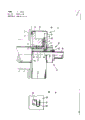
Fig. 1 is for being fixed on rotating speed signalling generator cut-away view on the driving shaft with fast fixture,
Fig. 2 is by rotating speed signalling generator elasticity anti-rotation device of the present invention,
Fig. 3 is the organization plan that rotating speed signalling generator is installed on axis by the present invention,
Fig. 4 is another kind of rotating speed signalling generator elasticity anti-rotation device.
The driving shaft 2 that stretches out from CD-ROM drive motor 1 is shaped on cylindrical step axle head 3, is shaped on threaded hole 4 at the center of axle head, and threaded hole has a big spot-facing 5 in driving shaft 2 ends.Adorned a rotating speed signalling generator 7 by hollow coupling shaft 6 on the axle head 3.
The hollow coupling shaft 6 that preferably adopts transition fit is parts of stepped hole 8, and stepped hole 8 passes a rotor 9 that is designed to the turning part and extends.Rotor 9 usefulness transition fit (being slidingly matched) are enclosed within on the step axle head 3, and lean against on the axle collar 10 with end face 36 thereafter.Rotor 9 is shaped on axle journal 11 towards that end of CD-ROM drive motor 1, and ball bearing 12 just is contained in above it.Towards motor that, rest on the collar 13 in the ball bearing 12, collar is placed in the axle journal 11 of the axle collar 10 fronts.
Adorned a stator 14 on ball bearing 12, it is as the support of a photoelectric scanning device, and photoelectric scanning device is made up of a transmitter 15 and a receiver 16, is fixed on code-wheel 19 on the rotor 9 from turning between them by locating ring 18.
Also fixed a signalling generator shell 25 that surrounds whole signalling generator on stator 14, there is a threaded hole 26 at its center.Invade in order to prevent dust and foul, can in threaded hole 26, insert a calotte 27, its the most handy rubber or plastics are made, and by means of one be articulated on the signalling generator shell 25 can rotating spring caps cover stent 28(spring base for example) prevent from reliably to come off.
Central authorities at rotating speed signalling generator 7 have adorned a fast fixture 17 divided into two parts, and it passes the tight screw 30 of speed that it stretches out by a spring holder 29 and one and is formed.The spring force of spring holder 29 is towards the end face of driving shaft 2.Adopting screw common on the market is relatively more suitable as the tight screw 30 of speed, and it enters by the threaded hole 26 of signalling generator shell 25, and screws in the threaded hole 4 of the normally ready-made and driving shaft 2 that need not specially process.Here look from head of screw, on the tight screw 30 of speed, spring holder 29 is housed successively, distance bush 31 and safety link 32.Spring holder 29 is designed to open up the springs that can contract, and it preferably is fixed on the convex shoulder in rotor 9 stepped holes 8 by reasonable structure form, and for example pointwise ground removes the flange crimping in hole above spring holder 29, or with methods such as spot welding, riveted joints.The length of distance bush 31 will be complementary with the length of driving shaft 2 step axle heads 3 and the width in rotating speed signalling generator 7 holes 8 exactly, and it also has a hole 33 in addition, and the internal diameter in hole 33 is slightly smaller than the external diameter of the safety link 32 that is contained in its back.Safety link 32 can adopt " 0 " shape circle general on the market, if then preferably adopt a steel loop without it.
Fast fixture 17 is preferably in manufacturing plant and just is assembled into the subassembly that can only just can take apart with instrument according to requirement of client and rotating speed signalling generator 7.In this case, safety link 32 and the stationary installation by the spring holder 29 of rational structure in rotor 9 prevent that together fast fixture 17 from coming off from rotating speed signalling generator 7.Certainly, can obtain same effect if assemble by user oneself, at this moment at first spring holder 29 is fixed in the rotor 9, then the tight screw 30 of speed is inserted by it, again the distance bush 31 that accurately matches is contained on the tight screw of speed, at last safety link 32 is inserted in the thread groove of the tight screw 30 of speed.
Before assembling rotating speed signalling generator 7, turn round calotte support 28 earlier, and from threaded hole 26, take off calotte 27.At this moment rotating speed signalling generator 7 was installed on the cylindrical step axle head 3 of driving shaft 2 in the past, and noted hole 23 that stopper pin 21 is aimed on the motor cases 22.After this, little by little screw the tight screw 30 of speed, the rotor 9 that has hollow coupling shaft 6 is moved on cylindrical step axle head 3, lean against on the axle collar 10 until its rear end face 36 with common nut wrench, and till when making in stopper pin 21 patchholes 23.
Under the state that the tight screw 30 of speed is tightened, safety link 32 is in spot-facing 5 zones of driving shaft 2 threaded holes 4, drives rotor 9 and does not only depend on friction to connect, and guarantees but also connect with rational structure by means of the stationary installation of rotor 9 upper spring dishes 29.Owing to the excessive situation that makes spring holder 29 be subjected to and excessively reverse of screw-down torque of the tight screw 30 of speed is actually and can not occurs, because can not producing plastic yield according to spring holder 29, the length of distance bush 31 do not determine, therefore irrelevant with the screw-down torque of the tight screw 30 of speed, it remains keeps the spring pressure that friction connects desired sensing driving shaft 2 directions.
When decomposing rotating speed signalling generator 7,, undertaken by desired each opposite working routine by unloading the tight screw 30 of speed simply.When making safety link 32 run into distance bush 31 after the tight screw 30 of speed changes some circles, safety link 32 has just become from the instrument of driving shaft 2 dismounting rotating speed signalling generators 7.When further outwards screwing out the tight screw 30 of speed, distance bush 31 is pressed to the spring holder 29 that is fixed in the rotor 9, and therefore impels rotating speed signalling generator 7 to decompose and pull out from cylinder step axle head 3.
Because no matter have only a unique procedure in assembling or when decomposing, so fairly simple and can not go wrong, these work can be undertaken by unskilled auxiliary worker under supervision at least.By the rotating speed signalling generator 7 accurate concentric structures that cooperate, and it is at the fixed clamping device of the absolute centering of driving shaft 2, so almost completely there is not concentricity, even also have no matter be slight error axial or radially, that is also absorbed and compensation by the gum sleeve 24 in hole 23 on the motor case 22.Rotating speed signalling generator 7 can fix to clamp with big screw-down torque on driving shaft 2, add stopper pin 21 is made fitting pin, match with corresponding mating holes 23 in the motor case 22, make reverse play be limited in a little scope like this, even so that for the pulse disc of precision encoding what remarkable influence it cause also can not for the displacement measurement of increment type again.
As seen from Figure 2, the rotation that prevents stator 14 is to realize by the elastic connecting device of another kind of form.Be fixed on 21 the pressure spring elements 34 in being fixed in motor case 22 of stopper pin on the stator 14.Each pressure spring element 34 has identical spring characteristic curve, the action direction of spring force points to the stopper pin 21 that is touched all the time, the sense of rotation of a pressure spring element 34 along driving shaft 2 wherein arranged, and another then is pressed on the stopper pin corresponding with it 21 against the sense of rotation of driving shaft 2.When axle does not change, these two pressure spring elements 34 less precompression of feeling better most.
Fig. 3 has represented by the present invention rotating speed signalling generator 7 to be installed in situation on the axis.The driving shaft 2 of CD-ROM drive motor 1 transfers axis 35 to through step, and thereby has formed an axle collar 10.Nestle up the rear end face 36 of rotor 9 in addition effectively.The hollow coupling shaft 6 of rotor 9 is different with the version among Fig. 1, makes cylindrical hole here, and is contained on the axis 35 to be slidingly matched.The structure of rotor 9 is identical with described in first example basically.On rotor, be contained in code-wheel 19 in an identical manner with a locating ring 18.In fact stator 14 has same structure with example described above, and it is bearing on the rotor 9 by two ball bearing 12.In this case, a side of ball bearing 12 is with a collar 13, and opposite side is by being fixed on bearing pressure ring 20 axial location on the stator 14.The core of whole rotating speed signalling generator 7 is covered by a signalling generator shell 25 that is fixedly connected with stator 14.By means of a taper dop 39,, rotor 9 is pressed vertically the axle collar 10 of past driving shaft 2 by stepped hold-down ring 38 and extensile spring holder 29.Taper dop 39 and spring holder 29 have constituted fast fixture 17.Want with it the rear end face 36 reliable Horizons of rotor 9 to be leaned against on the axle collar 10, then the taper dop should be passed towards motor direction on axis 35 before clamping vertically, touches the front end face 41 of rotor 9 until stepped hold-down ring 38.Once accomplished this point, just rotatable gland nut 40 is clamped on the axis 35 taper dop 39 firmly.Extensile spring holder 29 is compacted, makes it all impose enough big power radial and axial, so that the rear end face 36 of rotor 9 is abutted against on the axle collar 10 of driving shaft 2 effectively.Guaranteed that thus the rotor 9 that code-wheel 19 is housed does not have impact and is assemblied on the driving shaft 2 to error without spin.
Taper dop 39 as fast fixture 17 parts is a kind of parts that can buy on market, for example product of Tollok snap ring company.
In order to prevent stator 14 rotations, as shown in Figure 4, be provided with the flexural spring sheet 37 of " U " shape, it is riveted on the motor case 22 securely by the fixed head 42 of a bending.In " U " shape spring leaf 37, seamlessly insert the stopper pin 21 that is fixed on the stator 14.Fig. 3 has only represented an anti-rotation device.But can for example also install two.
Certainly the present invention is not limited only to the represented and version described in instructions among the figure, and they can only be as in the unrestricted example of the present invention.Self-evident, the mechanical component of diversified structural design pattern and particularly employing equivalence all belong to scope of the present invention.For example, can get on the bus at the driving shaft 2 of a perforation and make the groove of placement positioning ring, locating ring plays the axle collar 10.
Claims (11)
1, a kind of short structure rotating speed signalling generator, having is the hollow coupling shaft of its rotor part, it is contained on the driving shaft and can not relatively rotates each other, rotor is the support of code-disc of contracting, also have hollow coupling shaft is fixed on clamping part on the rotating driveshaft, in order to prevent the stator rotation of rotating speed signalling generator, stator and a retaining element link, it is characterized by: stator (14) can be bearing on the rotor (9) by bearing (12) with freely relatively rotating, described clamping part is a fast fixture (17), it has an anti-rotation spring holder (29) towards the axle collar (10) directive effect axle spring power, the clamping element of a concentric installation that can screw in vertically (30 or 39,40), version by friction is fixed on rotor (9) on the driving shaft (2), also be provided with a spacing element (31 or 38), it limits the decrement of spring holder (29) when tightening clamping element, and prevents that simultaneously it from producing plastic yield.
2, according to the described rotating speed signalling generator of claim 1, it is characterized by: in order to prevent stator (14) rotation, at stator (14) and fixed motor shell (22) however between be provided with two flexible hookups that enough corner rigidity are arranged that dispose along diameter at least.
3, according to the described rotating speed signalling generator of claim 2, it is characterized by: the elastic coupling device has the spring force that acts on the stopper pin (21) and the pressure spring element (34) of identical springs characteristic is formed by being fixed on the stopper pin (21) on the stator (14) and being fixed on the motor case (22), one of them pressure spring element (34) is along the sense of rotation of driving shaft (2), another pressure spring element (34) the then sense of rotation of contrary driving shaft (2) is pressed on the stopper pin corresponding with it (21), and these two pressure spring elements (34) should be subjected to less precompression when axle does not rotate.
4, according to the described rotating speed signalling generator of one of all claims in prostatitis, it is characterized by: the central authorities at signalling generator shell (25) open a threaded hole (26), and Kong Zhongke inserts the calotte (27) that an assurance can not be lost.
5, according to the described rotating speed signalling generator of one of prostatitis claim 1 to 3, it is characterized by: clamping element is designed to screw in one heart the tight screw (30) of speed of axle head (3).
6, according to the described rotating speed signalling generator of one of prostatitis claim 1 to 3, it is characterized by: clamping element be designed to axially movable, can be fixed on taper dop (39) on the axle by a gland nut of rotation (40).
7, according to the described rotating speed signalling generator of one of prostatitis claim 1 to 3, it is characterized by: can not lose by means of safety link (32) and the tight screw (30) of spring holder (29) assurance speed.
8, according to the described rotating speed signalling generator of claim 5, it is characterized by: can not lose by means of safety link (32) and the tight screw (30) of spring holder (29) assurance speed.
9, according to the described rotating speed signalling generator of claim 2, it is characterized by: the elastic coupling device seamlessly inserts the stopper pin (21) that is fixed on the stator by the flexural spring sheet (37) that is fixed on " U " shape on the motor case (22) with in spring leaf and forms.
10, according to the described rotating speed signalling generator of claim 2, it is characterized by: the elastic coupling device is by the hole (23) that is located on the motor case (22), the elastic insert (24) in hole (23) and be fixed on and adopt the stopper pin (21) that cooperates patchhole (23) to form on the stator.
11, according to the described rotating speed signalling generator of claim 1, it is characterized by: fast fixture imposes radially on rotor (9) and towards the device of the axle collar (10) directive effect clamping force for having.
Applications Claiming Priority (2)
| Application Number | Priority Date | Filing Date | Title |
|---|---|---|---|
| DE19853544751 DE3544751A1 (en) | 1985-12-18 | 1985-12-18 | TACHOGENERATOR |
| DEP3544751.6 | 1985-12-18 |
Publications (2)
| Publication Number | Publication Date |
|---|---|
| CN86108532A CN86108532A (en) | 1987-08-26 |
| CN1004105B true CN1004105B (en) | 1989-05-03 |
Family
ID=6288743
Family Applications (1)
| Application Number | Title | Priority Date | Filing Date |
|---|---|---|---|
| CN86108532.9A Expired CN1004105B (en) | 1985-12-18 | 1986-12-17 | Rotating speed signal transmitter |
Country Status (9)
| Country | Link |
|---|---|
| US (1) | US4759218A (en) |
| EP (1) | EP0226828B1 (en) |
| JP (2) | JPS62162966A (en) |
| CN (1) | CN1004105B (en) |
| AT (1) | ATE67605T1 (en) |
| CA (1) | CA1289381C (en) |
| DE (2) | DE3544751A1 (en) |
| DK (1) | DK166973B1 (en) |
| NO (1) | NO167829C (en) |
Families Citing this family (22)
| Publication number | Priority date | Publication date | Assignee | Title |
|---|---|---|---|---|
| DE3717180A1 (en) * | 1987-05-22 | 1988-12-08 | Licentia Gmbh | ELECTRIC MOTOR WITH ATTACHED TACHOGENERATOR |
| DE3908932A1 (en) * | 1988-05-25 | 1989-12-07 | Heidenhain Gmbh Dr Johannes | ANGLE MEASURING DEVICE |
| DE3942826C3 (en) * | 1989-12-23 | 1994-07-14 | T & R Electronic Gmbh | Housing suspension for a measuring device for rotary movements |
| DE4213979A1 (en) * | 1992-04-29 | 1993-11-04 | Teves Metallwaren Alfred | DEVICE FOR MEASURING ROTATIONAL MOTIONS |
| US5495758A (en) * | 1993-06-17 | 1996-03-05 | Lake Shore Cryotronics, Inc. | Tachometer assembly with integral internal wrench |
| DE4322744C2 (en) † | 1993-07-08 | 1998-08-27 | Baumueller Nuernberg Gmbh | Electrical drive system and positioning method for the synchronous adjustment of several rotatable and / or pivotable functional parts in devices and machines, drive arrangement with an angular position encoder and printing machine |
| DE4324622A1 (en) * | 1993-07-22 | 1995-01-26 | Teves Gmbh Alfred | Device for detecting the rotary movement |
| DE9315994U1 (en) * | 1993-10-20 | 1994-02-24 | Stroeter Antriebstech Gmbh | Flange motor with measuring device to record the rotation of the motor shaft |
| US5981940A (en) | 1997-09-15 | 1999-11-09 | Renco Encoders, Inc. | Angle measuring system with a clampable shaft |
| US6642508B2 (en) * | 2001-08-31 | 2003-11-04 | Renco Encoders, Inc. | System and method in an angle measuring system with an encoder attachment system for attaching an encoder to a motor shaft through the use of a spring generating a radial pressure |
| DE50200576D1 (en) † | 2002-02-21 | 2004-08-05 | Reifenhaeuser Masch | smoothing device |
| US7109616B2 (en) * | 2003-10-16 | 2006-09-19 | Fasco Industries, Inc. | Electric motor with hall effect memory module |
| DE102005014808B4 (en) * | 2005-03-31 | 2009-11-26 | Siemens Ag | measuring device |
| DE202005006379U1 (en) * | 2005-04-21 | 2006-08-24 | Hengstler Gmbh | Hollow shaft encoder with motor shaft protection cap |
| WO2007065496A1 (en) | 2005-12-11 | 2007-06-14 | Valeo Schalter Und Sensoren Gmbh | Rotation angle sensor and rotation angle sensor system |
| DE102005060519A1 (en) * | 2005-12-11 | 2007-06-14 | Valeo Schalter Und Sensoren Gmbh | Rotation angle sensor for use in motor vehicle, has signal transducer which is arranged on shaft mount, housing fastened to shaft end by shaft mount, and signal receiver arranged on housing and interacting with transducer |
| DE102010035773A1 (en) * | 2010-08-26 | 2012-03-01 | Dunkermotoren Gmbh | Electric motor and method for its production |
| DE102010062480A1 (en) * | 2010-12-06 | 2012-06-06 | Aktiebolaget Skf | Rolling bearing assembly used in gearbox of engine, has rotary encoder and code transducer that are accommodated within transmitter housings comprising rotatably mounted coding unit coupled with shaft |
| CN103276525B (en) * | 2013-06-08 | 2015-03-04 | 福建睿能科技股份有限公司 | Computerized flat knitting machine and code disc assembly |
| CN106841653A (en) * | 2017-03-29 | 2017-06-13 | 湖南湘依铁路机车电器股份有限公司 | A kind of locomotive tach signal shaft end output intent and device |
| DE102017117759A1 (en) * | 2017-08-04 | 2019-02-07 | Mimatic Gmbh | Sensor retrofit kit |
| CN112605676A (en) * | 2020-12-25 | 2021-04-06 | 南京宁庆数控机床制造有限公司 | Automatic clamping mechanism for cutter and operation method thereof |
Family Cites Families (19)
| Publication number | Priority date | Publication date | Assignee | Title |
|---|---|---|---|---|
| US1320259A (en) * | 1919-10-28 | Ebanz mabtens | ||
| US1641059A (en) * | 1925-05-19 | 1927-08-30 | Tausch Ernst | Resilient-ring element |
| DE1016966B (en) * | 1956-01-11 | 1957-10-03 | Max Wuppermann Dipl Ing | Attachment for tachometer or the like. |
| US3012744A (en) * | 1957-07-18 | 1961-12-12 | Waters Mfg Inc | Mounting device |
| DE1106854B (en) * | 1960-03-16 | 1961-05-18 | Licentia Gmbh | Auxiliary electrical generator |
| DE1221058B (en) * | 1961-09-14 | 1966-07-14 | Oskar E Peter | Attachment of a hub to a shaft end or shaft shoulder |
| DE6604776U (en) * | 1961-10-28 | 1970-02-26 | Johannes Huebner Fabrik Elek S | DC OR AC TACHOMETER DYNAMO. |
| NL11261C (en) * | 1965-05-04 | |||
| US3687184A (en) * | 1969-12-30 | 1972-08-29 | Illinois Tool Works | Fastener unit |
| US3693024A (en) * | 1971-05-17 | 1972-09-19 | Litton Systems Inc | Rotational shaft encoder having a bearing tube having a slot therein |
| DE2416113C2 (en) * | 1974-04-03 | 1984-09-27 | Quick-Rotan Becker & Notz Kg, 6100 Darmstadt | Actual value encoder for speed-controlled drives |
| US3995156A (en) * | 1975-03-25 | 1976-11-30 | Quick-Rotan Becker & Notz Kg | Transmitter for governed-speed drives employing an optical grating and photocells at an angle thereto |
| US4193199A (en) * | 1978-05-15 | 1980-03-18 | Servo Products Company | Shaft position transducer |
| JPS60513B2 (en) * | 1978-06-16 | 1985-01-08 | 株式会社塚田工業 | tiered metal roof |
| DE2921103C2 (en) * | 1979-05-25 | 1986-09-25 | Robert Bosch Gmbh, 7000 Stuttgart | Incremental rotary encoder |
| DE3017193A1 (en) * | 1980-05-05 | 1981-11-12 | Siemens AG, 1000 Berlin und 8000 München | BUILT-IN ARMATURE FOR MEASURING VALVES AT HARD ACCESSIBLE MEASURING POINTS IN MACHINES |
| DE3038005A1 (en) * | 1980-10-08 | 1982-05-06 | Zinser Textilmaschinen Gmbh, 7333 Ebersbach | Rotating machine with built-in tachometer - eliminates unwanted axial and radial motion between stator and rotor |
| IT1129862B (en) * | 1980-11-17 | 1986-06-11 | Olivetti & Co Spa | OPTICAL TRANSDUCER |
| DE3301205C2 (en) * | 1982-02-26 | 1985-10-03 | Dr. Johannes Heidenhain Gmbh, 8225 Traunreut | Angle measuring device |
-
1985
- 1985-12-18 DE DE19853544751 patent/DE3544751A1/en active Granted
-
1986
- 1986-11-06 CA CA000522395A patent/CA1289381C/en not_active Expired - Lifetime
- 1986-11-19 DK DK553286A patent/DK166973B1/en not_active IP Right Cessation
- 1986-11-20 DE DE8686116100T patent/DE3681568D1/en not_active Expired - Lifetime
- 1986-11-20 AT AT86116100T patent/ATE67605T1/en not_active IP Right Cessation
- 1986-11-20 EP EP86116100A patent/EP0226828B1/en not_active Expired - Lifetime
- 1986-12-17 CN CN86108532.9A patent/CN1004105B/en not_active Expired
- 1986-12-17 NO NO865119A patent/NO167829C/en unknown
- 1986-12-18 US US06/943,925 patent/US4759218A/en not_active Expired - Fee Related
- 1986-12-18 JP JP61300205A patent/JPS62162966A/en active Pending
-
1995
- 1995-01-10 JP JP000036U patent/JPH0743686U/en active Pending
Also Published As
| Publication number | Publication date |
|---|---|
| NO865119L (en) | 1987-06-19 |
| EP0226828A2 (en) | 1987-07-01 |
| DE3681568D1 (en) | 1991-10-24 |
| NO167829C (en) | 1991-12-11 |
| DE3544751A1 (en) | 1987-06-19 |
| DE3544751C2 (en) | 1991-07-18 |
| CN86108532A (en) | 1987-08-26 |
| US4759218A (en) | 1988-07-26 |
| CA1289381C (en) | 1991-09-24 |
| NO865119D0 (en) | 1986-12-17 |
| EP0226828B1 (en) | 1991-09-18 |
| DK553286A (en) | 1987-06-19 |
| NO167829B (en) | 1991-09-02 |
| DK166973B1 (en) | 1993-08-09 |
| DK553286D0 (en) | 1986-11-19 |
| JPS62162966A (en) | 1987-07-18 |
| JPH0743686U (en) | 1995-09-05 |
| ATE67605T1 (en) | 1991-10-15 |
| EP0226828A3 (en) | 1989-07-19 |
Similar Documents
| Publication | Publication Date | Title |
|---|---|---|
| CN1004105B (en) | Rotating speed signal transmitter | |
| US7546689B2 (en) | Joint for coordinate measurement device | |
| US4485682A (en) | Transducer for torque and/or angular displacement measurement, especially in power screwdrivers | |
| CN113607100B (en) | Ultralight and ultraaccurate portable coordinate measuring machine | |
| US20030196497A1 (en) | Torque measuring device | |
| US3813933A (en) | Dynamic torque indicators | |
| GB2225430A (en) | Surface roughness measuring instrument | |
| US6799480B1 (en) | Screwdriver with torque measuring scale and method of making same | |
| CA1052124A (en) | Torque analyzing apparatus | |
| CN211824253U (en) | Angular displacement sensor calibration system | |
| CN101027534B (en) | Micrometer comprising a non-rotative spindle | |
| US10634478B2 (en) | Ultra-light and ultra-accurate portable coordinate measurement machine with serial bus capture | |
| WO2023225301A1 (en) | Ultra-light and ultra-accurate portable coordinate measurement machine with reduced profile swivel joints | |
| CN111300328A (en) | Torsion adjusting device | |
| CN208104729U (en) | A kind of integral type synchronous belt wheel device and its mounting structure | |
| CN114715323B (en) | Bicycle crank power meter capable of measuring force direction and position | |
| CN109616827B (en) | Joint screwing device | |
| CN118817128B (en) | Pressure indicator for building support equipment | |
| RU2112639C1 (en) | Apparatus for tuning nut wrenches | |
| SU1317266A1 (en) | Appliance for calibrating electric torsiograph | |
| JPS634130B2 (en) | ||
| EP1122029A3 (en) | High precision multi-discs grinding module and method for manufacturing the same | |
| KR100501500B1 (en) | Length guage dispatch tool | |
| JP2509166Y2 (en) | Ball center position measuring device of differential case | |
| SU1453158A1 (en) | Device for calibrating strain-measuring devices |
Legal Events
| Date | Code | Title | Description |
|---|---|---|---|
| C10 | Entry into substantive examination | ||
| SE01 | Entry into force of request for substantive examination | ||
| C06 | Publication | ||
| PB01 | Publication | ||
| C13 | Decision | ||
| GR02 | Examined patent application | ||
| C14 | Grant of patent or utility model | ||
| GR01 | Patent grant | ||
| C19 | Lapse of patent right due to non-payment of the annual fee | ||
| CF01 | Termination of patent right due to non-payment of annual fee |