EP0226190B1 - Dispositif d'étanchéité - Google Patents
Dispositif d'étanchéité Download PDFInfo
- Publication number
- EP0226190B1 EP0226190B1 EP86117320A EP86117320A EP0226190B1 EP 0226190 B1 EP0226190 B1 EP 0226190B1 EP 86117320 A EP86117320 A EP 86117320A EP 86117320 A EP86117320 A EP 86117320A EP 0226190 B1 EP0226190 B1 EP 0226190B1
- Authority
- EP
- European Patent Office
- Prior art keywords
- jacket
- accordance
- insulating material
- conduit
- half shells
- Prior art date
- Legal status (The legal status is an assumption and is not a legal conclusion. Google has not performed a legal analysis and makes no representation as to the accuracy of the status listed.)
- Expired
Links
Images

Classifications
-
- F—MECHANICAL ENGINEERING; LIGHTING; HEATING; WEAPONS; BLASTING
- F16—ENGINEERING ELEMENTS AND UNITS; GENERAL MEASURES FOR PRODUCING AND MAINTAINING EFFECTIVE FUNCTIONING OF MACHINES OR INSTALLATIONS; THERMAL INSULATION IN GENERAL
- F16L—PIPES; JOINTS OR FITTINGS FOR PIPES; SUPPORTS FOR PIPES, CABLES OR PROTECTIVE TUBING; MEANS FOR THERMAL INSULATION IN GENERAL
- F16L5/00—Devices for use where pipes, cables or protective tubing pass through walls or partitions
- F16L5/02—Sealing
- F16L5/04—Sealing to form a firebreak device
-
- F—MECHANICAL ENGINEERING; LIGHTING; HEATING; WEAPONS; BLASTING
- F16—ENGINEERING ELEMENTS AND UNITS; GENERAL MEASURES FOR PRODUCING AND MAINTAINING EFFECTIVE FUNCTIONING OF MACHINES OR INSTALLATIONS; THERMAL INSULATION IN GENERAL
- F16L—PIPES; JOINTS OR FITTINGS FOR PIPES; SUPPORTS FOR PIPES, CABLES OR PROTECTIVE TUBING; MEANS FOR THERMAL INSULATION IN GENERAL
- F16L59/00—Thermal insulation in general
- F16L59/14—Arrangements for the insulation of pipes or pipe systems
- F16L59/145—Arrangements for the insulation of pipes or pipe systems providing fire-resistance
Definitions
- the invention relates to an apparatus for fire-f and most smoke-tight sealing of passages insulated conduits through walls and ceilings, wherein the the respective tube enclosing insulating material in the region of the wall or ceiling passage is surrounded by a mechanically rigid, in particular metal casing and the axial length of the jacket is at least substantially the same or slightly larger than the thickness of the respective wall or ceiling through which the pipe extends.
- a device of this type is known from US-A 4 086 736.
- the space between the pipe, which in this case is not insulated, and the jacket is filled with insulating material in the form of silicone foam or ceramic fibers, and a closure flap which can be clamped in place is attached to both ends of the jacket at the end of this bushing area.
- the object of the invention is to provide a device of the type mentioned, which is easy to assemble, has a variety of uses and is characterized by high effectiveness and reliability in the event of a fire.
- This object is essentially achieved in that at least one circumferentially distributed layer of sealing material that expands when exposed to heat is provided between the jacket and the pipe, and the radial thickness of the expandable layer is only a fraction of the insulating material.
- the sealing material expands to a multiple of its original thickness, whereby this material has plastic properties during the expansion process and can therefore spread in all directions, so that excellent seals are achieved.
- vermicular graphite is used as an expandable active ingredient.
- the material is insensitive to water, atmospheric agents, chemicals and solvents, which ensures an absolutely tight seal in the event of a fire.
- suitable dimensioning it can also be achieved that the expanding material exerts such high forces in the radial direction that the respective line, in particular a plastic line, is compressed and thus also closed.
- the sealing material After being inflated by the action of heat, the sealing material is in the form of a thermally stable, heat-resistant foam layer with a low thermal conductivity.
- an expandable layer of the sealing material is provided between the jacket and the insulating material, but according to preferred embodiments, a corresponding expandable layer is additionally arranged between the pipe and the insulating material, so that a particularly rapid effectiveness can be achieved in this way, utilizing the heat transfer properties of the pipe and the outer covering .
- At least one flat heat conductor which extends over the length of the jacket, is arranged inside the jacket, which in turn serves to transport the thermal energy required to trigger the blowing process as quickly as possible into the pipe passage area and to initiate the blowing process there, but without the insulation properties in the normal case to influence.
- the jacket of the device according to the invention is preferably designed in the form of two half-shells which can be connected to one another, the half-shells being able to be coupled in the region of their longitudinal edges in such a way that radially acting forces can be reliably absorbed.
- the half-shells can preferably be non-positively coupled by means of a shape engagement, but it is also possible to provide corresponding screw connections at least on one side.
- Fig. 1 shows a pipe, for example made of metal, which ver according to existing regulations with, for example, an insulation consisting of closed-cell foam 2 see is.
- the insulation 2 is enclosed by a jacket 4, which is mechanically fixed and consists, for example, of metal.
- This arrangement is guided through a bushing 3 in a wall 7.
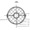
- FIG. 2 a cross-sectional view of an embodiment variant is shown, in which a first layer 5 of sealing material that expands when exposed to heat is arranged between the metallic jacket 4 and the insulating material 2, and a second layer 6 of itself in the event of heat inflating sealing material between the pipe 1 and the insulating material 2 is provided.
- the jacket 4 is designed in the form of half-shells which are connected to one another via a joint 8 and on the other hand are mutually fixed in an overlap area by means of radially extending screws 9.
- flange connections and snap-snap connections between the half-shells are preferably used, which ensure and ensure a non-positive connection, so that forces acting radially on the casing 4 can be absorbed well.
- both layers of material 5, 6 inflate very quickly and at least close the passage area between pipe 1 and jacket 4, but according to special embodiments, the arrangement is chosen so that the inflation pressure is sufficient to also the pipe in the presence of plastic pipes 1 squeeze and seal yourself. The necessary back pressure is absorbed by the jacket.
Claims (11)
Priority Applications (1)
| Application Number | Priority Date | Filing Date | Title |
|---|---|---|---|
| AT86117320T ATE46567T1 (de) | 1985-12-13 | 1986-12-12 | Abschottungsvorrichtung. |
Applications Claiming Priority (2)
| Application Number | Priority Date | Filing Date | Title |
|---|---|---|---|
| DE19853544129 DE3544129A1 (de) | 1985-12-13 | 1985-12-13 | Abschottungsvorrichtung |
| DE3544129 | 1985-12-13 |
Publications (2)
| Publication Number | Publication Date |
|---|---|
| EP0226190A1 EP0226190A1 (fr) | 1987-06-24 |
| EP0226190B1 true EP0226190B1 (fr) | 1989-09-20 |
Family
ID=6288383
Family Applications (1)
| Application Number | Title | Priority Date | Filing Date |
|---|---|---|---|
| EP86117320A Expired EP0226190B1 (fr) | 1985-12-13 | 1986-12-12 | Dispositif d'étanchéité |
Country Status (3)
| Country | Link |
|---|---|
| EP (1) | EP0226190B1 (fr) |
| AT (1) | ATE46567T1 (fr) |
| DE (2) | DE3544129A1 (fr) |
Cited By (5)
| Publication number | Priority date | Publication date | Assignee | Title |
|---|---|---|---|---|
| DE3930722A1 (de) * | 1989-09-14 | 1991-03-28 | Gruenau Gmbh Chem Fab | Rohrschott |
| DE4113375A1 (de) * | 1990-04-24 | 1991-10-31 | Furukawa Electric Co Ltd | Anordnung zum feuergeschuetzten durchleiten eines kanals durch eine brandschutzwand |
| DE10227098A1 (de) * | 2002-06-18 | 2004-01-08 | Schulte, Günter | Einrichtung für die feuer- und/oder rauchsichere Durchführung insbesondere von Kabeln |
| DE10305903A1 (de) * | 2003-02-13 | 2004-08-26 | Schulte, Günter | Brandschutzvorrichtung für eine durch eine Wand oder Decke durchgeführte Rohrleitung |
| DE19934902B4 (de) * | 1998-07-22 | 2009-06-18 | Uba Tec Umweltgerechte Brandschutz- Und Akustikprodukte Gmbh | Abschottung zur feuerbeständigen, rauchdichten Durchführung von Rohren, Kabeln und Kanälen oder anderen Bauteilen durch Wände oder Decken |
Families Citing this family (6)
| Publication number | Priority date | Publication date | Assignee | Title |
|---|---|---|---|---|
| GB9013533D0 (en) * | 1990-06-18 | 1990-08-08 | Dufaylite Dev Ltd | Apparatus for the prevention of spread of fire |
| DE4131147C1 (fr) * | 1991-09-19 | 1992-11-19 | Werner 7925 Dischingen De Hauff | |
| GB2419385B (en) * | 2004-10-22 | 2010-01-13 | Saint Gobain Pipelines Plc | Improvements in or relating to pipework assemblies |
| CN102927375B (zh) * | 2012-10-31 | 2015-06-17 | 北京国电清新环保技术股份有限公司 | 伞盖式封料装置 |
| EP3792420A4 (fr) * | 2019-07-30 | 2021-07-07 | Jung Un Kim | Structure ignifuge pour coupe-feu traversant de bâtiment |
| GB2621565A (en) * | 2022-08-11 | 2024-02-21 | Intumescent Systems Ltd | Fire protective sleeve |
Family Cites Families (9)
| Publication number | Priority date | Publication date | Assignee | Title |
|---|---|---|---|---|
| DE2632325C3 (de) * | 1976-07-17 | 1983-12-29 | Neuwalzwerk Bettermann Ohg, 5750 Menden | Brandschutzeinrichtung für eine Kabeldurchführung |
| US4086736A (en) * | 1976-12-16 | 1978-05-02 | Daniel International Corporation | Fire and liquid seals for pipes and conduits and method of forming same |
| CH636667A5 (en) * | 1978-12-28 | 1983-06-15 | Geberit Ag | Fire-extinguishing passage through walls or floors for flammable pipelines and cables |
| US4424867A (en) * | 1981-03-31 | 1984-01-10 | Fiberglas Canada Inc. | Heat hardening sealant-gel for flexible couplings |
| GB2108614B (en) * | 1981-07-23 | 1985-01-03 | Dixon International Ltd | Fire-seal for pipe or duct extending through wall floor or ceiling |
| GB2111624A (en) * | 1981-12-14 | 1983-07-06 | Mann Mcgowan Fabrications Limi | Fire-resistant sleeve |
| DE3246910A1 (de) * | 1982-12-18 | 1984-06-20 | Kaefer Isoliertechnik Gmbh & Co Kg, 2800 Bremen | Durchfuehrung fuer strahlenbelastete waende |
| DK110184A (da) * | 1984-02-27 | 1985-08-28 | Armadan Isolering As | Fremgangsmaade til isolering af roer eller lignende ved gennemfoeringer, samt gennemfoeringsboesning til brug ved udoevelse af fremgangsmaaden |
| DE3435658C2 (de) * | 1984-09-28 | 1986-01-16 | FW-Fernwärme-Technik GmbH, 3004 Isernhagen | Durchführung für ein Rohr |
-
1985
- 1985-12-13 DE DE19853544129 patent/DE3544129A1/de not_active Ceased
-
1986
- 1986-12-12 EP EP86117320A patent/EP0226190B1/fr not_active Expired
- 1986-12-12 DE DE8686117320T patent/DE3665760D1/de not_active Expired
- 1986-12-12 AT AT86117320T patent/ATE46567T1/de not_active IP Right Cessation
Cited By (5)
| Publication number | Priority date | Publication date | Assignee | Title |
|---|---|---|---|---|
| DE3930722A1 (de) * | 1989-09-14 | 1991-03-28 | Gruenau Gmbh Chem Fab | Rohrschott |
| DE4113375A1 (de) * | 1990-04-24 | 1991-10-31 | Furukawa Electric Co Ltd | Anordnung zum feuergeschuetzten durchleiten eines kanals durch eine brandschutzwand |
| DE19934902B4 (de) * | 1998-07-22 | 2009-06-18 | Uba Tec Umweltgerechte Brandschutz- Und Akustikprodukte Gmbh | Abschottung zur feuerbeständigen, rauchdichten Durchführung von Rohren, Kabeln und Kanälen oder anderen Bauteilen durch Wände oder Decken |
| DE10227098A1 (de) * | 2002-06-18 | 2004-01-08 | Schulte, Günter | Einrichtung für die feuer- und/oder rauchsichere Durchführung insbesondere von Kabeln |
| DE10305903A1 (de) * | 2003-02-13 | 2004-08-26 | Schulte, Günter | Brandschutzvorrichtung für eine durch eine Wand oder Decke durchgeführte Rohrleitung |
Also Published As
| Publication number | Publication date |
|---|---|
| EP0226190A1 (fr) | 1987-06-24 |
| DE3544129A1 (de) | 1987-06-19 |
| ATE46567T1 (de) | 1989-10-15 |
| DE3665760D1 (en) | 1989-10-26 |
Similar Documents
| Publication | Publication Date | Title |
|---|---|---|
| EP0226190B1 (fr) | Dispositif d'étanchéité | |
| DE19600369C2 (de) | Brandschutzeinrichtung zur Abschottung einer Rohrleitung | |
| DE2947652A1 (de) | Feuerhemmende abschottung fuer durchfuehrungen von rohrleitungen aus kunststoff | |
| AT391931B (de) | Brandabschlussmanschette | |
| EP0869303A3 (fr) | Dispositif pour boucher une ouverture de traversée de câble | |
| DE2503022A1 (de) | Vorrichtung mit feuerschutzverschlussklappe oder mit rauchabzugklappe | |
| EP0349881B1 (fr) | Manchon pare-feu | |
| EP2535627B1 (fr) | Dispositif de protection anti-incendie | |
| DE2907473A1 (de) | Elektrisches kabel | |
| DE19617017A1 (de) | Vorrichtung zum Verschließen von Wandöffnungen, Rohren o. dgl. Strömungsquerschnitten und im Brandfall expandierende Masse | |
| DE2824370A1 (de) | Flammschutz fuer elektrische anlagen | |
| DE2713689A1 (de) | Feuerhemmende vorrichtung fuer waende durchsetzende rohre und feuerhemmende anordnung | |
| DE3541442C2 (fr) | ||
| DE19649749A1 (de) | Verfahren zur Ausbildung eines Brandschutzes für brennbare oder hitzegefährdete Bauteile | |
| EP0362929A1 (fr) | Câble de communication résistant au feu | |
| DE3728055C2 (de) | Kombinations-Schutzraum | |
| EP3768393A1 (fr) | Dispositif de protection contre l'incendie ainsi que module de protection contre l'incendie | |
| EP1512434A1 (fr) | dispositif coupe-feu pour tuyauterie traversant une paroi | |
| DE19938498A1 (de) | Brandschutz-Absperrung für eine lufttechnische Anlage eines Gebäudes mit zumindestens einem einen Luftstrom führenden Lüftungskanal | |
| DE4139375A1 (de) | Vorrichtung zum abschotten eines durch eine wand hindurchgefuehrten kunststoffrohres im brandfall | |
| DE102004055928B4 (de) | Brandschutzmanschette | |
| DE3420937A1 (de) | Injektionsrohr zum injizieren von dampf in den boden | |
| DE10305903A1 (de) | Brandschutzvorrichtung für eine durch eine Wand oder Decke durchgeführte Rohrleitung | |
| DE19634305B4 (de) | Wartungsfreie Vorrichtung zur rauch- und brandsicheren Abschottung einer Lüftungsrohrleitung | |
| DE3316425A1 (de) | Brandschutzeinrichtung fuer rohrleitungen |
Legal Events
| Date | Code | Title | Description |
|---|---|---|---|
| PUAI | Public reference made under article 153(3) epc to a published international application that has entered the european phase |
Free format text: ORIGINAL CODE: 0009012 |
|
| AK | Designated contracting states |
Kind code of ref document: A1 Designated state(s): AT BE CH DE FR IT LI LU NL |
|
| 17P | Request for examination filed |
Effective date: 19870714 |
|
| 17Q | First examination report despatched |
Effective date: 19871210 |
|
| GRAA | (expected) grant |
Free format text: ORIGINAL CODE: 0009210 |
|
| AK | Designated contracting states |
Kind code of ref document: B1 Designated state(s): AT BE CH DE FR IT LI LU NL |
|
| REF | Corresponds to: |
Ref document number: 46567 Country of ref document: AT Date of ref document: 19891015 Kind code of ref document: T |
|
| ITF | It: translation for a ep patent filed |
Owner name: BARZANO' E ZANARDO MILANO S.P.A. |
|
| REF | Corresponds to: |
Ref document number: 3665760 Country of ref document: DE Date of ref document: 19891026 |
|
| ET | Fr: translation filed | ||
| PLBE | No opposition filed within time limit |
Free format text: ORIGINAL CODE: 0009261 |
|
| STAA | Information on the status of an ep patent application or granted ep patent |
Free format text: STATUS: NO OPPOSITION FILED WITHIN TIME LIMIT |
|
| 26N | No opposition filed | ||
| ITTA | It: last paid annual fee | ||
| EPTA | Lu: last paid annual fee | ||
| PGFP | Annual fee paid to national office [announced via postgrant information from national office to epo] |
Ref country code: NL Payment date: 20031217 Year of fee payment: 18 |
|
| PGFP | Annual fee paid to national office [announced via postgrant information from national office to epo] |
Ref country code: FR Payment date: 20031218 Year of fee payment: 18 |
|
| PGFP | Annual fee paid to national office [announced via postgrant information from national office to epo] |
Ref country code: CH Payment date: 20031224 Year of fee payment: 18 |
|
| PGFP | Annual fee paid to national office [announced via postgrant information from national office to epo] |
Ref country code: LU Payment date: 20031230 Year of fee payment: 18 |
|
| PGFP | Annual fee paid to national office [announced via postgrant information from national office to epo] |
Ref country code: BE Payment date: 20031231 Year of fee payment: 18 |
|
| PG25 | Lapsed in a contracting state [announced via postgrant information from national office to epo] |
Ref country code: LU Free format text: LAPSE BECAUSE OF NON-PAYMENT OF DUE FEES Effective date: 20041212 |
|
| PGFP | Annual fee paid to national office [announced via postgrant information from national office to epo] |
Ref country code: AT Payment date: 20041213 Year of fee payment: 19 |
|
| PG25 | Lapsed in a contracting state [announced via postgrant information from national office to epo] |
Ref country code: LI Free format text: LAPSE BECAUSE OF NON-PAYMENT OF DUE FEES Effective date: 20041231 Ref country code: CH Free format text: LAPSE BECAUSE OF NON-PAYMENT OF DUE FEES Effective date: 20041231 Ref country code: BE Free format text: LAPSE BECAUSE OF NON-PAYMENT OF DUE FEES Effective date: 20041231 |
|
| PGFP | Annual fee paid to national office [announced via postgrant information from national office to epo] |
Ref country code: DE Payment date: 20050225 Year of fee payment: 19 |
|
| BERE | Be: lapsed |
Owner name: E. *MISSEL G.M.B.H. & CO. Effective date: 20041231 |
|
| PG25 | Lapsed in a contracting state [announced via postgrant information from national office to epo] |
Ref country code: NL Free format text: LAPSE BECAUSE OF NON-PAYMENT OF DUE FEES Effective date: 20050701 |
|
| REG | Reference to a national code |
Ref country code: CH Ref legal event code: PL |
|
| PG25 | Lapsed in a contracting state [announced via postgrant information from national office to epo] |
Ref country code: FR Free format text: LAPSE BECAUSE OF NON-PAYMENT OF DUE FEES Effective date: 20050831 |
|
| NLV4 | Nl: lapsed or anulled due to non-payment of the annual fee |
Effective date: 20050701 |
|
| REG | Reference to a national code |
Ref country code: FR Ref legal event code: ST |
|
| PG25 | Lapsed in a contracting state [announced via postgrant information from national office to epo] |
Ref country code: IT Free format text: LAPSE BECAUSE OF NON-PAYMENT OF DUE FEES;WARNING: LAPSES OF ITALIAN PATENTS WITH EFFECTIVE DATE BEFORE 2007 MAY HAVE OCCURRED AT ANY TIME BEFORE 2007. THE CORRECT EFFECTIVE DATE MAY BE DIFFERENT FROM THE ONE RECORDED. Effective date: 20051212 Ref country code: AT Free format text: LAPSE BECAUSE OF NON-PAYMENT OF DUE FEES Effective date: 20051212 |
|
| PG25 | Lapsed in a contracting state [announced via postgrant information from national office to epo] |
Ref country code: DE Free format text: LAPSE BECAUSE OF NON-PAYMENT OF DUE FEES Effective date: 20060701 |
|
| BERE | Be: lapsed |
Owner name: E. *MISSEL G.M.B.H. & CO. Effective date: 20041231 |