EP0225766A2 - Réceptacle à disques - Google Patents
Réceptacle à disques Download PDFInfo
- Publication number
- EP0225766A2 EP0225766A2 EP86309232A EP86309232A EP0225766A2 EP 0225766 A2 EP0225766 A2 EP 0225766A2 EP 86309232 A EP86309232 A EP 86309232A EP 86309232 A EP86309232 A EP 86309232A EP 0225766 A2 EP0225766 A2 EP 0225766A2
- Authority
- EP
- European Patent Office
- Prior art keywords
- disk
- slide
- disk cartridge
- disks
- storage
- Prior art date
- Legal status (The legal status is an assumption and is not a legal conclusion. Google has not performed a legal analysis and makes no representation as to the accuracy of the status listed.)
- Granted
Links
- 238000001514 detection method Methods 0.000 claims description 17
- 238000007599 discharging Methods 0.000 claims description 5
- 238000005192 partition Methods 0.000 claims description 5
- 230000037431 insertion Effects 0.000 description 8
- 238000003780 insertion Methods 0.000 description 8
- 230000001133 acceleration Effects 0.000 description 2
- 230000002093 peripheral effect Effects 0.000 description 2
- 230000003247 decreasing effect Effects 0.000 description 1
Images


Classifications
-
- G—PHYSICS
- G11—INFORMATION STORAGE
- G11B—INFORMATION STORAGE BASED ON RELATIVE MOVEMENT BETWEEN RECORD CARRIER AND TRANSDUCER
- G11B17/00—Guiding record carriers not specifically of filamentary or web form, or of supports therefor
- G11B17/02—Details
- G11B17/038—Centering or locking of a plurality of discs in a single cartridge
-
- G—PHYSICS
- G11—INFORMATION STORAGE
- G11B—INFORMATION STORAGE BASED ON RELATIVE MOVEMENT BETWEEN RECORD CARRIER AND TRANSDUCER
- G11B17/00—Guiding record carriers not specifically of filamentary or web form, or of supports therefor
- G11B17/22—Guiding record carriers not specifically of filamentary or web form, or of supports therefor from random access magazine of disc records
- G11B17/225—Guiding record carriers not specifically of filamentary or web form, or of supports therefor from random access magazine of disc records wherein the disks are transferred from a fixed magazine to a fixed playing unit using a moving carriage
-
- G—PHYSICS
- G11—INFORMATION STORAGE
- G11B—INFORMATION STORAGE BASED ON RELATIVE MOVEMENT BETWEEN RECORD CARRIER AND TRANSDUCER
- G11B23/00—Record carriers not specific to the method of recording or reproducing; Accessories, e.g. containers, specially adapted for co-operation with the recording or reproducing apparatus ; Intermediate mediums; Apparatus or processes specially adapted for their manufacture
- G11B23/02—Containers; Storing means both adapted to cooperate with the recording or reproducing means
- G11B23/03—Containers for flat record carriers
- G11B23/032—Containers for flat record carriers for rigid discs
- G11B23/0323—Containers for flat record carriers for rigid discs for disc-packs
-
- G—PHYSICS
- G11—INFORMATION STORAGE
- G11B—INFORMATION STORAGE BASED ON RELATIVE MOVEMENT BETWEEN RECORD CARRIER AND TRANSDUCER
- G11B33/00—Constructional parts, details or accessories not provided for in the other groups of this subclass
- G11B33/02—Cabinets; Cases; Stands; Disposition of apparatus therein or thereon
- G11B33/04—Cabinets; Cases; Stands; Disposition of apparatus therein or thereon modified to store record carriers
- G11B33/0405—Cabinets; Cases; Stands; Disposition of apparatus therein or thereon modified to store record carriers for storing discs
- G11B33/0433—Multiple disc containers
- G11B33/0444—Multiple disc containers for discs without cartridge
Definitions
- the present invention relates to a disk cartridge for holding a plurality of disks, e.g. digital audio disks and which in use is mounted on a reproducing apparatus having an auto changing mechanism or the like.
- a case body is provided with a disk insertion opening at its front surface and having partition members at intervals each slightly larger than the thickness of a disk to form shelf-like spaces for storing a plurality of disks.
- a leaf spring extends inwardly in the storage space to bias a disk toward a side wall opposite to the disk insertion opening so that the inserted disk will not be caused to pop out of the case by external force such as an impact upon the case.
- Push members for pushing disks toward the disk insertion opening to discharge the disks are provided on the side wall opposite to the disk insertion opening of the cartridge.
- the push members are formed integrally with slide tabs for operation extending outwardly from the side wall surface of the case body and are slidable in an insertion/removal direction.
- the slide tab Since the original position is detected by position detection of a slide tab which is operated, the slide tab must be located at either a discharge or storage position so as not to be erroneously operated. However, in a player for an automobile, a slide tab corresponding to a storage space storing no disk originally or a slide tab corresponding to a storage space from which a disk was removed for playback is free, so that the slide tab is sometimes moved from correct positions by tilting, acceleration or vibrations of the player to cause detection errors.
- a click mechanism (a structure wherein a resistance along a sliding direction is locally increased) for holding a slide tab at its discharge and storage positions, respectively.
- the load presented by the click mechanism is so increased that an auto reset mechanism for resetting the above slide tab at its storage position may not correctly operate.
- disk cartridge comprising:
- the click locking load does not instantaneously act on an aligning mechanism for aligning all the slide tabs at one end.
- Figure 1 is a perspective view wherein the present invention is applied to a disk cartridge for charging digital audio disks.
- the front surface of a box-like case 1 serves as a disk insertion opening la.
- the interior of the case 1 is partitioned by partition plates 2 into a number of intervals each capable of receiving a disk, so that disks 3 can be loaded into storage spaces defined by the partition plates 2; there may, for example, be spaces for 10 disks.
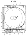
- Figure 2 is a plan sectional view of one layer and also shows a part of an auto changing mechanism of a player.
- a leaf spring 4 is fixed at its both ends to an inner surface of a side surface lb, and a convex portion 4a at the center of the leaf spring 4 biases the disk 3 against a side lc opposite the side surface lb.
- the line of action across the convex portion 4a of the leaf spring 4 is offset slightly toward the discharge side (a side of the disk insertion opening la) from a centre A of the disk 3, so that the disk 3 is held at a predetermined position inside the cartridge unless pushed out against the biasing force of the leaf spring 4.
- Push members 5 for pushing peripheral edges of the disks 3 toward the disk insertion opening la are provided at the side surface lc of the case 1.
- Each push member 5 is connected with a slide tab 7 extending outwardly from the case 1 through a slide plate 6 slidably held against the side surface lc.
- a disk 3 loaded in the case 1 is pushed at its peripheral edge by the push member 5 so as to be discharged from the case 1.
- the partially discharged disk 3 is then sent to a load position of a player by a pair of load rollers Cl of a changing mechanism of the player.
- the slide tab 7 is operated by a pawl C2 which is engaged with the slide tab 7.
- the pawl C2 is slidably provided on a drive plate C3 and is operated in a disk discharge direction to hook the slide tab 7 so as to discharge the disk 3.
- the pawl 2 is able to reciprocate in charge/discharge directions, and the drive plate C3 is movable upwardly and downwardly in a vertical direction i.e. to align with each of the disk storage positions by a drive mechanism (not shown); in use it is moved and positioned at a disk to be discharged by the above drive mechanism in accordance with a disk selection signal from the player.
- Detection tabs 8 extending outwardly from the case 1 are additionally arranged on the slide plates 6 which have the slide tabs 7 projecting therefrom.
- Each detection tab 8 is provided to detect the return position of the disk 3 at the end of disk playback, and a limit switch C4 serving as a sensor for detecting the return position is provided to the drive plate C3 of the change mechanism.
- the slide tab 7 at a storage position corresponding to the disk 3 discharged for playback is located at a discharge position indicated by the chain- dashed line in Figure 2 when the disk is discharged, and at the same time the detection tab 8 is also moved to the position indicated by the above line.
- the limit switch C4 detects the presence of the detection tab 8 at the discharge position, and the movement of the drive plate C3 is stopped thereat.
- the load rollers Cl are then rotated in the opposite direction to push the disk 3 into the storage position again.
- the push member 5, the slide tab 7, and the detection tab 8 are then returned to the storage position of the disk 3.
- the reset lever C5 is, as shown in Figure 4 which is a bottom view of the relevant part of a disk cartridge mount portion of the changing mechanism, swingable about a support shaft C6, and a drive pin C7 is attached to its drive end.
- the drive pin C7 is fitted in a heart-shaped cam groove C9 driven by the drive mechanism (not shown).
- the slide and detection tabs 7 and 8 are aligned at one end, since they are not externally locked, the psoitions of the slide tabs 7 may be varied by vibrations, acceleration, deceleration or tilting of a player for automobile or portable use.
- a click positioning mechanism (a structure wherein a sliding load is locally increased in a fixed position) is provided on the slide plate 6 formed integrally with the slide and detection tabs 7 and 8, so that the slide tab 7 is not easily moved.
- the click mechanism causes a load to act on the reset lever C5 described above and the total load depends on the maximum number of disks which can be loaded into the cartridge, so that a large load can be presented to the reset mechanism of the changing mechanism. Therefore, the following specific arrangement is provided so as not to increase the load by the click mechanism.
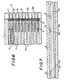
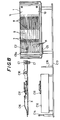
- FIG 5 is a side view of the case 1
- Figure 6 is a sectional view thereof.
- Each slide plate 6 is slidably fitted in the corresponding slide groove 9 formed at the height of the disk of the side surface lc of the case 1 and preevented from being removed by covering a side plate 10.
- the slide and detection tabs 7 and 8 extend outside the side surface lc through slits 11 in the side plate 10.
- Figures 8 and 9 are side views showing the operation of the changing mechanism of the player.
- the slide tabs 7 are aligned at one end by the reset lever C5, as shown in Figure 3.
- a disk selection operation is performed, and the drive plate C3 in Figure 2 is positioned at the height of the selected disk in the cartridge.
- the pawl C2 on the drive plate C3 in Figure 2 is moved in a removal direction to operate one of the slide tabs 7.
- the disk 3 is pushed from the front surface la of the case 1 and then discharged to the position in Figure 8 by the pair of load rollers Cl and guide roller C10.
- the drive plate C3 is moved downwardly and the disk 3 is loaded onto a turntable Cll on a player C12, as shown in Figure 9.
- the load rollers Cl and the guide roller C10 are removed from the disk 3 by stoppers C14 and C15 extending from a fixed chassis C13, and a clamp arm C16 provided on the drive plate C5 is moved downwardly so that a disk clamper 17 is set free to fix the disk 3 on the turntable Cll by its magnetic attraction.
- the projections 12a (12b) of every other slide groove 9 are offset from the projections 12a' (12b') of the corresponding adjacent slide grooves 9 along the sliding direction by the distance cx.
- the storage stages may be offset for every third storage stage, or they may be divided into an upper and a lower group of stages so that the upper group of stages is offset from the lower group of stages.
- the click positions of all the storage stages may be offset from one another.
- only the projection 12b at the storage position need be provided and the projection 12a at the removal position may be omitted as long as the pawl C2 at the side of the changing mechanism functions to prevent the slide tab 7 from being moved to the right (in the inactive direction) at the discharge position.
- click locking of the projections 12a and 12b with respect to the projection 13 is used, but click locking achieved by projections and recesses engagement may be used.
- the present invention has been described with reference to a disk cartridge for housing digital audio disks.
- the present invention is not limited to the above embodiment but can be applied to other disk-like media such as video disks, magnetic disks, and the like and independent of the recording or reproducing system used.
- the slide tabs are not shifted by an extenral force such as vibrations, so that the detection mechanism on the disk player for detecting the disk selected is not erroneously operated.
- the click locking load of all the slide tabs does not simultaneously act on an aligning mechanism, so that the required driving power of the aligning mechanism is reduced and an apparatus can be light in weight and small in size.
Landscapes
- Automatic Disk Changers (AREA)
Applications Claiming Priority (2)
| Application Number | Priority Date | Filing Date | Title |
|---|---|---|---|
| JP185286/85U | 1985-11-30 | ||
| JP1985185286U JPH0419633Y2 (fr) | 1985-11-30 | 1985-11-30 |
Publications (3)
| Publication Number | Publication Date |
|---|---|
| EP0225766A2 true EP0225766A2 (fr) | 1987-06-16 |
| EP0225766A3 EP0225766A3 (en) | 1988-10-05 |
| EP0225766B1 EP0225766B1 (fr) | 1991-07-24 |
Family
ID=16168185
Family Applications (1)
| Application Number | Title | Priority Date | Filing Date |
|---|---|---|---|
| EP86309232A Expired - Lifetime EP0225766B1 (fr) | 1985-11-30 | 1986-11-26 | Réceptacle à disques |
Country Status (8)
| Country | Link |
|---|---|
| US (1) | US4734814A (fr) |
| EP (1) | EP0225766B1 (fr) |
| JP (1) | JPH0419633Y2 (fr) |
| KR (1) | KR910006028Y1 (fr) |
| CA (1) | CA1278091C (fr) |
| DE (1) | DE3680483D1 (fr) |
| HK (1) | HK62792A (fr) |
| SG (1) | SG64292G (fr) |
Cited By (10)
| Publication number | Priority date | Publication date | Assignee | Title |
|---|---|---|---|---|
| EP0273734A2 (fr) * | 1986-12-27 | 1988-07-06 | Pioneer Electronic Corporation | Lecteur de disque double-face |
| EP0306667A1 (fr) * | 1987-08-27 | 1989-03-15 | Deutsche Thomson-Brandt GmbH | Magasin et tiroir pour la réception de supports d'enregistrement sous forme de disques |
| EP0355011A2 (fr) * | 1988-08-10 | 1990-02-21 | Matsushita Electric Industrial Co., Ltd. | Magasin à disques |
| EP0358780A1 (fr) * | 1988-03-07 | 1990-03-21 | Sony Corporation | Magasin de disques et dispositif de chargement de disques |
| GB2224877A (en) * | 1988-09-22 | 1990-05-16 | Alpine Electronics Inc | Disk playing apparatus |
| DE4135324A1 (de) * | 1991-10-25 | 1993-04-29 | Fischer Artur Werke Gmbh | Aufbewahrungseinrichtung fuer aufzeichnungstraeger |
| US5265078A (en) * | 1988-03-07 | 1993-11-23 | Sony Corporation | Disk magazine and disk loading device |
| FR2692071A1 (fr) * | 1992-04-24 | 1993-12-10 | Tanashin Denki Co | Tourne-disque. |
| FR2693022A1 (fr) * | 1992-06-26 | 1993-12-31 | Tanashin Denki Co | Tourne-disque. |
| EP0840316A1 (fr) * | 1994-05-24 | 1998-05-06 | Nsm Aktiengesellschaft | Système de restitution et/ou d'enregistrement pour disques supports de données |
Families Citing this family (28)
| Publication number | Priority date | Publication date | Assignee | Title |
|---|---|---|---|---|
| JPH073489Y2 (ja) * | 1987-09-12 | 1995-01-30 | 富士通テン株式会社 | ディスク自動交換装置のディスク引出用レバーの位置揃え機構 |
| NL8800360A (nl) * | 1988-02-15 | 1989-09-01 | Philips Nv | Cassette voor het opbergen van verscheidene schijfvormige platen, in het bijzonder optische platen. |
| NL8800859A (nl) * | 1988-04-05 | 1989-11-01 | Philips Nv | Platenwisselaar, alsmede platenspeler voorzien van de platenwisselaar. |
| US4867311A (en) * | 1988-11-21 | 1989-09-19 | Metcalf Darrell J | Computer diskette dispenser and storage device |
| US5136562A (en) * | 1989-04-11 | 1992-08-04 | Staar Development, S.A. | Automatic changer for information storage devices |
| FR2672721B1 (fr) * | 1991-02-12 | 1995-04-28 | Roger Amar | Dispositif de stockage et de lecture de supports d'informations plats. |
| EP0595225B1 (fr) * | 1992-10-26 | 1999-02-03 | Sony Corporation | Lecteur de disques |
| US5541896A (en) * | 1993-02-08 | 1996-07-30 | Ashby; S. Blake | Inter-leaved carousel for information storage mediums |
| US5450391A (en) * | 1994-01-18 | 1995-09-12 | Sony Electronics Inc. | Cartridge engagement system for optical disk cartridges |
| US5805561A (en) * | 1994-01-18 | 1998-09-08 | Sony Corporation | Cartridge engagement system for optical disk cartridges having a positionable carriage |
| JPH07220359A (ja) * | 1994-01-31 | 1995-08-18 | Sony Corp | ディスクプレーヤ装置 |
| US6034927A (en) * | 1994-10-20 | 2000-03-07 | Sony Corporation | Carriage for optical disk storage and retrieval array |
| US5576911A (en) * | 1994-10-25 | 1996-11-19 | Sony Corporation | Cartridge locking mechanism and interface |
| US6094321A (en) * | 1996-11-13 | 2000-07-25 | Sony Electronics Inc. | Recording medium assembly transport system with perpendicular engagement piece |
| US5822283A (en) * | 1997-01-29 | 1998-10-13 | Multidisc Technologies | Method for enhancing data access of CD-ROM changer |
| US5774431A (en) * | 1997-01-29 | 1998-06-30 | Multidisc Technologies | Table-of-contents caching method for stored compact discs |
| US5886974A (en) * | 1997-06-18 | 1999-03-23 | Multidisc Technologies | Compact disc loader and transport apparatus |
| US5912873A (en) * | 1997-06-18 | 1999-06-15 | Multidisc Technologies | Compact disc transporter with dual transport sites |
| FI106753B (fi) | 1997-08-07 | 2001-03-30 | Hakim Arat | Levykotelo |
| US5886960A (en) * | 1997-11-04 | 1999-03-23 | Multidisc Technologies | Optical disc system using multiple optical heads for accessing information data |
| JP3978949B2 (ja) | 1999-09-29 | 2007-09-19 | ソニー株式会社 | ディスクの記録及び/又は再生装置 |
| US6563771B1 (en) | 2000-03-22 | 2003-05-13 | Storage Technology Corporation | Digital data disc library apparatus |
| JP2005116081A (ja) * | 2003-10-08 | 2005-04-28 | Sony Corp | ディスクカートリッジ |
| JP2006059394A (ja) * | 2004-08-17 | 2006-03-02 | Fuji Photo Film Co Ltd | 記録ディスクカートリッジ |
| JP2006065941A (ja) * | 2004-08-26 | 2006-03-09 | Fuji Photo Film Co Ltd | 記録ディスクカートリッジ |
| JP4272605B2 (ja) * | 2004-09-03 | 2009-06-03 | 富士フイルム株式会社 | 記録ディスクカートリッジ |
| US7673309B2 (en) | 2005-01-20 | 2010-03-02 | Hie Electronics, Inc. | Scalable integrated high density optical data/media storage delivery system |
| CN116755519A (zh) * | 2022-02-17 | 2023-09-15 | 张傧 | 基于无线通信网络的数据加密系统 |
Citations (4)
| Publication number | Priority date | Publication date | Assignee | Title |
|---|---|---|---|---|
| JPS595466A (ja) * | 1982-07-02 | 1984-01-12 | Victor Co Of Japan Ltd | 円盤状情報記録媒体用カ−トリツジ |
| JPS5930263A (ja) * | 1982-08-10 | 1984-02-17 | Matsushita Electric Ind Co Ltd | デイスク交換装置 |
| GB2160349A (en) * | 1984-05-31 | 1985-12-18 | Sony Corp | Disc players fitted for automatic change of discs |
| EP0168107A2 (fr) * | 1984-07-11 | 1986-01-15 | Koninklijke Philips Electronics N.V. | Magasin pour plusieurs supports d'informations en forme de disques contenus dans des boîtiers et combinaison d'un lecteur de disque avec un tel magasin |
Family Cites Families (7)
| Publication number | Priority date | Publication date | Assignee | Title |
|---|---|---|---|---|
| JPS6056959B2 (ja) * | 1979-02-17 | 1985-12-12 | 株式会社テイエルブイ | バケツトフロ−ト形スチ−ムトラツプ |
| JPS6040559A (ja) * | 1983-08-12 | 1985-03-02 | Pioneer Electronic Corp | デイスク演奏装置 |
| AU578621B2 (en) * | 1983-08-31 | 1988-11-03 | Sony Corporation | Device for exchanging disks |
| JPS6056959U (ja) * | 1983-09-24 | 1985-04-20 | 松下電器産業株式会社 | デイスクジヤケツト |
| JPS6070548A (ja) * | 1983-09-27 | 1985-04-22 | Matsushita Electric Ind Co Ltd | ディスクの有無検出装置 |
| DE8416751U1 (de) * | 1984-06-01 | 1985-09-26 | IDN Inventions and Development of Novelties AG, Chur | Vorrichtung zum Aufbewahren von Aufzeichnungsträgern, insbesondere zum Einbau in Kraftfahrzeuge |
| US4655345A (en) * | 1985-11-14 | 1987-04-07 | Drake Craig D | Compact disc storage unit |
-
1985
- 1985-11-30 JP JP1985185286U patent/JPH0419633Y2/ja not_active Expired
-
1986
- 1986-11-07 CA CA000522443A patent/CA1278091C/fr not_active Expired - Lifetime
- 1986-11-24 US US06/933,886 patent/US4734814A/en not_active Expired - Lifetime
- 1986-11-26 EP EP86309232A patent/EP0225766B1/fr not_active Expired - Lifetime
- 1986-11-26 DE DE8686309232T patent/DE3680483D1/de not_active Expired - Lifetime
- 1986-11-28 KR KR2019860018708U patent/KR910006028Y1/ko not_active IP Right Cessation
-
1992
- 1992-06-23 SG SG64292A patent/SG64292G/en unknown
- 1992-08-20 HK HK627/92A patent/HK62792A/xx not_active IP Right Cessation
Patent Citations (4)
| Publication number | Priority date | Publication date | Assignee | Title |
|---|---|---|---|---|
| JPS595466A (ja) * | 1982-07-02 | 1984-01-12 | Victor Co Of Japan Ltd | 円盤状情報記録媒体用カ−トリツジ |
| JPS5930263A (ja) * | 1982-08-10 | 1984-02-17 | Matsushita Electric Ind Co Ltd | デイスク交換装置 |
| GB2160349A (en) * | 1984-05-31 | 1985-12-18 | Sony Corp | Disc players fitted for automatic change of discs |
| EP0168107A2 (fr) * | 1984-07-11 | 1986-01-15 | Koninklijke Philips Electronics N.V. | Magasin pour plusieurs supports d'informations en forme de disques contenus dans des boîtiers et combinaison d'un lecteur de disque avec un tel magasin |
Non-Patent Citations (2)
| Title |
|---|
| PATENT ABSTRACTS OF JAPAN, vol. 8, no. 125 (P-279)[1562], 12th June 1984; & JP-A-59 030 263 (MATSUSHITA DENKI SANGYO K.K.) 17-02-1984 * |
| PATENT ABSTRACTS OF JAPAN, vol. 8, no. 92 (P-271)[1529], 27th April 1984; & JP-A-59 005 466 (NIPPON VICTOR K.K.) 12-01-1984 * |
Cited By (19)
| Publication number | Priority date | Publication date | Assignee | Title |
|---|---|---|---|---|
| EP0273734A3 (en) * | 1986-12-27 | 1989-05-31 | Pioneer Electronic Corporation | Double-sided disk player |
| EP0273734A2 (fr) * | 1986-12-27 | 1988-07-06 | Pioneer Electronic Corporation | Lecteur de disque double-face |
| EP0306667A1 (fr) * | 1987-08-27 | 1989-03-15 | Deutsche Thomson-Brandt GmbH | Magasin et tiroir pour la réception de supports d'enregistrement sous forme de disques |
| EP0358780A4 (en) * | 1988-03-07 | 1991-05-22 | Sony Corporation | Disk magazine and disk loading device |
| US5265078A (en) * | 1988-03-07 | 1993-11-23 | Sony Corporation | Disk magazine and disk loading device |
| EP0358780A1 (fr) * | 1988-03-07 | 1990-03-21 | Sony Corporation | Magasin de disques et dispositif de chargement de disques |
| US5200938A (en) * | 1988-03-07 | 1993-04-06 | Sony Corporation | Disk magazine and disk loading device |
| US5058100A (en) * | 1988-05-18 | 1991-10-15 | Matsushita Electric Industrial Co., Ltd. | Disc magazine |
| EP0355011A3 (fr) * | 1988-08-10 | 1991-01-02 | Matsushita Electric Industrial Co., Ltd. | Magasin à disques |
| EP0355011A2 (fr) * | 1988-08-10 | 1990-02-21 | Matsushita Electric Industrial Co., Ltd. | Magasin à disques |
| US5093818A (en) * | 1988-08-29 | 1992-03-03 | Alpine Electronics Inc. | Disk cartridge for disk player with integrated disk changer |
| GB2224877A (en) * | 1988-09-22 | 1990-05-16 | Alpine Electronics Inc | Disk playing apparatus |
| GB2224877B (en) * | 1988-09-22 | 1993-05-19 | Alpine Electronics Inc | Disk playing apparatus |
| DE4135324A1 (de) * | 1991-10-25 | 1993-04-29 | Fischer Artur Werke Gmbh | Aufbewahrungseinrichtung fuer aufzeichnungstraeger |
| US5377175A (en) * | 1991-10-25 | 1994-12-27 | Fischerwerke Artur Fischer Gmbh & Co. Kg. | Storage device for recording media, particularly compact disks, magnetic tape cassettes and the like |
| FR2692071A1 (fr) * | 1992-04-24 | 1993-12-10 | Tanashin Denki Co | Tourne-disque. |
| US5459703A (en) * | 1992-04-24 | 1995-10-17 | Tanashin Denki Co., Ltd. | Disc player having a slider to move a disc between a disc reproducing position and a disc holder |
| FR2693022A1 (fr) * | 1992-06-26 | 1993-12-31 | Tanashin Denki Co | Tourne-disque. |
| EP0840316A1 (fr) * | 1994-05-24 | 1998-05-06 | Nsm Aktiengesellschaft | Système de restitution et/ou d'enregistrement pour disques supports de données |
Also Published As
| Publication number | Publication date |
|---|---|
| SG64292G (en) | 1992-09-04 |
| EP0225766B1 (fr) | 1991-07-24 |
| JPS6294453U (fr) | 1987-06-16 |
| CA1278091C (fr) | 1990-12-18 |
| KR910006028Y1 (ko) | 1991-08-16 |
| US4734814A (en) | 1988-03-29 |
| HK62792A (en) | 1992-08-28 |
| JPH0419633Y2 (fr) | 1992-05-06 |
| EP0225766A3 (en) | 1988-10-05 |
| KR870008917U (ko) | 1987-06-13 |
| DE3680483D1 (de) | 1991-08-29 |
Similar Documents
| Publication | Publication Date | Title |
|---|---|---|
| EP0225766B1 (fr) | Réceptacle à disques | |
| US6198716B1 (en) | Disk player including a disk chucking mechanism and plate separator device | |
| US6407982B1 (en) | Disk tray, disk storing apparatus and disk drive | |
| JPH07210972A (ja) | ディスクオートチェンジャー | |
| US5493556A (en) | Multi-disk player/recorder with biased locking means for disk cassettes | |
| EP0469643B1 (fr) | Lecteur de disques | |
| GB2266404A (en) | Disk playback device | |
| CN1226732C (zh) | 光盘装置 | |
| JP2002050165A (ja) | ディスク受板とディスク記録及び/又は再生装置 | |
| US5226025A (en) | Magazine disk player having an improved magazine detecting feature | |
| US6212156B1 (en) | Disc changer apparatus with vibration free turntable | |
| JP2000048465A (ja) | 記録媒体の収納装置 | |
| US5524003A (en) | Disk-drive apparatus waith rattle-preventing cartridge magazine | |
| JP3196957B2 (ja) | ディスク状記録担体の収納装置 | |
| EP1365396B1 (fr) | Appareil pour la reproduction de disque,dispositif changeur de disque et magasin de disque | |
| US20070263494A1 (en) | Optical Disk Device | |
| US7836462B2 (en) | Optical disk device | |
| EP1313100B1 (fr) | Dispositif empechant l'ejection d'un plateau de disque | |
| JPH0354762A (ja) | ディスク再生装置 | |
| JP3449916B2 (ja) | ディスク演奏装置 | |
| JP3449915B2 (ja) | ディスク演奏装置 | |
| EP1847993A1 (fr) | Dispositif de disque optique | |
| JPH0636437A (ja) | ディスク自動演奏装置 | |
| JP3387997B2 (ja) | Cdオートチェンジャープレヤー用トレイ引出し機構 | |
| JP2822917B2 (ja) | ディスクのローディング装置 |
Legal Events
| Date | Code | Title | Description |
|---|---|---|---|
| PUAI | Public reference made under article 153(3) epc to a published international application that has entered the european phase |
Free format text: ORIGINAL CODE: 0009012 |
|
| 17P | Request for examination filed |
Effective date: 19861201 |
|
| AK | Designated contracting states |
Kind code of ref document: A2 Designated state(s): DE FR GB |
|
| PUAL | Search report despatched |
Free format text: ORIGINAL CODE: 0009013 |
|
| AK | Designated contracting states |
Kind code of ref document: A3 Designated state(s): DE FR GB |
|
| 17Q | First examination report despatched |
Effective date: 19900926 |
|
| GRAA | (expected) grant |
Free format text: ORIGINAL CODE: 0009210 |
|
| AK | Designated contracting states |
Kind code of ref document: B1 Designated state(s): DE FR GB |
|
| ET | Fr: translation filed | ||
| REF | Corresponds to: |
Ref document number: 3680483 Country of ref document: DE Date of ref document: 19910829 |
|
| PLBE | No opposition filed within time limit |
Free format text: ORIGINAL CODE: 0009261 |
|
| STAA | Information on the status of an ep patent application or granted ep patent |
Free format text: STATUS: NO OPPOSITION FILED WITHIN TIME LIMIT |
|
| 26N | No opposition filed | ||
| PGFP | Annual fee paid to national office [announced via postgrant information from national office to epo] |
Ref country code: FR Payment date: 20011113 Year of fee payment: 16 |
|
| PGFP | Annual fee paid to national office [announced via postgrant information from national office to epo] |
Ref country code: GB Payment date: 20011128 Year of fee payment: 16 |
|
| PGFP | Annual fee paid to national office [announced via postgrant information from national office to epo] |
Ref country code: DE Payment date: 20011210 Year of fee payment: 16 |
|
| REG | Reference to a national code |
Ref country code: GB Ref legal event code: IF02 |
|
| PG25 | Lapsed in a contracting state [announced via postgrant information from national office to epo] |
Ref country code: GB Free format text: LAPSE BECAUSE OF NON-PAYMENT OF DUE FEES Effective date: 20021126 |
|
| PG25 | Lapsed in a contracting state [announced via postgrant information from national office to epo] |
Ref country code: DE Free format text: LAPSE BECAUSE OF NON-PAYMENT OF DUE FEES Effective date: 20030603 |
|
| GBPC | Gb: european patent ceased through non-payment of renewal fee | ||
| PG25 | Lapsed in a contracting state [announced via postgrant information from national office to epo] |
Ref country code: FR Free format text: LAPSE BECAUSE OF NON-PAYMENT OF DUE FEES Effective date: 20030731 |
|
| REG | Reference to a national code |
Ref country code: FR Ref legal event code: ST |