EP0225443A1 - Punktschweissgerät für die Dentaltechnik - Google Patents
Punktschweissgerät für die Dentaltechnik Download PDFInfo
- Publication number
- EP0225443A1 EP0225443A1 EP86112858A EP86112858A EP0225443A1 EP 0225443 A1 EP0225443 A1 EP 0225443A1 EP 86112858 A EP86112858 A EP 86112858A EP 86112858 A EP86112858 A EP 86112858A EP 0225443 A1 EP0225443 A1 EP 0225443A1
- Authority
- EP
- European Patent Office
- Prior art keywords
- welding
- capacitor
- welding device
- spot welding
- parts
- Prior art date
- Legal status (The legal status is an assumption and is not a legal conclusion. Google has not performed a legal analysis and makes no representation as to the accuracy of the status listed.)
- Granted
Links
- 238000003466 welding Methods 0.000 title claims abstract description 63
- 239000003990 capacitor Substances 0.000 claims abstract description 38
- 238000005516 engineering process Methods 0.000 claims description 3
- 210000002105 tongue Anatomy 0.000 description 9
- 238000000034 method Methods 0.000 description 6
- 239000000463 material Substances 0.000 description 4
- 238000003825 pressing Methods 0.000 description 4
- 238000003860 storage Methods 0.000 description 4
- 238000005476 soldering Methods 0.000 description 3
- 238000010586 diagram Methods 0.000 description 2
- 239000010935 stainless steel Substances 0.000 description 2
- 230000015556 catabolic process Effects 0.000 description 1
- 239000004020 conductor Substances 0.000 description 1
- 238000007599 discharging Methods 0.000 description 1
- 238000010891 electric arc Methods 0.000 description 1
- 239000000155 melt Substances 0.000 description 1
- 239000002184 metal Substances 0.000 description 1
- 229910052751 metal Inorganic materials 0.000 description 1
- 239000010970 precious metal Substances 0.000 description 1
- 229910000923 precious metal alloy Inorganic materials 0.000 description 1
- 239000000523 sample Substances 0.000 description 1
- 238000007711 solidification Methods 0.000 description 1
- 230000008023 solidification Effects 0.000 description 1
- 229910001220 stainless steel Inorganic materials 0.000 description 1
- 229910001256 stainless steel alloy Inorganic materials 0.000 description 1
- 230000001960 triggered effect Effects 0.000 description 1
Images
Classifications
-
- B—PERFORMING OPERATIONS; TRANSPORTING
- B23—MACHINE TOOLS; METAL-WORKING NOT OTHERWISE PROVIDED FOR
- B23K—SOLDERING OR UNSOLDERING; WELDING; CLADDING OR PLATING BY SOLDERING OR WELDING; CUTTING BY APPLYING HEAT LOCALLY, e.g. FLAME CUTTING; WORKING BY LASER BEAM
- B23K9/00—Arc welding or cutting
- B23K9/22—Percussion welding
-
- A—HUMAN NECESSITIES
- A61—MEDICAL OR VETERINARY SCIENCE; HYGIENE
- A61C—DENTISTRY; APPARATUS OR METHODS FOR ORAL OR DENTAL HYGIENE
- A61C13/00—Dental prostheses; Making same
- A61C13/20—Methods or devices for soldering, casting, moulding or melting
-
- B—PERFORMING OPERATIONS; TRANSPORTING
- B23—MACHINE TOOLS; METAL-WORKING NOT OTHERWISE PROVIDED FOR
- B23K—SOLDERING OR UNSOLDERING; WELDING; CLADDING OR PLATING BY SOLDERING OR WELDING; CUTTING BY APPLYING HEAT LOCALLY, e.g. FLAME CUTTING; WORKING BY LASER BEAM
- B23K9/00—Arc welding or cutting
- B23K9/20—Stud welding
Definitions
- the invention relates to a spot welding device for dental technology, a capacitor arrangement being connected to a low-voltage rectifier circuit and supplying a current for an arc.
- DE-OS 32 227 692 describes a spot welding device of the type mentioned. There the parts to be welded are held on a model and fixed by pressing parts and connected to a pole of the welding current source. The other pole of the welding current source rests on an electrode which is brought up to the welding point. The arc burns between this electrode and the junction. Difficulties arise for lifting off the welding electrode so that it is not integrated into the welded connection. In addition, welding of parts in a free direction is not possible.
- DE-OS 33 27 882 describes a welding device for resistance pressure welding.
- the welding current flows between the jaws of a welding gun.
- the jaws are pressed onto the parts to be welded.
- the scope of this device is very limited. Due to the comparatively high welding current, the welding of sensitive and fine denture parts is not possible because they would melt away.
- GB-PS 12 81 414 describes an arc welding device in which an arc burns between two electrodes of a probe. This device can only be used if the parts to be welded can be placed between the electrodes, which is only possible under restricted spatial conditions.
- the object of the invention is the mutual fixation of components, in particular dental prosthesis parts made of stainless steel and precious metal alloys in free alignment or on the model.
- the capacitor arrangement is connected to the parts to be welded by means of welding guns and in that the arc burns between the parts to be welded.
- the invention differs from the prior art in that the welded connection does not take place between two electrodes or a welding pad and an electrode under pressure, but rather by an arc forming between the parts to be welded in the proximity or punctiform contact area.
- the point-like contact areas evaporate so that an arc is formed.
- the material is melted and the parts are fixed against one another by solidification in point-shaped and thread-like bridges, so that subsequent soldering work is possible.
- the parts can be brought together freely. You can weld a wire tip directly to a plate.
- the welding takes place immediately when the parts approach or touch each other.
- the low-voltage rectifier circuit provides a DC voltage of up to around 65 volts that is permitted by the safety regulations.
- a switching element is inserted in the discharge circuit of the capacitor arrangement.
- the switching element can be foot-operated.
- the switching element itself comprises an electronic switch, in particular a thyristor, which is suitable for switching high welding currents. Such a switching element makes it possible to first fix the parts to be welded precisely and then to trigger the welding pulse.
- the intensity of the welding pulse can be adapted to the respective use in that several capacitors of different capacitance are provided in parallel to one another and each over a selector circuit can bring a capacitor into charge standby. Such a gradual adjustment is easily reproducible and is sufficient in practice. It is preferable to a continuous setting.
- the voltage-carrying capacitor pole is connected to a plurality of connection points with the interposition of inductors or resistors. Pulse durations of 1 to 10 ms are easily achieved. The smaller the cross section of the parts to be welded, in particular the thinner the wire in question, the smaller the welding pulse must be so that the material does not burn away in the electric arc.
- the connection points can be electrical or electronic switching stages, they can also be realized by connection sockets. In practice, two or three periods of the welding pulse are sufficient to adapt to the welding requirements that occur.
- the readiness for welding after the end of the charging process is indicated by the fact that the voltage-carrying capacitor pole is connected to a Zener diode, to which a light-emitting diode is connected in series.
- a capacitor discharge is possible in that the voltage-carrying capacitor pole is connected to a discharge button via a discharge resistor.
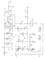
- the circuit diagram shows a power supply unit 1, a rectifier part 2 and a storage part 3 for storing the charge for the welding pulse.
- Connecting lines 4 and 5 are connected to the storage part 3, on each of which a welding gun 6, 7 is seated.
- Each welding gun 6, 7 enables the holder and the electrical connection of a dental part 8 or 9 made of electrically conductive material.
- wires 8 or 9 can just as well be dental prostheses, holding plates or the like.
- the dental parts 8 and 9 can be welded together by the spot welding device according to the invention, which will be explained further below.
- the power pack 1 comprises a fuse 10, a switch 11 and control lamps 12, 13, 14.
- the control lamp 12 shows the switch 11 in the switched-on state.
- the indicator lamp 13 is on via a relay contact tongue 15 and the indicator lamp 14 on a contact tongue 16 switchable, which is explained in detail.
- the power supply unit 1 also includes the primary coil 17 of a transformer 18 which has two secondary coils 19 and 20 connected in series, which belong to the rectifier part 2.
- Various switches are located in the connecting line of the secondary coils 19 and 20, namely a non-latching button 21, a latching permanent function button 22 and a relay contact tongue 23.
- the secondary coils 19 and 20 each emit an alternating voltage of 12 V. This AC voltage is rectified in a rectifier switch 24, so that a pulsed DC voltage of 24 V is obtained.
- the positive pole of the rectifier circuit 24 is connected to ground 27.
- the storage part 3 comprises, as charge storage, a plurality of capacitors 25 and 26 which have different capacities and are therefore used for welding pulses of different sizes and intensities.
- the two capacitors 26 are connected in parallel, so that twice the capacitance is available.
- the positive capacitor pole is connected to one pole of a two-pole connection socket 28 or 29.
- the other pole of this connector is connected to ground 27. So normally the connection between the positive capacitor pole and ground 27 is open.
- the negative capacitor poles are brought together and are connected to connection points or connection sockets 32, 33, 34 with the interposition of inductors 30, 31. Inductors 30 and 31 serve to change the duration of a welding pulse.
- the connecting lines 4 and 5 are each connected to two-pole plugs 36 and 37, respectively.
- the plug 36 contains an internal bridge 38 which bridges the two poles of the plug. So if the plug 36 is inserted into a socket 28 or 29, the poles of the socket 28 or 29 are thereby connected to one another, so that the capacitor 25 or 26 connected to the respective socket is connected to ground 27.
- the plug 36 enables the selection of a capacitor 25 or 26 and thus the power of the respective welding pulse.
- the plug 36 closes the charging circuit for the capacitor in question, so that only the capacitor in question is charged.
- the plug 37 is plugged into one of the connection sockets 32, 33, 34 and defines the welding time, since the corresponding welding current must flow through the respective inductor 30 or 31 or choke coil.
- the plugs can also be replaced by electronic switching stages, which enable the respective discharge to be selected.
- a switching element 44 which comprises an electronic switch, e.g. a thyristor that is suitable for switching the high welding current.
- the switching element 44 can be foot-operated. This makes it possible to trigger the welding pulse when the parts to be welded are precisely aligned.
- the charging current of the rectifier circuit 24 flows through a series resistor 35 and also through a relay 39 which actuates the two relay contact tongues 15 and 23.
- the negative capacitor poles are connected to a zener diode 40 to which a light-emitting diode 41 is connected.
- the secondary coils 19 and 20 each provide a voltage of 12 V, the rectifier circuit 24 provides a pulsed 24 V DC voltage.
- the respective capacitor charges to a voltage of approx. 36 V, taking into account the effective values. This voltage causes the breakdown of the Zener diode 40, so that the LED 41 indicates the completion of the charging process.
- the function of the spot welder is as follows.
- the switch 11 switches on the mains voltage.
- the operational readiness of the device is indicated by the control lamp 12.
- the respective power of the welding pulse and the duration of the welding pulse must be selected by inserting the plug 6.
- the welding guns 6 and 7 are each connected to conductive dental parts 8 and 9, which are to be welded together. With thin wires, the power of the welding pulse must be as small as possible so that the wire in the arc does not burn away.
- a one-time welding pulse can be generated.
- the non-latching button 21 is actuated so that a charging current flows.
- This charging current excites the relay 39, which attracts the relay contact blades 15 and 23.
- the relay contact tongue 15 closes the circuit for the indicator lamp 13, which indicates the charging process.
- the relay contact tongue 23 is a self-holding contact tongue for the non-latching button 21.
- the capacitor 25 or 26 which is respectively switched on is charged.
- the zener diode 40 ignites, so that the light-emitting diode 41 indicates the end of the charging process. Now the welding can be carried out by moving the welding guns 6 and 7 together with the dental parts 8 and 9.
- the dental parts 8 and 9 are brought into contact with one another at the respectively desired welding point, so that the discharge current of the capacitor ignites an arc and the material in the welding point melts. This creates a cohesive weld connection.
- the discharge current can also be switched by the trigger button 44 after the parts to be welded have previously been fixed.
- the capacitor 25 has e.g. a capacitance of 7000 ⁇ F, the capacitor 26 of 10000 ⁇ F.
- the inductors or choke coils 30 and 31 each have approximately 30 ⁇ H. This enables maxiamle welding currents of up to 340 A and pulse durations between 1 and 10 ms to be achieved.
- the welding pulse can thus be adapted to the particular application, in particular the material to be welded.
- a continuous sequence of welding pulses can be provided by actuating the latching continuous function button 22. Together with the permanent function button 22, the contact tongue 16 is also switched so that the control lamp 14 indicates the continuous welding function. After pressing the continuous function button 22, the charging current flows in the manner described. The completion of the charging process is also indicated by the LED 41. You can now weld. A charging current flows again after each weld. Weldings can therefore continue to be carried out as soon as the charge state is reached and is indicated by the light-emitting diode 41.
- the capacitor can be discharged by pressing the discharge button 43 via the discharge resistor 42.
Landscapes
- Engineering & Computer Science (AREA)
- Health & Medical Sciences (AREA)
- Physics & Mathematics (AREA)
- Plasma & Fusion (AREA)
- Mechanical Engineering (AREA)
- Life Sciences & Earth Sciences (AREA)
- Dentistry (AREA)
- Epidemiology (AREA)
- Oral & Maxillofacial Surgery (AREA)
- Animal Behavior & Ethology (AREA)
- General Health & Medical Sciences (AREA)
- Public Health (AREA)
- Veterinary Medicine (AREA)
- Arc Welding Control (AREA)
- Resistance Welding (AREA)
- Laser Beam Processing (AREA)
Abstract
Description
- Die Erfindung betrifft ein Punktschweißgerät für die Dentaltechnik, wobei an eine Niederspannungs-Gleichrichterschaltung eine Kondensatoranordnung angeschlossen ist, die einen Strom für einen Lichtbogen liefert.
- In der Dentaltechnik müssen für Zahnprothesen, Gebißaufbauten und dergleichen zahlreiche Metallteile aus Edelmetallen, Edelstahl und dergleichen fest miteinander verbunden, insbesondere in ein Lötbett eingebettet werden. Dieses gilt auch für Stützdrähte und andere Haltevorrichtungen aus Draht. Es ist jedoch sehr schwierig, die einzelnen Teile so festzulegen oder zu fixieren, daß sie sich beim Löten oder der weiteren Bearbeitung nicht verschieben können.
- Die DE-OS 32 227 692 beschreibt ein Punktschweißgerät der genannten Art. Dort sind die zu schweißenden Teile auf einem Modell gehalten und durch Andrückteile festgelegt sowie mit einem Pol der Schweißstromquelle verbunden. Der andere Pol der Schweißstromquelle liegt an einer Elektrode an, die an die Schweißstelle herangeführt wird. Der Lichtbogen brennt zwischen dieser Elektrode und der Verbindungsstelle. Hier ergeben sich Schwierigkeiten für das Abheben der Schweißelektrode, damit dieselbe nicht in die Schweißverbindung eingebunden wird. Außerdem ist ein Schweißen von Teilen in freier Asurichtung nicht möglich.
- Die DE-OS 33 27 882 beschreibt ein Schweißgerät für eine Widerstandsdruckschweißung. Der Schweißstrom fließt zwischen den Backen einer Schweißzange. Die Backen werden auf die zu schweißenden Teile gepreßt. Der Anwendungsbereich dieses Gerätes ist sehr eingeschränkt. Infolge des vergleichsweise hohen Schweißstromes ist das Schweißen von empfindlichen und feinen Zahnprothesenteilen nicht möglich, da dieselbe wegschmelzen würden.
- Die GB-PS 12 81 414 beschreibt ein Lichtbogenschweißgerät, bei dem ein Lichtbogen wzischen zwei Elektroden einer Sonde brennt. Dieses Gerät ist nur dann anwendbar, wenn die zu schweißenden Teile zwischen die Elektroden gebracht werden können, was nur unter eingeschränkten räumlichen Bedingungen möglich ist.
- Aufgabe der Erfindung ist die gegenseitige Fixierung von Bauteilen, insbesondere von Zahnprothesenteilen aus Edelstahl und Edelmetallegierungen in freier Ausrichtung oder auf dem Modell.
- Diese Aufgabe wird nach der Erfindung dadurch gelöst, daß die Kondensatoranordnung über Schweißzangen mit den zu schweißenden Teilen verbunden ist und daß der Lichtbogen zwischen den zu schweißenden Teilen brennt.
- Die Erfindung unterscheidet sich insofern vom Stand der Technik, als die Schweißverbindung nicht zwischen zwei Elektroden bzw. einer Schweißunterlage und einer Elektrode unter Druck erfolgt, sondern durch einen sich zwischen den zu schweißenden Teilen im Annäherungsoder punktförmigen Berührungsbereich ausbildenden Lichtbogen. Die punktförmigen Berührungsbereiche verdampfen, so daß sich ein Lichtbogen ausbildet. Es erfolgt eine Werkstoffaufschmelzung und durch Erstarrung in spitzenförmigen und fadenförmigen Brücken eine Fixierung der Teile gegeneinander, so daß anschließende Lötarbeiten möglich sind. Die Teile können frei zusammengeführt werden. Man kann eine Drahtspitze unmittelbar an ein Platte anschweißen. Die Schweißung erfolgt unmittelbar bei der gegenseitigen Annäherung bzw. Berührung der Teile. Die Niederspannungs-Gleichrichterschaltung stellt eine nach den Sicherheitsvorschriften zulässige Gleichspannung bis zu etwa 65 Volt bereit.
- Zur Auslösung der Entladung und damit des Lichtbogens ist vorgesehen, daß in den Entladestromkreis der Kondensatoranordnung ein Schaltelement eingefügt ist. Das Schaltelement kann fußbetätigt sein. Das Schaltelement selbst umfaßt einen elektronischen Schalter, insbesondere einen Thyristor, der zur Schaltung hoher Schweißströme geeignet ist. Ein solches Schaltelement ermöglicht es, die zu verschweißenden Teile zunächst genau zu fixieren und dann den Schweißimpuls auszulösen.
- Die Intensität des Schweißimpulses läßt sich dadurch an die jeweilige Verwendung anpassen, daß mehrere Kondensatoren unterschiedlicher Kapazität parallel zueinander vorgesehen sind und jeweils über eine Wählschaltung ein Kondensator in Ladebereitschaft gebracht werden kann. Eine solche stufenweise Einstellung ist leicht reproduzierbar und reicht in der Praxis aus. Sie ist einer stufenlosen Einstellung vorzuziehen.
- Zur Beeinflussung der Dauer des Schweißimpulses ist vorgesehen, daß der spannungführende Kondensatorpol unter Zwischenschaltung von Induktivitäten oder Widerständen mit mehreren Anschlußstellen verbunden ist. Man erreicht leicht Impulsdauern von 1 bis 10 ms. Je kleiner der Querschnitt der zu verschweißenden Teile, insbesondere je dünnner der jeweilige Draht ist, um so kleiner muß der Schweißimpuls sein, damit der Werkstoff in dem elektrischen Lichtbogen nicht wegbrennt. Die Anschlußstellen können elektrische oder elektronische Schaltstufen sein, sie können auch durch Anschlußbuchsen verwirklicht sein. Zwei oder drei Zeitdauern des Schweißimpulses sind in der Praxis in Anpassung an die auftretenden Schweißanforderungen ausreichend.
- Die Schweißbereitschaft nach Beendigung des Aufladevorgangs wird dadurch angezeigt, daß der spannungführende Kondensatorpol mit einer Zenerdiode verbunden ist, zu der in Reihe eine Leuchtdiode geschaltet ist.
- Eine Kondensatorentladung ist dadurch möglich, daß der spannungführende Kondensatorpol über einen Entladewiderstand mit einem Entladetaster verbunden ist.
- Eine Ausführungsform der Erfindung wird im folgenden unter Bezugnahme auf das anliegende Schaltbild erläutert.
- Das Schaltbild zeigt einen Netzteil 1, einen Gleichrichterteil 2 und einen Speicherteil 3 zur Speicherung der Ladung für den Schweißimpuls. An den Speicherteil 3 sind Verbindungsleitungen 4 und 5 angeschlossen, an denen jeweils eine Schweißzange 6, 7 sitzt. Jede Schweißzange 6, 7 ermöglicht die Halterung und den elektrischen Anschluß eines Dentalteiles 8 oder 9 aus elektrisch leitendem Werkstoff. In dem dargestellten Beispiel handelt es sich um Drähte 8 oder 9. Es kann sich genau so gut um Zahnprothesen, halteplatten oder dergleichen handeln. Die Dentalteile 8 und 9 können durch das Punktschweißgerät nach der Erfindung miteinander verschweißt werden, was weiter unten erläutert wird.
- Daz Netzteil 1 umfaßt eine Sicherung 10, einen Schalter 11 und Kontrollampen 12, 13, 14. Die Kontrollampe 12 zeigt den Einschaltzustand des Schalters 11 an. Die Kontrollampe 13 ist über eine Relaiskontaktzunge 15 und die Kontrollampe 14 über eine Kontaktzunge 16 ein schaltbar, was noch im einzelnen erläutert wird. Das Netzteil 1 umfaßt auch die Primärspule 17 eines Transformators 18, der zwei hintereinander geschaltete Sekundärspulen 19 und 20 hat, die zu dem Gleichrichterteil 2 gehören.
- In der Verbindungsleitung der Sekundärspulen 19 und 20 befinden sich verschiedene Schalter, nämlich ein nichtrastender Taster 21, ein rastender Dauerfunktionstaster 22 und eine Relaiskontaktzunge 23. Die Sekundärspulen 19 und 20 geben jeweils eine Wechselspannung von 12 V ab. Diese Wechselspannung wird in einer Gleichrichterschalter 24 gleichgerichtet, so daß man eine gepulste Gleichspannung von 24 V erhält. Der positive Pol der Gleichrichterschaltung 24 ist mit Masse 27 verbunden.
- Der Speicherteil 3 umfaßt als Ladungsspeicher mehrere Kondensatoren 25 und 26, die unterschiedliche Kapazität haben und somit für Schweißimpulse unterschiedlicher Größe und Intensität Verwendung finden. Die beiden Kondensatoren 26 sind parallel geschaltet, so daß die doppelte Kapazität zur Verfügung steht. Jeweils der positive Kondensatorpol ist mit einem Pol einer zweipoligen Anschlußbuchse 28 bzw. 29 verbunden. Der jeweils andere Pol dieser Anschlußbuchse ist mit Masse 27 verbunden. Normalerweise ist also die Verbindung zwischen dem positiven Kondensatorpol und Masse 27 offen. Die negativen Kondensatorpole sind zusammengeführt und liegen unter Zwischenschaltung von Induktivitäten 30, 31 an Anschlußstellen oder Anschlußbuchsen 32, 33, 34 an. Die Induktivitäten 30 und 31 dienen zur Änderung der Dauer eines Schweißimpulses.
- Die Verbindungsleitungen 4 und 5 sind jeweils mit zweipoligen Steckern 36 bzw. 37 verbunden. Der Stecker 36 enthält eine interne Brücke 38, die die beiden Pole des Steckers überbrückt. Wenn also der Stecker 36 in eine Anschlußbuchse 28 oder 29 eingesteckt wird, so werden dadurch die Pole der Anschlußbuchse 28 oder 29 miteinander verbunden, so daß der an die jeweilige Anschlußbuchse angeschlossene Kondensator 25 bzw. 26 mit Masse 27 verbunden ist. Der Stecker 36 ermöglicht die Auswahl eines Kondensators 25 oder 26 und damit der Leistung des jeweiligen Schweißimpulses. Der Stecker 36 schließt den Ladestromkreis für den betreffenden Kondensator, so daß nur der betreffende Kondensator aufgeladen wird. Der Stecker 37 wird in eine der Anschlußbuchsen 32, 33, 34 eingesteckt und legt die schweißdauer fest, da der entsprechende Schweißstrom über die jeweils zwischengeschaltete Induktivität 30 oder 31 bzw. Drosselspule fließen muß.
- Die Stecker kann man auch durch elektronische Schaltstufen ersetzen, die eine Auswahl der jeweiligen Entladung ermöglichen. In diesem Fall ist ein Schaltelement 44 vorhanden, das einen elektronischen Schalter umfaßt, z.B. einen Thyristor, der zur Schaltung des hohen Schweißstromes geeignet ist. Das Schaltelement 44 kann fußbetätigt sein. Dadurch ist es möglich, den Schweißimpuls dann auszulösen, wenn die zu schweißenden Teile genau ausgerichtet sind.
- Der Ladestrom der Gleichrichterschaltung 24 fließt über einen Vorwiderstand 35 und auch durch ein Relais 39, das die beiden Relaiskontaktzungen 15 und 23 betätigt.
- Ferner sind die negativen Kondensatorpole mit einer Zenerdiode 40 verbunden, an die eine Leuchtdiode 41 angeschlossen ist.
- Schließlich ist ein Entladewiderstand 42 und ein Entladetaster 43 vorgesehen.
- Die Sekundärspulen 19 und 20 stellen jeweils eine Spannung von 12 V bereit, die Gleichrichterschaltung 24 stellt eine gepulste 24 V-Gleichspannung bereit. Infolgedessen lädt sich der jeweilige Kondensator unter Berücksichtigung der Effektivwerte auf eine Spannung von ca. 36 V auf. Diese Spannung bewirkt den Durchbruch der Zenerdiode 40, so daß die Leuchtdiode 41 die Beendigung des Ladevorgangs anzeigt.
- Die Funktion des Punktschweißgeräts ist folgende. Der Schalter 11 schaltet die Netzspannung ein. Die Betriebsbereitschaft des Geräts wird durch die Kontrollampe 12 angezeigt. Als nächstes muß durch Einstecken des Steckers 6 die jeweilige Leistung des Schweißimpulses und durch den Stecker 37 die Dauer des Schweißimpulses ausgewählt werden. Die Schweißzangen 6 und 7 sind jeweils mit leitenden Dentalteilen 8 und 9 verbunden, die miteinander verschweißt werden sollen. Bei dünnen Drähten muß die Leistung des Schweißimpulses möglichst klein sein, damit der Draht im Lichtbogen nicht wegbrennt.
- Es kann ein einmaliger Schweißimpuls erzeugt werden. Hierzu wird der nichtrastende Taster 21 betätigt, so daß ein Ladestrom fließt. Dieser Ladestrom erregt das Relais 39, das die Relaiskontaktzungen 15 und 23 anzieht. Die Relaiskontaktzunge 15 schließt den Stromkreis für die Kontrollampe 13, die den Ladevorgang anzeigt. Die Relaiskontaktzunge 23 ist eine Selbsthaltekontaktzunge für den nichtrastenden Taster 21. Der jeweils angeschaltete Kondensator 25 oder 26 wird aufgeladen. Bei Erreichen der Ladespannung zündet die Zenerdiode 40, so daß die Leuchtdiode 41 die Beendigung des Ladevorgangs anzeigt. Jetzt kann die Schweißung erfolgen, indem die Schweißzangen 6 und 7 mit den Dentalteilen 8 und 9 aufeinander zubewegt werden. Die Dentalteile 8 und 9 werden an der jeweils gewünschten Schweißstelle miteinander zur Berührung gebracht, so daß der Entladestrom des Kondensators einen Lichtbogen zündet und das Material in der Schweißstelle aufschmilzt. Hierdurch erfolgt eine stoffschlüssige Schweißverbindung. Der Entladestrom kann auch durch die Auslösetaste 44 geschaltet werden, nachdem zuvor die zu verschweißenden Teile fixiert sind.
- Der Kondensator 25 hat z.B. eine Kapazität von 7000 µF, der Kondensator 26 von 10000 µF. Die Induktivitäten oder Drosselspulen 30 und 31 haben jeweils etwa 30 µH. Damit lassen sich maxiamle Schweißströme bis zu 340 A und Impulsdauern zwischen 1 und 10 ms realisieren. Der Schweißimpuls kann so dem jeweiligen Anwendungsfall, insbesondere dem zu verschweißenden Material angepaßt werden.
- Durch die Entladung des Kondensators sinkt die Spannung am Relais 39 unter die Anzugspannung ab, so daß damit auch die Relaiskontaktzungen 15 und 23 abfallen. Nachdem der Kondensator entladen ist, kann ein neuer Schweißvorgang durch Betätigung des Tasters 21 ausgelöst werden.
- Eine Dauerfolge von Schweißimpulsen kann durch Betätigung des rastenden Dauerfunktionstasters 22 bereitgestellt werden. Gemeinsam mit dem Dauerfunktionstaster 22 wird auch die Kontaktzunge 16 geschaltet, so daß die Kontrollampe 14 die Dauerschweißfunktion anzeigt. Nach Eindrücken des Dauerfunktionstasters 22 fließt der Ladestrom in der beschriebenen Weise. Die Beendigung des Ladevorgangs wird ebenfalls durch die Leuchtdiode 41 angezeigt. Es kann jetzt eine Schweißung erfolgen. Jeweils im Anschluß an diese Schweißung fließt wieder ein Ladestrom. Es können daher fortgesetzt Schweißungen durchgeführt werden, sobald der Ladezustand erreicht und durch die Leuchtdiode 41 angezeigt ist.
- Wenn der Kondensator geladen ist und trotzdem keine Schweißung durchgeführt werden soll, so kann der Kondensator durch Betätigung der Entladetaste 43 über den Entladewiderstand 42 entladen werden.
Claims (6)
Priority Applications (1)
| Application Number | Priority Date | Filing Date | Title |
|---|---|---|---|
| AT86112858T ATE46257T1 (de) | 1985-12-03 | 1986-09-17 | Punktschweissgeraet fuer die dentaltechnik. |
Applications Claiming Priority (2)
| Application Number | Priority Date | Filing Date | Title |
|---|---|---|---|
| DE19853542674 DE3542674A1 (de) | 1985-12-03 | 1985-12-03 | Punktschweissgeraet fuer die dentaltechnik |
| DE3542674 | 1985-12-03 |
Publications (3)
| Publication Number | Publication Date |
|---|---|
| EP0225443A1 true EP0225443A1 (de) | 1987-06-16 |
| EP0225443B1 EP0225443B1 (de) | 1989-09-13 |
| EP0225443B2 EP0225443B2 (de) | 1995-09-13 |
Family
ID=6287464
Family Applications (1)
| Application Number | Title | Priority Date | Filing Date |
|---|---|---|---|
| EP86112858A Expired - Lifetime EP0225443B2 (de) | 1985-12-03 | 1986-09-17 | Punktschweissgerät für die Dentaltechnik |
Country Status (4)
| Country | Link |
|---|---|
| EP (1) | EP0225443B2 (de) |
| JP (1) | JPS62134182A (de) |
| AT (1) | ATE46257T1 (de) |
| DE (2) | DE3542674A1 (de) |
Cited By (2)
| Publication number | Priority date | Publication date | Assignee | Title |
|---|---|---|---|---|
| DE3726156A1 (de) * | 1987-08-06 | 1989-02-16 | Scheu Dental Inh Rudolf Scheu | Verfahren zur herstellung von dentalprothesen unter einsatz eines punktschweissgeraetes |
| EP3138649A1 (de) * | 2015-09-01 | 2017-03-08 | Harms & Wende GmbH & Co. KG | Vorrichtung und verfahren zum kondensatorentladeschweissen |
Families Citing this family (2)
| Publication number | Priority date | Publication date | Assignee | Title |
|---|---|---|---|---|
| DE4201247C2 (de) * | 1992-01-18 | 1996-02-15 | Christian Dahlmann | Lichtbogenpunktschweißgerät für die Dentaltechnik |
| DE102009028945C5 (de) * | 2009-08-27 | 2013-08-08 | Hilti Aktiengesellschaft | Handschweißgerät |
Citations (8)
| Publication number | Priority date | Publication date | Assignee | Title |
|---|---|---|---|---|
| US2836703A (en) * | 1956-06-19 | 1958-05-27 | Bell Telephone Labor Inc | Low voltage arc welding circuit for use with percussion hand welder |
| FR1555494A (de) * | 1965-03-18 | 1969-01-31 | ||
| GB1281414A (en) * | 1968-12-31 | 1972-07-12 | Commissariat Energie Atomique | Surgical electric welding apparatus |
| DE2108105B2 (de) * | 1971-02-19 | 1977-02-03 | Hilti Ag, Schaan (Liechtenstein) | Kondensator-entladungs-bolzenschweissgeraet |
| DE2658332A1 (de) * | 1976-12-23 | 1978-06-29 | Degussa | Verfahren zum stumpfschweissen von draehten und litzen |
| DE2827020A1 (de) * | 1978-06-20 | 1980-01-10 | Buechi Lab Tech | Verfahren und vorrichtung zum elektrischen schweissen von festsitzenden metallischen zahnersatzteilen |
| DE3227692A1 (de) * | 1982-07-24 | 1984-02-02 | Degussa Ag, 6000 Frankfurt | Schweissvorrichtung zum verbinden von positionierten teilen |
| DE3327882A1 (de) * | 1983-05-02 | 1984-11-08 | BIOTECO Biomedical Equipments Technical Supplies Computer Applications S.p.A., Mailand/Milano | Schweissvorrichtung fuer metallprothesen |
-
1985
- 1985-12-03 DE DE19853542674 patent/DE3542674A1/de not_active Withdrawn
-
1986
- 1986-09-17 EP EP86112858A patent/EP0225443B2/de not_active Expired - Lifetime
- 1986-09-17 AT AT86112858T patent/ATE46257T1/de not_active IP Right Cessation
- 1986-09-17 DE DE8686112858T patent/DE3665534D1/de not_active Expired
- 1986-10-29 JP JP61258104A patent/JPS62134182A/ja active Pending
Patent Citations (8)
| Publication number | Priority date | Publication date | Assignee | Title |
|---|---|---|---|---|
| US2836703A (en) * | 1956-06-19 | 1958-05-27 | Bell Telephone Labor Inc | Low voltage arc welding circuit for use with percussion hand welder |
| FR1555494A (de) * | 1965-03-18 | 1969-01-31 | ||
| GB1281414A (en) * | 1968-12-31 | 1972-07-12 | Commissariat Energie Atomique | Surgical electric welding apparatus |
| DE2108105B2 (de) * | 1971-02-19 | 1977-02-03 | Hilti Ag, Schaan (Liechtenstein) | Kondensator-entladungs-bolzenschweissgeraet |
| DE2658332A1 (de) * | 1976-12-23 | 1978-06-29 | Degussa | Verfahren zum stumpfschweissen von draehten und litzen |
| DE2827020A1 (de) * | 1978-06-20 | 1980-01-10 | Buechi Lab Tech | Verfahren und vorrichtung zum elektrischen schweissen von festsitzenden metallischen zahnersatzteilen |
| DE3227692A1 (de) * | 1982-07-24 | 1984-02-02 | Degussa Ag, 6000 Frankfurt | Schweissvorrichtung zum verbinden von positionierten teilen |
| DE3327882A1 (de) * | 1983-05-02 | 1984-11-08 | BIOTECO Biomedical Equipments Technical Supplies Computer Applications S.p.A., Mailand/Milano | Schweissvorrichtung fuer metallprothesen |
Cited By (2)
| Publication number | Priority date | Publication date | Assignee | Title |
|---|---|---|---|---|
| DE3726156A1 (de) * | 1987-08-06 | 1989-02-16 | Scheu Dental Inh Rudolf Scheu | Verfahren zur herstellung von dentalprothesen unter einsatz eines punktschweissgeraetes |
| EP3138649A1 (de) * | 2015-09-01 | 2017-03-08 | Harms & Wende GmbH & Co. KG | Vorrichtung und verfahren zum kondensatorentladeschweissen |
Also Published As
| Publication number | Publication date |
|---|---|
| JPS62134182A (ja) | 1987-06-17 |
| EP0225443B2 (de) | 1995-09-13 |
| EP0225443B1 (de) | 1989-09-13 |
| DE3665534D1 (en) | 1989-10-19 |
| DE3542674A1 (de) | 1987-06-04 |
| ATE46257T1 (de) | 1989-09-15 |
Similar Documents
| Publication | Publication Date | Title |
|---|---|---|
| DE2056466A1 (de) | Elektrischer Thermokauter | |
| DE2830579A1 (de) | Plasmabrennersystem | |
| EP0655880B1 (de) | Schaltungsanordnung zum Betrieb einer Niederdruckentladungslampe an einer Niedervolt-Spannungsquelle | |
| EP0225443B1 (de) | Punktschweissgerät für die Dentaltechnik | |
| DE2743419A1 (de) | Schaltungsanordnung zur messung und anzeige der lichtbogendauer im schweisszyklus einer bolzenschweisseinrichtung | |
| DE1904267C3 (de) | Elektrische Schaltungsanordnung zur Schweißzeitsteuerung beim selbsttätigen Lichtbogen-Punktschweißen | |
| EP0644013A1 (de) | Schweissstrom-Schaltung | |
| DE1913954B2 (de) | Elektronische KurzschluB-Schutzanordnung für elektrisch abtragende Bearbeitungsmaschinen | |
| DE19508380B4 (de) | Einrichtung zum Befestigen von bolzenartigen Elementen | |
| EP0055995A1 (de) | Schaltungsanordnung zum Zünden und Betrieb einer Niederdruckentladungslampe aus einer Gleichstromquelle | |
| CH568656A5 (en) | Welding of contact blobs to semiconductor lead wires - uses electric DC light arc of preset current strength for melting lead wire end | |
| DE2137285B2 (de) | Selbsttätige Sicherheitsschaltung zur Überwachung des Leistungsschaltgliedes eines elektrischen Stromverbrauchers | |
| DE4418864A1 (de) | Lichtbogenschweißgerät | |
| DE3101411C2 (de) | Schaltungsanordnung für ein elektrisches Eintreibgerät | |
| EP0433592A1 (de) | Rechnergesteuerte elektrische Schaltuhr | |
| EP0671866A2 (de) | Stromversorgungsschaltung für eine Entladungslampe, deren Verwendung und Verfahren zum Betrieb | |
| DE1613730A1 (de) | Stromquelle zum Erzeugen von Stromstoessen hoher Staerke mit quadratfoermigem Wellenverlauf | |
| DE3227692A1 (de) | Schweissvorrichtung zum verbinden von positionierten teilen | |
| DE1565493A1 (de) | Lichtbogenschweissgeraet | |
| DE1565357C (de) | Vorrichtung zum elektrischen Schweißen | |
| DE3437514C2 (de) | ||
| AT393099B (de) | Verfahren zum handloeten mit definierten und einheitlichen loetzeiten beim loeten von stromzufuehrungsdraehten an die belegungen elektrischer bauelemente mittels loetdraht | |
| DE735107C (de) | Schaltung zum Betrieb von mehreren Widerstandsschweissmaschinen oder aehnlichen, kurze Stromstoesse, vorzugsweise zum Erwaermen eines Gutes, benoetigenden Vorrichtungen von einer gemeinsamen Stromquelle aus | |
| EP0845927B1 (de) | Schaltungsanordnung zum Betrieb einer Niederdruckentladungslampe an einer Niedervolt-Spannungsquelle | |
| DE2905813C2 (de) | Vorrichtung zum Impulslichtbogen- und Auftragsschweißen von Werkstücken |
Legal Events
| Date | Code | Title | Description |
|---|---|---|---|
| PUAI | Public reference made under article 153(3) epc to a published international application that has entered the european phase |
Free format text: ORIGINAL CODE: 0009012 |
|
| AK | Designated contracting states |
Kind code of ref document: A1 Designated state(s): AT CH DE FR GB IT LI SE |
|
| 17P | Request for examination filed |
Effective date: 19871212 |
|
| 17Q | First examination report despatched |
Effective date: 19881018 |
|
| GRAA | (expected) grant |
Free format text: ORIGINAL CODE: 0009210 |
|
| AK | Designated contracting states |
Kind code of ref document: B1 Designated state(s): AT CH DE FR GB IT LI SE |
|
| PG25 | Lapsed in a contracting state [announced via postgrant information from national office to epo] |
Ref country code: SE Effective date: 19890913 |
|
| REF | Corresponds to: |
Ref document number: 46257 Country of ref document: AT Date of ref document: 19890915 Kind code of ref document: T |
|
| GBT | Gb: translation of ep patent filed (gb section 77(6)(a)/1977) | ||
| REF | Corresponds to: |
Ref document number: 3665534 Country of ref document: DE Date of ref document: 19891019 |
|
| ITF | It: translation for a ep patent filed | ||
| ET | Fr: translation filed | ||
| REG | Reference to a national code |
Ref country code: CH Ref legal event code: PL |
|
| PLBI | Opposition filed |
Free format text: ORIGINAL CODE: 0009260 |
|
| 26 | Opposition filed |
Opponent name: DEGUSSA AG, FRANKFURT - ZWEIGNIEDERLASSUNG WOLFGAN Effective date: 19900606 |
|
| ITTA | It: last paid annual fee | ||
| PGFP | Annual fee paid to national office [announced via postgrant information from national office to epo] |
Ref country code: GB Payment date: 19930827 Year of fee payment: 8 |
|
| PGFP | Annual fee paid to national office [announced via postgrant information from national office to epo] |
Ref country code: AT Payment date: 19931025 Year of fee payment: 8 |
|
| PG25 | Lapsed in a contracting state [announced via postgrant information from national office to epo] |
Ref country code: GB Effective date: 19940917 Ref country code: AT Effective date: 19940917 |
|
| GBPC | Gb: european patent ceased through non-payment of renewal fee |
Effective date: 19940917 |
|
| PUAH | Patent maintained in amended form |
Free format text: ORIGINAL CODE: 0009272 |
|
| STAA | Information on the status of an ep patent application or granted ep patent |
Free format text: STATUS: PATENT MAINTAINED AS AMENDED |
|
| 27A | Patent maintained in amended form |
Effective date: 19950913 |
|
| AK | Designated contracting states |
Kind code of ref document: B2 Designated state(s): AT CH DE FR GB IT LI SE |
|
| ET3 | Fr: translation filed ** decision concerning opposition | ||
| ITF | It: translation for a ep patent filed | ||
| PGFP | Annual fee paid to national office [announced via postgrant information from national office to epo] |
Ref country code: FR Payment date: 19990920 Year of fee payment: 14 |
|
| PG25 | Lapsed in a contracting state [announced via postgrant information from national office to epo] |
Ref country code: FR Free format text: LAPSE BECAUSE OF NON-PAYMENT OF DUE FEES Effective date: 20010531 |
|
| REG | Reference to a national code |
Ref country code: FR Ref legal event code: ST |
|
| PGFP | Annual fee paid to national office [announced via postgrant information from national office to epo] |
Ref country code: DE Payment date: 20040915 Year of fee payment: 19 |
|
| PG25 | Lapsed in a contracting state [announced via postgrant information from national office to epo] |
Ref country code: IT Free format text: LAPSE BECAUSE OF NON-PAYMENT OF DUE FEES;WARNING: LAPSES OF ITALIAN PATENTS WITH EFFECTIVE DATE BEFORE 2007 MAY HAVE OCCURRED AT ANY TIME BEFORE 2007. THE CORRECT EFFECTIVE DATE MAY BE DIFFERENT FROM THE ONE RECORDED. Effective date: 20050917 |
|
| APAH | Appeal reference modified |
Free format text: ORIGINAL CODE: EPIDOSCREFNO |
|
| PG25 | Lapsed in a contracting state [announced via postgrant information from national office to epo] |
Ref country code: DE Free format text: LAPSE BECAUSE OF NON-PAYMENT OF DUE FEES Effective date: 20060401 |