EP0224166A2 - Rampe de pulvérisation pour un pulvérisateur agricole - Google Patents
Rampe de pulvérisation pour un pulvérisateur agricole Download PDFInfo
- Publication number
- EP0224166A2 EP0224166A2 EP86115921A EP86115921A EP0224166A2 EP 0224166 A2 EP0224166 A2 EP 0224166A2 EP 86115921 A EP86115921 A EP 86115921A EP 86115921 A EP86115921 A EP 86115921A EP 0224166 A2 EP0224166 A2 EP 0224166A2
- Authority
- EP
- European Patent Office
- Prior art keywords
- rope
- folding
- boom
- field sprayer
- sections
- Prior art date
- Legal status (The legal status is an assumption and is not a legal conclusion. Google has not performed a legal analysis and makes no representation as to the accuracy of the status listed.)
- Granted
Links
Images
Classifications
-
- A—HUMAN NECESSITIES
- A01—AGRICULTURE; FORESTRY; ANIMAL HUSBANDRY; HUNTING; TRAPPING; FISHING
- A01M—CATCHING, TRAPPING OR SCARING OF ANIMALS; APPARATUS FOR THE DESTRUCTION OF NOXIOUS ANIMALS OR NOXIOUS PLANTS
- A01M7/00—Special adaptations or arrangements of liquid-spraying apparatus for purposes covered by this subclass
- A01M7/005—Special arrangements or adaptations of the spraying or distributing parts, e.g. adaptations or mounting of the spray booms, mounting of the nozzles, protection shields
- A01M7/0071—Construction of the spray booms
- A01M7/0075—Construction of the spray booms including folding means
Definitions
- the invention relates to an agricultural field sprayer with a spray boom according to the preamble of claim 1.
- Such an agricultural field sprayer is already known, for example, from German patent 31 19 093.
- the spray boom of this agricultural sprayer is divided into several sections which are connected to one another by means of joints which run upright in their pivot axes and which are to be brought into an extended and a folded position, the individual parts being moved from their working position into their transport position by means of a remote control device and vice versa.
- the individual parts of the sprayer boom are in a zigzag position relative to one another.
- all sections are moved simultaneously via the remote control device. It is disadvantageous here that only one working width or spray width is provided for this spray boom.
- German utility model 18 59 848 discloses a spray boom, which each consists of two sections which can be folded together and which are connected to one another by means of a joint. This spray boom can be brought into a folded and extended position via a cable control.
- this known cable control is not suitable for folding a sprayer boom with more than two sections to each other.
- the invention has for its object to provide the simplest possible device for folding a sprayer boom, it should be possible in a simple manner that the sprayer boom in sections from the outside inwards by the remote control device, with the further adjoining sections in their extended The next position should remain, should be retractable.
- the remote control device is designed as a rope control is.
- the individual sections of the sprayer booms fold in one behind the other from the outside inward, with the sections located further inward initially remaining in their stretched position. Furthermore, when unfolding the inner section is first unfolded, while the adjoining sections initially remain in their folded position and are then successively folded into their working position.
- the joints closest to the inner joints, with which the innermost sections of the spray boom are articulated on the frame of the field sprayer each run approximately in the direction of travel.
- an extremely compactly foldable spray boom which takes up little space in the folded position, and a spray boom to be brought into a position in which all the spray nozzles arranged in the spray boom point downwards are created.
- This measure also means that the parts of the sprayer boom that project significantly beyond the field sprayer are folded into a compact package. This compactly folded package can then be folded up around the innermost joint, the pivot axis of which runs in the direction of travel, and brought into an upright position behind the tank of the field sprayer.
- the sprayer tank In this transport position, the sprayer tank is very conveniently accessible from the side and without disturbing any rod parts. Furthermore, the folded packages can be brought into a horizontal position in which the spray medium lines and the nozzles, which are accommodated in the spray boom, can be easily cleaned without the spray boom in its stretched position must be brought. This is of great advantage especially for spray booms for large working widths, which are divided into many small sections. Furthermore, the folded and folded up spray boom is located behind the tank of the field sprayer in a protected area. This means that the spray boom in the transport position cannot be damaged during transport because it does not protrude laterally from the syringe.
- the cable of the cable control is only attached to the outermost section of the spray boom and to a cable pull element arranged on the frame of the field sprayer.
- cable guide elements are arranged between the individual sections in the area of the respective joints, which keep the cable at a distance from the pivot axis of the joints.
- the innermost part of the sprayer boom above the joint running approximately in the direction of travel has an arm projecting above the joint and that the folding rope above this arm is led.
- the folding ropes and the folding ropes are each effective in opposite directions to one another. This makes it possible to create an extremely simple actuating device for the cable control.
- the folding ropes and the folding ropes for the two spray boom sides are each connected to one another. This makes it possible in the simplest possible way to use an actuating device for folding in or out both sides. It is therefore possible that both sides can be folded in at the same time.
- individual sections are rigidly locked to one another or the folding or unfolding rope is held or clamped for one side of the sprayer boom, so that only one side is then folded in or out or in sections and in and out is unfolded.
- the invention provides that the fold-out moments can be built up from the inside to the outside while the fold-in moments can be built up from the outside in.
- a counterforce against the force of the Folding rope can be applied, and that a counterforce against the force of the folding rope can be applied when unfolding by the folding rope.
- the ropes are each arranged in block-and-tackle fashion between the inner section of the sprayer boom, while the ropes are deflected between the outer sections essentially via different lever arms.
- the pulley-like deflection of the ropes between the inner sections results in an extremely compact construction of the rope guide.
- a tension spring is arranged in the folding rope in the region of the outer sections.
- the field sprayer has the tank 1 shown with broken lines with a filling opening and a frame, not shown.
- the support frame 2 of the sprayer boom 3 is adjustable in the height direction on the frame of the field sprayer and is arranged in an oscillating manner in a known and therefore not shown manner.
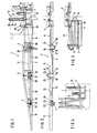
- the spray boom 3 is divided into several sections which are connected to one another by means of the joints 4, 5, 6 and 7.
- the innermost section 8 of the spray boom 3 is arranged on the support frame 2 with the joint 4, the pivot axis of which extends approximately in the direction of travel of the field sprayer.
- the sections 9, 10 and 11 of the spray boom 3 adjoining the innermost section 8 can each be pivoted about upright axes.
- the spray boom 3 shown in FIGS. 1 and 2 is in its extended position, which corresponds to the working position.
- the sprayer boom 3 is in a folded position, via the position shown in FIG. 3 into that shown in FIG. 4 folded to bring position that corresponds to the transport position. This is done via a remote control device designed as a cable control.
- the remote control device designed as a cable control 12 has the folding rope 13 and the folding rope 14.
- the folding rope 13 and the folding rope 14 are each fixed at a distance from the joint 7 to the outermost section 11 of the sprayer boom 3.
- the folding rope 13 and the folding rope 14 are attached to the support frame 2.
- the respective folding rope 13 or the respective folding rope 14 of the two sides of the sprayer boom 3 can be connected to one another.
- the operating devices of the cable control 12, which are designed as folding cylinders 15 and folding cylinders 16, are arranged on the support frame 2.
- the folding cylinder 15 and the folding cylinder 16 are designed as single-acting hydraulic cylinders.
- Rope guiding elements are arranged between the individual gates 8, 9, 10 and 11 of the sprayer boom 3, which hold the ropes 13 and 14 at a distance from the pivot axis of the respective joints 4, 5, 6 and 7.
- the arm 17 projecting upwards above the joint 4 is arranged above the joint 4.
- This arm 17 has at its upper end the rope guide element designed as a rope pulley 18.
- This pulley 18 is freely rotatably mounted on the arm 17.
- the two small rope pulleys 20 for deflecting the fold-out rope 16 are arranged on the sections 8 and 9 of the spray boom 3 in the region of the joint 5. These pulleys 20 are also freely rotatable arranged. Between the sections 9 and 10, the two rope guide elements designed as rope pulleys 21 are freely rotatable on the hinge pin of the hinge 6. Between the individual sections 10 and 11, the rope guiding elements designed as rope pulleys 22 and 23 are freely rotatable on the hinge pin of the hinge 7.
- the folding rope 13 is attached to the outermost portion 11 of the sprayer boom 3.
- the folding rope 13 is then guided around the large rope pulley 23, which is mounted on the hinge pin of the hinge 7.
- the folding rope 13 is then guided around the small rope pulley 24, which is freely rotatable in the outer area of the section 10.
- the folding rope 13 is then guided around the small rope pulley 25, which is freely rotatably mounted in the inner region of the section 10 of the spray boom 3.
- the folding rope 13 is guided around the lower roller 21.
- the folding rope 13 is guided around by the rope pulley 26, which is freely rotatably mounted on the section 9 in the outer region.
- the folding rope 13 is guided around the roller 27, which is freely rotatably mounted on the inner region of the section 9, before being guided around the roller 19 and the rope roller 28, which is arranged on the inner region of the section 8 in a freely rotatable manner.
- the folding rope 13 is guided around the roller 29, which is arranged in the vicinity of the joint 4 and is freely rotatably supported, before the folding rope 13 is guided around the rope roller 18.
- the folding rope 13 is then deflected around the rope pulley 30 arranged on the support frame 2. After the rope pulley 30, the folding rope 13 is guided over the deflection roller 31 arranged on the folding cylinder 15 and fastened to the support frame 2.
- the fold-out rope 13 is at a distance from the joint 7 attached to the outer portion 11. While the linkage is being folded in, the pull-out cable 14 is placed around the small cable pulley 22. Before the fold-out cable 14 is mounted on the cable pulley 32, which is freely rotatable in the inner region of section 10, the tension spring 33 is arranged in the fold-out cable 14. Furthermore, the fold-out rope 14 is guided over the rope pulley 34 arranged in the outer region of the section 9. When the sprayer boom 3 is folded in, the fold-out rope 14 lies in the region of the joint 6 around the lower pulley 21, which is arranged on the hinge pin of the joint 6. Furthermore, the fold-out rope 14 is guided in the wrong way over the rope pulleys 35 and 36.
- the cable pulley 34 is arranged in the inner region of the section 9, while the cable pulley 35 is freely rotatably mounted in the outer region of the section 8.
- the folding rope 14 which is guided in a pulley-like manner over the rollers 34 and 35, lies around the upper three cable rollers 19, which are arranged on the articulation pin of the articulation 5.
- the folding rope 14 is guided around the rope pulley 37, which is freely rotatably mounted on the support frame 2.
- the fold-out cable 14 is guided around the cable pulley 38 rotatably mounted on the fold-out cylinder 16 and fastened at its end to the support frame 2.
- the folding rope 13 is located on the side of the respective joint 5, 6 and 7 to which the mutually adjacent sections 8, 9, 10 and 11 can be folded together, while the folding rope 14 is located on the other side of the joints 5, 6 , and 7 is located.
- the folding ropes 13 and the folding ropes 14 are each effective in opposite directions to one another. Due to the differently sized rollers 22, 23, 21 and the pulley-like cable deflection in the area of the joint 5, the fold-out moments can be built up from the inside out while the folding moments can be built up from the outside to the inside.
- the sprayer booms are folded in or out as follows:
- the folding cylinder 13 connected to the tractor hydraulic system is extended via a hydraulic operating lever. Extending the folding cylinder 13 shortens the folding rope in the area of the sprayer boom 3.
- the sections 11 are folded back 180 ° to the section 10 of the distributor linkage 3. If the section 11 is folded up to the respective section 10, the sections 10 and 11 are folded together forward by 108 ° to the section 9 of the sprayer boom 3. When the section 10 with the section 11 abuts the section 9 of the sprayer boom 3, the sections 9, 10 and 11 are folded back together around the joint 9 to the section 8 of the sprayer boom 3.
- section 9 now comes to rest on the section 8 of the spray boom 3, and so the sections 8, 9, 10 and 11 form a compact package, as shown in FIG. 3, will this package of sections 8, 9, 10 and 11 folded from the position shown in FIG. 3 into the position shown in FIG. 4.
- the folding ropes 13 and the folding ropes 14 are guided in such a way that the two sections of the sprayer boom 3 located at the side of the field sprayer are simultaneously folded up.
- the fold-out cylinder 14 connected to the tractor hydraulic system is pressurized via a hydraulic valve.
- the pull-out cable 14 is pulled.
- pulling on the folding rope 13 is carried out over the boom 11, on which the folding and unfolding cables are fastened together, so that the folding cylinder 15 is compressed.
- the spray boom 3 is first pivoted into the position shown in FIG. 3 about the pivot axis extending through the joint 4. Then the sections 9, 10 and 11 of the sprayer boom pivot about the joint 5 by 180 ° into a position which is in the extension of the section 8 of the sprayer boom 3.
- section 9 is an extension of section 8
- sections 10 and 11 fold about hinge 6 by 180 ° into a position which is an extension of sections 8 and 9 of the sprayer boom.
- the section 11 then folds about the joint 7 into the position shown in FIG. 2.
- the spray boom 3 is in the working position.
Landscapes
- Life Sciences & Earth Sciences (AREA)
- Engineering & Computer Science (AREA)
- Insects & Arthropods (AREA)
- Pest Control & Pesticides (AREA)
- Wood Science & Technology (AREA)
- Zoology (AREA)
- Environmental Sciences (AREA)
- Catching Or Destruction (AREA)
- Special Spraying Apparatus (AREA)
Applications Claiming Priority (2)
| Application Number | Priority Date | Filing Date | Title |
|---|---|---|---|
| DE3541130 | 1985-11-21 | ||
| DE19853541130 DE3541130A1 (de) | 1985-11-21 | 1985-11-21 | Landwirtschaftliche feldspritze mit einem spritzgestaenge |
Publications (3)
| Publication Number | Publication Date |
|---|---|
| EP0224166A2 true EP0224166A2 (fr) | 1987-06-03 |
| EP0224166A3 EP0224166A3 (en) | 1988-10-12 |
| EP0224166B1 EP0224166B1 (fr) | 1991-05-29 |
Family
ID=6286445
Family Applications (1)
| Application Number | Title | Priority Date | Filing Date |
|---|---|---|---|
| EP86115921A Expired - Lifetime EP0224166B1 (fr) | 1985-11-21 | 1986-11-17 | Rampe de pulvérisation pour un pulvérisateur agricole |
Country Status (2)
| Country | Link |
|---|---|
| EP (1) | EP0224166B1 (fr) |
| DE (2) | DE3541130A1 (fr) |
Cited By (3)
| Publication number | Priority date | Publication date | Assignee | Title |
|---|---|---|---|---|
| US7431221B2 (en) | 2005-05-16 | 2008-10-07 | Cnh Canada, Ltd. | Lock assembly for a multiple stage folding boom assembly |
| CN101837330A (zh) * | 2010-05-17 | 2010-09-22 | 华南农业大学 | 基于斜拉绳式支撑的喷雾机喷杆机构 |
| AU2015210476B2 (en) * | 2014-08-11 | 2019-06-13 | Deere & Company | Segmented boom system for work vehicle |
Families Citing this family (3)
| Publication number | Priority date | Publication date | Assignee | Title |
|---|---|---|---|---|
| US5178328A (en) * | 1991-12-18 | 1993-01-12 | The Broyhill Company | Folding boom for agricultural sprayers |
| AU719303B2 (en) * | 1998-09-14 | 2000-05-04 | Bent Baek | Agriculture/viticulture sprayer |
| AT521966B1 (de) | 2019-02-15 | 2020-07-15 | Georg Unger Dr | Mobile Bewässerungsanlage |
Citations (8)
| Publication number | Priority date | Publication date | Assignee | Title |
|---|---|---|---|---|
| US3055594A (en) * | 1960-01-04 | 1962-09-25 | Burg Mfg Company | Boom type spraying means |
| DE1859848U (de) * | 1962-06-09 | 1962-10-11 | Otto Quentin | Spritzvorrichtung. |
| FR1455965A (fr) * | 1964-07-29 | 1966-05-20 | H J Hoegen Dijkhof G M B H | Dispositif monté sur un véhicule pour faire des pulvérisations d'insecticides |
| FR2450035A1 (fr) * | 1979-02-28 | 1980-09-26 | Mahe Jean | Traceur et appareil de traitement en localise pour travaux de grandes largeurs en agriculture |
| FR2460438A2 (fr) * | 1978-12-11 | 1981-01-23 | Evrard Ets | Dispositif pour la stabilite de rampes de pulverisation |
| DE3025175B1 (de) * | 1980-07-03 | 1981-02-12 | Amazonen Werke Dreyer H | Verteilmaschine mit Auslegern |
| FR2505681A1 (fr) * | 1981-05-14 | 1982-11-19 | Rau Gmbh Maschf | Appareil de pulverisation |
| FR2560533A1 (fr) * | 1984-03-01 | 1985-09-06 | Evrard Ets | Perfectionnements aux rampes de pulverisation agricole repliables |
-
1985
- 1985-11-21 DE DE19853541130 patent/DE3541130A1/de not_active Withdrawn
-
1986
- 1986-11-17 EP EP86115921A patent/EP0224166B1/fr not_active Expired - Lifetime
- 1986-11-17 DE DE8686115921T patent/DE3679512D1/de not_active Expired - Lifetime
Patent Citations (8)
| Publication number | Priority date | Publication date | Assignee | Title |
|---|---|---|---|---|
| US3055594A (en) * | 1960-01-04 | 1962-09-25 | Burg Mfg Company | Boom type spraying means |
| DE1859848U (de) * | 1962-06-09 | 1962-10-11 | Otto Quentin | Spritzvorrichtung. |
| FR1455965A (fr) * | 1964-07-29 | 1966-05-20 | H J Hoegen Dijkhof G M B H | Dispositif monté sur un véhicule pour faire des pulvérisations d'insecticides |
| FR2460438A2 (fr) * | 1978-12-11 | 1981-01-23 | Evrard Ets | Dispositif pour la stabilite de rampes de pulverisation |
| FR2450035A1 (fr) * | 1979-02-28 | 1980-09-26 | Mahe Jean | Traceur et appareil de traitement en localise pour travaux de grandes largeurs en agriculture |
| DE3025175B1 (de) * | 1980-07-03 | 1981-02-12 | Amazonen Werke Dreyer H | Verteilmaschine mit Auslegern |
| FR2505681A1 (fr) * | 1981-05-14 | 1982-11-19 | Rau Gmbh Maschf | Appareil de pulverisation |
| FR2560533A1 (fr) * | 1984-03-01 | 1985-09-06 | Evrard Ets | Perfectionnements aux rampes de pulverisation agricole repliables |
Cited By (5)
| Publication number | Priority date | Publication date | Assignee | Title |
|---|---|---|---|---|
| US7431221B2 (en) | 2005-05-16 | 2008-10-07 | Cnh Canada, Ltd. | Lock assembly for a multiple stage folding boom assembly |
| CN101837330A (zh) * | 2010-05-17 | 2010-09-22 | 华南农业大学 | 基于斜拉绳式支撑的喷雾机喷杆机构 |
| AU2015210476B2 (en) * | 2014-08-11 | 2019-06-13 | Deere & Company | Segmented boom system for work vehicle |
| AU2015210476B8 (en) * | 2014-08-11 | 2019-06-27 | Deere & Company | Segmented boom system for work vehicle |
| AU2015210476A8 (en) * | 2014-08-11 | 2019-06-27 | Deere & Company | Segmented boom system for work vehicle |
Also Published As
| Publication number | Publication date |
|---|---|
| DE3541130A1 (de) | 1987-05-27 |
| EP0224166B1 (fr) | 1991-05-29 |
| DE3679512D1 (de) | 1991-07-04 |
| EP0224166A3 (en) | 1988-10-12 |
Similar Documents
| Publication | Publication Date | Title |
|---|---|---|
| DE3925150C2 (fr) | ||
| DE2713270C3 (de) | Tragbalken für landwirtschaftliche Geräte mit wenigstens einem verschwenkbaren Balkenteil | |
| DE60127771T2 (de) | Brückenuntersichtvorrichtung mit Querverbindung zwischen Turm und Fahrzeugrahmen | |
| EP0056118A1 (fr) | Appareil ou châssis repliable pour machines agricoles | |
| DE1482373A1 (de) | An ein Fahrzeug anbaubare Vorrichtung zum Verspruehen von Schaedlingsbekaempfungsmitteln | |
| EP1770050B1 (fr) | Grue repliable | |
| DE1481873A1 (de) | Lasthebevorrichtung | |
| EP0317891A2 (fr) | Appareil de lutte contre l'incendie dans des endroits de grande hauteur | |
| DE2817650C2 (fr) | ||
| DE2834646A1 (de) | Kettenschaltung mit gangvorwahl | |
| EP0224166B1 (fr) | Rampe de pulvérisation pour un pulvérisateur agricole | |
| DE4413444A1 (de) | Laderampe für Kraftfahrzeuge | |
| DE3921291A1 (de) | Landwirtschaftliche feldspritze | |
| DE60007488T2 (de) | Zusammenklappvorrichtung eines Kranauslegers mit ineinandersetzbaren Elementen | |
| DE3419427A1 (de) | Gelenkkran | |
| DE3831186C2 (de) | Heuwerbungsmaschine | |
| DE2445965A1 (de) | Spruehvorrichtung fuer landwirtschaftliche zwecke | |
| DE102019104831B3 (de) | Feldspritze mit Zuführmittel zum Eintrag von Dünger oder Pflanzenschutzmitteln unterhalb des Blattwerks von Pflanzen | |
| DE3838936A1 (de) | Verteilereinrichtung fuer haecksler | |
| EP0604681B1 (fr) | Bras de buses pour arroser en particulier des surfaces agricoles | |
| EP0212235A2 (fr) | Appareil de pulvérisation agricole avec une rampe de pulvérisation | |
| DE3932955C1 (en) | Coating device for silk-screen printing - incorporates guide and tipping device for ink trough | |
| DE3811506C2 (fr) | ||
| DE10040056A1 (de) | Klapprahmen | |
| DE6602991U (de) | Lastdrueckgeraet, insbesondere fuer hubkarren |
Legal Events
| Date | Code | Title | Description |
|---|---|---|---|
| PUAI | Public reference made under article 153(3) epc to a published international application that has entered the european phase |
Free format text: ORIGINAL CODE: 0009012 |
|
| AK | Designated contracting states |
Kind code of ref document: A2 Designated state(s): BE DE FR GB NL |
|
| PUAL | Search report despatched |
Free format text: ORIGINAL CODE: 0009013 |
|
| AK | Designated contracting states |
Kind code of ref document: A3 Designated state(s): BE DE FR GB NL |
|
| 17P | Request for examination filed |
Effective date: 19880830 |
|
| 17Q | First examination report despatched |
Effective date: 19900727 |
|
| GRAA | (expected) grant |
Free format text: ORIGINAL CODE: 0009210 |
|
| AK | Designated contracting states |
Kind code of ref document: B1 Designated state(s): BE DE FR GB NL |
|
| ET | Fr: translation filed | ||
| REF | Corresponds to: |
Ref document number: 3679512 Country of ref document: DE Date of ref document: 19910704 |
|
| GBT | Gb: translation of ep patent filed (gb section 77(6)(a)/1977) | ||
| PGFP | Annual fee paid to national office [announced via postgrant information from national office to epo] |
Ref country code: BE Payment date: 19911112 Year of fee payment: 6 |
|
| PLBE | No opposition filed within time limit |
Free format text: ORIGINAL CODE: 0009261 |
|
| STAA | Information on the status of an ep patent application or granted ep patent |
Free format text: STATUS: NO OPPOSITION FILED WITHIN TIME LIMIT |
|
| 26N | No opposition filed | ||
| PGFP | Annual fee paid to national office [announced via postgrant information from national office to epo] |
Ref country code: GB Payment date: 19920821 Year of fee payment: 7 |
|
| PGFP | Annual fee paid to national office [announced via postgrant information from national office to epo] |
Ref country code: FR Payment date: 19921127 Year of fee payment: 7 |
|
| PG25 | Lapsed in a contracting state [announced via postgrant information from national office to epo] |
Ref country code: BE Effective date: 19921130 |
|
| PGFP | Annual fee paid to national office [announced via postgrant information from national office to epo] |
Ref country code: NL Payment date: 19921130 Year of fee payment: 7 |
|
| BERE | Be: lapsed |
Owner name: AMAZONEN-WERKE H. DREYER G.M.B.H. & CO. K.G. Effective date: 19921130 |
|
| PG25 | Lapsed in a contracting state [announced via postgrant information from national office to epo] |
Ref country code: GB Effective date: 19931117 |
|
| PGFP | Annual fee paid to national office [announced via postgrant information from national office to epo] |
Ref country code: DE Payment date: 19931124 Year of fee payment: 8 |
|
| PG25 | Lapsed in a contracting state [announced via postgrant information from national office to epo] |
Ref country code: NL Effective date: 19940601 |
|
| GBPC | Gb: european patent ceased through non-payment of renewal fee |
Effective date: 19931117 |
|
| NLV4 | Nl: lapsed or anulled due to non-payment of the annual fee | ||
| PG25 | Lapsed in a contracting state [announced via postgrant information from national office to epo] |
Ref country code: FR Effective date: 19940729 |
|
| REG | Reference to a national code |
Ref country code: FR Ref legal event code: ST |
|
| PG25 | Lapsed in a contracting state [announced via postgrant information from national office to epo] |
Ref country code: DE Effective date: 19950801 |