EP0222588B1 - Alimentateur pour la feuille de dessus - Google Patents
Alimentateur pour la feuille de dessus Download PDFInfo
- Publication number
- EP0222588B1 EP0222588B1 EP86308613A EP86308613A EP0222588B1 EP 0222588 B1 EP0222588 B1 EP 0222588B1 EP 86308613 A EP86308613 A EP 86308613A EP 86308613 A EP86308613 A EP 86308613A EP 0222588 B1 EP0222588 B1 EP 0222588B1
- Authority
- EP
- European Patent Office
- Prior art keywords
- sheet
- stack
- sheets
- vacuum
- jets
- Prior art date
- Legal status (The legal status is an assumption and is not a legal conclusion. Google has not performed a legal analysis and makes no representation as to the accuracy of the status listed.)
- Expired - Lifetime
Links
Images


Classifications
-
- B—PERFORMING OPERATIONS; TRANSPORTING
- B65—CONVEYING; PACKING; STORING; HANDLING THIN OR FILAMENTARY MATERIAL
- B65H—HANDLING THIN OR FILAMENTARY MATERIAL, e.g. SHEETS, WEBS, CABLES
- B65H3/00—Separating articles from piles
- B65H3/46—Supplementary devices or measures to assist separation or prevent double feed
- B65H3/48—Air blast acting on edges of, or under, articles
-
- B—PERFORMING OPERATIONS; TRANSPORTING
- B65—CONVEYING; PACKING; STORING; HANDLING THIN OR FILAMENTARY MATERIAL
- B65H—HANDLING THIN OR FILAMENTARY MATERIAL, e.g. SHEETS, WEBS, CABLES
- B65H3/00—Separating articles from piles
- B65H3/08—Separating articles from piles using pneumatic force
- B65H3/12—Suction bands, belts, or tables moving relatively to the pile
- B65H3/124—Suction bands or belts
- B65H3/128—Suction bands or belts separating from the top of pile
Definitions
- This invention relates to an improved sheet feeding apparatus, particularly for use in an electrophotographic printing machine.
- One of the sheet feeders best known for high speed operation is the top vacuum corrugation feeder with front air knife.
- a vacuum plenum with a plurality of friction belts arranged to run over the vacuum plenum is placed at the top of a stack of sheets in a supply tray.
- an air knife is used to inject air into the stack to separate the top sheet from the remainder of the stack.
- air is injected by the air knife toward the stack to separate the top sheet, the vacuum pulls the separated sheet up and acquires it.
- the belt transport drives the sheet forward off the stack of sheets. In this configuration, separation of the next sheet cannot take place until the top sheet has cleared the stack.
- the valve is actuated, establishing a flow and hence a negative pressure field over the stack top or bottom if a bottom vacuum corrugation feeder is employed.
- This field causes the movement of the top sheet(s) to the vacuum feedhead where the sheet is then transported to the takeaway rolls. Once the sheet feed edge is under control of the takeaway rolls, the vacuum is shut off. The trail edge of this sheet exiting the feedhead area is the criteria for again activating the vacuum valve for the next feeding.
- U.S. Patent 2,979,329 (Cunningham) describes a sheet feeding mechanism useful for both top and bottom feeding of sheets wherein an oscillating vacuum chamber is used to acquire and transport a sheet to be fed. In addition, an air blast is directed to the leading edge of a stack of sheets from which the sheet is to be separated and fed to assist in separating the sheets from the stack.
- U.S. Patent 3,424,453(Halbert) illustrates a vacuum sheet separator feeder with an air knife wherein a plurality of feed belts with holes are transported about a vacuum plenum and pressurized air is delivered to the leading edge of the stack of sheets. This is a bottom sheet feeder.
- U.S. Patent 2,895,552 (Pomper et al.) illustrates a vacuum belt transport and stacking device wherein sheets which have been cut from a web are transported from the sheet supply to a sheet stacking tray. Flexible belts perforated at intervals are used to pick up the leading edge of the sheet and release the sheet over the pile for stacking.
- U.S. Patent 4,157,177(Strecker) illustrates another sheet stacker wherein a first belt conveyor delivers sheets in a shingled fashion and the lower reach of a second perforated belt conveyor which is above the top of the stacking magazine attracts the leading edge of the sheets.
- the device has a slide which limits the effect of perforations depending on the size of the shingled sheet.
- U.S. Patent 4,268,025 (Murayoshi) describes a top sheet feeding apparatus wherein a sheet tray has a vacuum plate above the tray which has a suction hole in its bottom portion. A feed roll in the suction hole transports a sheet to a separating roll and a frictional member in contact with the separating roll.
- U.S. Patent 4,418,905 shows a bottom vacuum corrugation feeding system.
- U.S. Patent 4,451,028 discloses a top feed vacuum corrugation feeding system that employs front and back vacuum plenums.
- U.S. Patent 3,182,998 (Peterson) is directed to a conveyor device that includes a belt comprising diamond shaped rubber suction cups.
- U.S. Patent 3,260,520 (Sugden) is directed to document handling apparatus that employs a vacuum feed system and a vacuum reverse feed belt adapted to separate doublets.
- U.S. Patent 3,614,089 (Van Auken) relates to an automatic document feeder that includes blowers to raise a document up against feed belts for forward transport. Stripper wheels are positioned below the feed belts and adapted to bear against the lower surface of the lowermost document and force it back into the document stack.
- IBM Technical Disclosure Bulletin entitled "Document Feeder and Separator", Vo. 6, No. 2, page 32, 1963 discloses a perforated belt that has a vacuum applied through the perforations in the belt in order to lift documents from a stack for transport.
- the belt extends over the center of the document stack.
- a sheet feeding apparatus for feeding sheets from a stack, comprising a sheet stack support tray, feedhead means including a vacuum plenum chamber positioned adjacent the front of a stack of sheets when sheets are placed in the tray with the vacuum chamber having a negative pressure applied thereto during a feed cycle, said vacuum plenum chamber having a sheet corrugation means mounted in the centre of its surface directed towards the stack and perforated feed belt means associated with said vacuum plenum chamber to transport the sheets acquired by said vacuum plenum chamber in a forward direction out of the stack support tray; and air knife means positioned immediately adjacent the front of said stack of sheets, said air knife means including jets for applying a positive pressure to the sheet stack in order to separate the uppermost sheet from the rest of the stack; characterized in that said feed belt means includes a knurled surface to increase the coupling between a sheet and said vacuum belt means, and in that the apparatus includes fang gate means adapted to prevent multi feeding of sheets.
- the present invention provides an improved top sheet separator feeder capable of operating at high speed and independent of sheet material properties.
- the air knife means includes fluffer jets for fluffing sheets in the stack, vectored auxiliary fluffer jets for assisting in fluffing downcurled sheets in the stack, and a converging slot jet for separating a sheet to be transported from the rest of the stack.
- the feeder includes critical enablers for fluffing the sheets in order to improve the feeding of downcurled, stiff sheets.
- a sheet separator feeder in accordance with the invention has an improved vacuum feed mechanism belt that enhances sheet acquisition by effectively enlarging the vacuum area, and thereby also increasing the sheet drive out force of the feed belt.
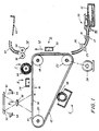
- FIG. 1 is a schematic elevational view of an electrophotographic printing machine incorporating the present invention therein.
- Figure 2 is an enlarged partial cross-sectional view of the exemplary feeder in Figure 1 which is employed in accordance with the present invention.
- Figure 3 is a partial front end view of the paper tray shown in Figure 2.
- Figure 4 is a front end view of the air knife in accordance with the present invention.
- Figure 5 is a sectional plan view of the air knife shown in Figure 4.
- Figure 6 is a side view of the air knife shown in Figure 4 taken along line 6 - 6 of Figure 4.
- Figures 7A and 7B are respective plan and side view illustrations of the converging stream (Figure 7A) and expanding air streams (Figure 78) which result from converging air nozzles in the air knife of Figure 4.
- FIG. 1 schematically depicts the various components of an illustrative electrophotographic printing machine incorporating the sheet feeding apparatus of the present invention therein. It will become evident from the following discussion that the sheet feeding system disclosed herein is equally well suited for use in a wide variety of devices and is not necessarily limited to its application to the particular embodiment shown herein. For example, the apparatus of the present invention may be readily employed in non-xerographic environments and substrate transportation in general.
- the electrophotographic printing machine employs a belt 10 having a photoconductive surface 12 deposited on a conductive substrate 14.
- photoconductive surface 12 is made from an aluminum alloy.
- Belt 10 moves in the direction of arrow 16 to advance successive portions of photoconductive surface 12 sequentially through the various processing stations disposed about the path of movement thereof.
- Belt 10 is entrained around stripper roller 18, tension roller 20, and drive roller 22.
- Drive roller 22 is mounted rotatably in engagement with belt 10. Roller 22 is coupled to a suitable means such as motor 24 through a belt drive. Motor 24 rotates roller 22 to advance belt 10 in the direction of arrow 16.
- Drive roller 22 includes a pair of opposed spaced flanges or edge guides (not shown). Preferably, the edge guides are circular members of flanges.
- Belt 10 is maintained in tension by a pair of springs (not shown), resiliently urging tension roller 20 against belt 10 with the desired spring force.
- Both stripping roller 18 and tension roller 20 are mounted rotatably. These rollers are idlers which rotate freely as belt 10 moves in the direction of arrow 16.
- a corona generating device indicated generally by the reference numeral 28, charges photoconductive surface 12 of the belt 10 to a relatively high, substantially uniform potential.
- the charged portion of photoconductive surface 12 is advanced through exposure station B.
- an original document 30 is positioned face down upon transparent platen 32.
- Lamps 34 flash light rays onto original document 30.
- the light rays reflected from the original document 30 are transmitted through lens 36 from a light image thereof.
- the light image is projected onto the charged portion of the photoconductive surface 12 to selectively dissipate the charge thereon. This records an electrostatic latent image on photoconductive surface 12 which corresponds to the information areas contained within original document 30.
- belt 10 advances the electrostatic latent image recorded on photoconductive surface 12 to development station C.
- a magnetic brush developer roller 38 advances a developer mix into contact with the electrostatic latent image.
- the latent image attracts the toner particles from the carrier granules forming a toner powder image on photoconductive surface 12 of belt 10.
- Belt 10 then advances the toner powder image to transfer station D.
- a sheet of support material is moved into contact with the toner powder image.
- the sheet support material is advanced toward transfer station D by top vacuum corrugation feeder 70.
- the feeder includes an air knife 80 which floats a sheet 31 up to where it is grabbed by the suction force from vacuum plenum 75.
- a perforated feed belt 71 then forwards the now separated sheet for further processing, i.e., the sheet is directed through rollers 17, 19, 23, and 26 into contact with the photoconductive surface 12 of belt 10 in a timed sequence by suitable conventional means so that the toner powder image developed thereon synchronously contacts the advancing sheet of support material at transfer station D.
- Transfer station D includes a corona generating device 50 which sprays ions onto the backside of a sheet passing through the station. This attracts the toner powder image from the photoconductive surface 12 to the sheet and provides a normal force which causes photoconductive surface 12 to take over transport of the advancing sheet of support material. After transfer, the sheet continues to move in the direction of arrow 52 onto a conveyor (not shown) which advances the sheet to fusing station E.
- Fusing station E includes a fuser assembly, indicated generally by the reference number 54, which permanently affixes the transferred toner powder image to the substrate.
- fuser assembly 54 includes a heated fuser roller 56 and a backup roller 58.
- a sheet passes between fuser roller 56 and backup roller 58 with the toner powder image contacting fuser roller 56. In this manner, the toner powder image is permanently affixed to the sheet.
- chute 60 guides the advancing sheet to catch tray 62 for removal from the printing machine by the operator.
- Cleaning station F includes a rotatably mounted brush 64 in contact with the photoconductive surface 12. The particles are cleaned from photoconductive surface 12 by the rotation of brush 64 in contact therewith. Subsequent to cleaning, a discharge lamp (not shown) floods photoconductive surface 12 with light to dissipate any residual electrostatic charge remaining thereon prior to the charging thereof for the next successive image cycle.
- Figures 2 and 3 show a system employing the present invention in a copy sheet feeding mode.
- the sheet feeder may be mounted for feeding document sheets to the platen of a printing machine.
- the sheet feeder is provided with a conventional elevator mechanism 41 for raising and lowering either tray 40 or a platform 42 within tray 40.
- a drive motor is actuated to move the sheet stack support platform 42 vertically by a stack height sensor positioned above the rear of the stack when the level of sheets relative to the sensor falls below a first predetermined level.
- the drive motor is deactuated by the stack height sensor when the level of the sheets relative to the sensor is above a predetermined level. In this way, the level of the top sheet in the stack of sheets may be maintained within relatively narrow limits to assure proper sheet separation, acquisition and feeding.
- Vacuum corrugation feeder 70 and a vacuum plenum 75 are positioned over the front end of a tray 40 having copy sheets 31 stacked therein.
- Belts 71 are entrained around drive rollers 24 as well as plenum 75. Belts 71 could be made into a single belt if desired.
- Perforations 72 in the belts allow a suitable vacuum source (not shown) to apply a vacuum through plenum 75 and belts 71 to acquire sheets 31 from stack 13.
- Air knife 80 applies a positive pressure to the front of stack 13 to separate the top sheet in the stack and enhance its acquisition by vacuum plenum 75.
- Corrugation rail 76 is attached or molded into the underside and center of plenum 75 and causes sheets acquired by the vacuum plenum to bend during the corrugation so that if a second sheet is still sticking to the sheet having been acquired by the vacuum plenum, the corrugation will cause the second sheet to detack and fall back into the tray.
- a sheet captured on belts 71 is forwarded through baffles 9 and 15 and into forwarding drive rollers 17 and 19 for transport to transfer station D.
- a pair of restriction members 33 and 35 are attached to the upper front end of tray 40 and serve to inhibit all sheets other than sheet 1 from leaving the tray. It is also possible to place these restriction members or fangs on the air knife instead of the tray.
- vacuum plenum 75 is preferably equipped with a negative pressure source that is ON continuously during the feed cycle, with the only criterion for sheet feeding being that the motion of vacuum feedhead 70 is ceased prior to the trail edge of the acquired sheet exposing all of the vacuum ports. The next sheet is then acquired in a "traveling wave" fashion as shown in Figure 2.
- This improved feeding scheme affords a reduction in noise due to the elimination of the valve associated with cutting the vacuum means ON and OFF.
- increased reliability/decreased minimum feed speed is obtained, i.e., for given minimum required sheet acquisition and separation times the removal of the valve from the vacuum system allows increased available acquisition/separation time per feed cycle and/or lower required minimum feed speeds.
- valveless vacuum feedhead of the present invention is equally adaptable to either bottom or top vacuum corrugation feeders. If one desired, the negative pressure source could be valved, however, in this situation the vacuum valve is turned OFF as soon as the fed sheet arrives at the take away roll and is then turned back ON when the trail edge of the fed sheet passes the lead edge of the stack.
- the ripple in sheet 2 makes for a more reliable feeder since the concavity of the sheet caused by continuously operating vacuum plenum 75 will increase the unbuckling of sheet 3 from sheet 2.
- Sheet 3 will have a chance to settle down against the stack before sheet 2 is fed since air knife 80 has been turned off.
- Belts 71 are stopped just before sheet 1 uncovers the vacuum plenum completely in order to enhance the dropping of any sheets that are tacked to sheet 2 back down upon the stack and to feed the sheets in time with images produced on the photoreceptor.
- belts 71 are turned in a clockwise direction to feed sheet 2.
- Knife 80 is also turned ON and applies air pressure to the front of the stack to insure separation of sheet 2 from any other sheets and assist the vacuum plenum in lifting the front end of the sheet up against corrugation rail 76 which is an additional means of insuring against multi-sheet feeding. Knife 80 may be either left continuously “ON” or valved “ON” - “OFF” during appropriate times in the feed cycle. Lightweight flimsy sheet feeding is enhanced with this method of feeding since sheet 2 is easily adhered to the vacuum plenum while sheet 1 is being fed by transport rollers 17 and 19. Also, gravity will conform the front and rear portions of sheet 2 against the stack while the concavity produced in the sheet by the vacuum plenum remains.
- a plurality of feed belts 71 supported for movement on rollers.
- a vacuum plenum 75 Spaced within the run of belts 71 there is provided a vacuum plenum 75 having an opening therein adapted for cooperation with perforations 72 in the belts to provide a vacuum for pulling the top sheet in the stack onto the belts 71.
- the plenum is provided with a centrally located projecting portion 76 so that upon capture of the top sheet in the stack by the belts a corrugation will be produced in the sheet.
- the sheet is corrugated in a double valley configuration.
- the flat surfaces of the vacuum belts on each side of the projecting portion of the vacuum plenum generates a region of maximum stress in the sheet which varies with the beam strength of the sheet.
- the second sheet resists the corrugation action, thus gaps are opened between sheets 1 and 2 which extend to their lead edges.
- the gaps and channels reduce the vacuum levels between sheets 1 and 2 due to porosity in sheet 1 and provide for entry of the separating air flow of the air knife 80.
- valving and controls it is desirable to provide a delay between the time the vacuum is applied to pull the document up to the feed belts and the start up of the belts to assure that the top sheet in the stack is captured before belt movement commences and to allow time for the air knife to separate sheet 1 from sheet 2 or any other sheets that were pulled up.
- vacuum feed belts and transport belts are flat, smooth, usually elastomeric, and usually with prepunched holes. These holes, coupled with openings to a vacuum plenum between the belts, serve to transmit a negative pressure to the transported sheet material.
- This negative pressure causes a normal force to exist between the sheet material and the transport belts with the drive force between the sheet material and belts being proportional to the normal force.
- the problem with these conventional belts is that the negative pressure field is not uniform between the sheet material and the belts once the sheet material is acquired due to sheet porosity effects.
- the pressure is very highly negative (sealed post pressure) in the near regions of vacuum holes in the belts but increases quickly to atmospheric pressure as the immediate area of holes is left.
- belts 71 are provided as an answer to this problem and improves the coupling between the sheet materials and the vacuum belts by roughening or knurling the elastomer surface of the belts. As a result, a more uniform vacuum force is applied over the entire sheet area compared to the force localized to the regions of the belt holes with a smooth belt. In effect, roughening the surface of the belts, and using a diamond knurl pattern, allows a more uniform, higher average pressure differential to exist across the sheet material for the same heretofore used sealed port pressure, which increases the drive force.
- the improved air knife 80 shown in greater detail in Figures 4 - 6 contains fluffer jets 81, vectored auxiliary fluffer jets 96 and 97 and a converging slot jet 84.
- the pressurized air plenum 83 and converging slot jet 84 includes an array of separated air nozzles 90 - 95 that are angled upward with respect to the front edge of the sheet stack.
- the center two nozzles 92 and 93 essentially direct air streams in slightly inwardly directed parallel air streams while the two end sets of nozzles 90, 91 and 94, 95 are angled toward the center of the parallel air streams of nozzles 92 and 93 and provide converging streams of air.
- the end nozzles 90 and 91 are slanted at angles of 37 and 54 degrees, respectively.
- nozzles 94 and 95 that is, nozzle 94 at 54 degrees and nozzle 95 at 37 degrees are slanted inward toward the center of the nozzle group.
- Nozzles 92 and 93 are angled to direct the main air stream at an angle of 68 degrees respectively.
- Nozzles 90 through 95 are all arranged in a plane so that the air stream which emerges from the nozzles is essentially planar. As the streams produced from nozzles 90 through 95 emerges from the ends of the nozzles they tend to converge laterally toward the center of the nozzle grouping. This may be more graphically illustrated in Figure 7A which shows the streams converging laterally.
- pre-separating sheet from one another in a stack is essential in the obtainment of suitable feeding reliability for high volume feeders.
- Stress cases such as downcurled stiff sheets, however, show a large resistance to "fluffing" when acted upon by sheet separation jets 81 which are essentially perpendicular to the stack lead edge.
- a cure to this resistance to "fluffing” is incorporated into air knife 80 such that the reliability is greatly enhanced in addition to "fluffing" of the sheets being accomplished and this is by including vectored auxiliary fluffer jets at prescribed angles with reference to the stack edge and located in a manner with reference to the existing main fluffer jets. These additional angled vectored auxiliary fluffer jets 96 and 97 are critical in the proper feeding of stressful paper.
- a vacuum corrugation feeder that includes a unique air knife assembly, a feedhed assembly that consists of a vacuum plenum combined with knurled feedbelts and a sheet corrugator and a fang gate that aids in multifeed prevention. Operation of the vacuum plenum such that it is ON all the time without valving allows faster throughput of copy sheets or documents through the apparatus.
Landscapes
- Engineering & Computer Science (AREA)
- Mechanical Engineering (AREA)
- Sheets, Magazines, And Separation Thereof (AREA)
Claims (7)
- Dispositif d'introduction de feuilles destiné à introduire des feuilles à partir d'une pile, comprenant un plateau (40) de support de la pile de feuilles, un moyen de tête d'introduction (70) comprenant une chambre sous vide (75) placée à proximité de l'avant d'une pile de feuilles lorsque des feuilles sont placées dans le plateau avec la chambre sous vide subissant l'application d'une pression négative pendant un cycle d'introduction, la chambre sous vide comportant un moyen (76) pour onduler les feuilles monté au centre de sa surface dirigée vers l'empilage et un moyen de bande perforée d'introduction (71) associée à la chambre sous vide de manière à acheminer les feuilles acquises par la chambre sous vide dans la direction avant pour les faire sortir du plateau de support de l'empilage; et un moyen de couteau d'air (80) placé à un endroit immédiatement contigu à l'avant de la pile de feuilles, le moyen de couteau d'air comprenant des jets pour appliquer une pression positive à la pile de feuilles de façon à séparer la feuille la plus haute du reste de la pile; caractérisé en ce que le moyen de bande d'introduction comporte une surface molletée afin d'augmenter le couplage entre une feuille et le moyen de bande sous vide, et en ce que le dispositif comprend un moyen de porte de limitation (33, 35) destiné à empêcher les introductions multiples des feuilles.
- Dispositif d'introduction de feuilles selon la revendication 1, dans lequel le moyen de couteau d'air comprend des jets (81) pour donner du bouffant aux feuilles de la pile, des jets auxiliaire vectorisés pour donner du bouffant (96, 97) pour aider à conférer du bouffant aux feuilles de la pile incurvées vers le bas, et un jet convergent (84) de fente pour séparer une feuille devant être acheminée à partir du reste de la pile.
- Dispositif d'introduction de feuilles selon la revendication 1 ou la revendication 2, comprenant un moyen de vide pour appliquer une pression négative continue et uniforme à la chambre sous vide à tout moment pendant l'introduction des feuilles à partir du plateau de support de la pile.
- Dispositif d'introduction de feuilles selon l'une quelconque des revendications précédentes, dans lequel le moyen d'ondulation comprend un rail placé au centre de la surface de la chambre sous vide.
- Dispositif d'introduction de feuilles selon l'une quelconque des revendications précédentes, dans lequel le moyen de bande d'introduction comprend une multitude de bandes individuelles séparées les unes des autres par une quantité prédéterminée.
- Dispositif d'introduction de feuilles selon l'une quelconque des revendications précédentes, dans lequel la surface molletée du moyen de bande d'introduction comprend des parties molletées en élévation ayant la configuration d'un motif en forme de losange de manière à faciliter le passage d'une pression négative sur la surface du moyen de bande d'introduction et donc augmenter le frottement entre le moyen de bande d'introduction et une feuille acheminée du plateau de support de la pile.
- Dispositif d'introduction de feuilles selon la revendication 2, dans lequel les jets donnant du bouffant sont perpendiculaires au bord avant de la pile de feuilles, et les jets convergents de la fente et les jets auxiliaires vectorisés donnant du bouffant sont placés suivant des angles aigus par rapport aux jets de séparation.
Applications Claiming Priority (2)
| Application Number | Priority Date | Filing Date | Title |
|---|---|---|---|
| US795593 | 1985-11-06 | ||
| US06/795,593 US4627605A (en) | 1985-11-06 | 1985-11-06 | Front air knife top vacuum corrugation feeder |
Publications (3)
| Publication Number | Publication Date |
|---|---|
| EP0222588A2 EP0222588A2 (fr) | 1987-05-20 |
| EP0222588A3 EP0222588A3 (en) | 1987-08-19 |
| EP0222588B1 true EP0222588B1 (fr) | 1991-05-02 |
Family
ID=25165938
Family Applications (1)
| Application Number | Title | Priority Date | Filing Date |
|---|---|---|---|
| EP86308613A Expired - Lifetime EP0222588B1 (fr) | 1985-11-06 | 1986-11-05 | Alimentateur pour la feuille de dessus |
Country Status (5)
| Country | Link |
|---|---|
| US (1) | US4627605A (fr) |
| EP (1) | EP0222588B1 (fr) |
| JP (1) | JP2738532B2 (fr) |
| CA (1) | CA1289581C (fr) |
| DE (1) | DE3679030D1 (fr) |
Families Citing this family (24)
| Publication number | Priority date | Publication date | Assignee | Title |
|---|---|---|---|---|
| US4699369A (en) * | 1986-06-27 | 1987-10-13 | Xerox Corporation | Front air knife improvement for a top vacuum corrugation feeder |
| US4768769A (en) * | 1986-12-19 | 1988-09-06 | Xerox Corporation | Low cost rear air knife top vacuum corrugation feeder |
| LU86728A1 (fr) * | 1986-12-30 | 1988-07-14 | Guy Martin | Dispositif de prise de feuilles planes |
| US5071110A (en) * | 1987-12-10 | 1991-12-10 | Xerox Corporation | Vacuum corrugation feeder having an air knife with an elastomeric gate |
| US4887805A (en) * | 1988-03-10 | 1989-12-19 | Xerox Corporation | Top vacuum corrugation feeder |
| JP2934442B2 (ja) * | 1988-09-19 | 1999-08-16 | 株式会社日立製作所 | 紙葉類分離給送装置及び紙葉類分離給送方法 |
| US5190276A (en) * | 1990-03-13 | 1993-03-02 | Sharp Kabushiki Kaisha | Sheet feeding apparatus |
| JP2578238B2 (ja) * | 1990-03-20 | 1997-02-05 | シャープ株式会社 | 最上部シートの給送装置 |
| JP2578237B2 (ja) * | 1990-03-20 | 1997-02-05 | シャープ株式会社 | シートの給送装置 |
| US5052675A (en) * | 1990-06-21 | 1991-10-01 | Xerox Corporation | Top vacuum corrugation feeder with aerodynamic drag separation |
| US5227004A (en) * | 1991-03-15 | 1993-07-13 | Graphic Technology Systems, Inc. | Method and apparatus for producing laminated material |
| US5344133A (en) * | 1993-02-25 | 1994-09-06 | Eastman Kodak Company | Vacuum belt feeder having a positive air pressure separator and method of using a vacuum belt feeder |
| JP3097889B2 (ja) * | 1993-10-01 | 2000-10-10 | キヤノン株式会社 | シート給送装置及び画像形成装置 |
| NL1002819C2 (nl) * | 1996-04-09 | 1997-10-14 | Oce Tech Bv | Inrichting voor het losmaken en afvoeren van het bovenste vel van een stapel. |
| JP3434252B2 (ja) | 1999-11-08 | 2003-08-04 | シャープ株式会社 | 記録媒体搬送装置 |
| US6554269B1 (en) * | 2000-10-14 | 2003-04-29 | Heidelberger Druckmashinen Ag | Airknife and vacuum control changes to improve sheet acquisition for a vacuum corrugated feed supply |
| KR100421022B1 (ko) * | 2002-02-05 | 2004-03-04 | 삼성전자주식회사 | 용지 중송 방지 수단이 구비된 인쇄기의 급지장치 |
| JP4423368B2 (ja) * | 2003-12-19 | 2010-03-03 | 旭精工株式会社 | カード状商品の自動払出装置およびその方法 |
| US20070228066A1 (en) * | 2006-04-04 | 2007-10-04 | Almas Paul R | Vacuum based napkin dispenser |
| JP4862157B2 (ja) * | 2006-06-08 | 2012-01-25 | 株式会社デュプロ | 給紙装置 |
| US20080108491A1 (en) * | 2007-02-01 | 2008-05-08 | Mike Wilkinson | Method of manufacturing a supplemental label |
| US20080095963A1 (en) * | 2007-02-06 | 2008-04-24 | Vestcom New Century Llc | Supplemental label |
| US8261477B1 (en) | 2008-05-07 | 2012-09-11 | Vestcom New Century Llc | Label |
| US10233042B1 (en) | 2018-01-22 | 2019-03-19 | Xerox Corporation | Top vacuum corrugation feeder with adjustable fluffer nozzles for enhanced feeding of specialty sheets |
Citations (1)
| Publication number | Priority date | Publication date | Assignee | Title |
|---|---|---|---|---|
| US4418905A (en) * | 1981-11-02 | 1983-12-06 | Xerox Corporation | Sheet feeding apparatus |
Family Cites Families (29)
| Publication number | Priority date | Publication date | Assignee | Title |
|---|---|---|---|---|
| US868317A (en) * | 1904-12-30 | 1907-10-15 | Arthur S Allen | Paper-feeding mechanism. |
| US1721608A (en) * | 1927-08-11 | 1929-07-23 | Dexter Folder Co | Sheet feeder |
| US1867038A (en) * | 1929-11-27 | 1932-07-12 | Miller Printing Machinery Co | Sheet separating device |
| US2224802A (en) * | 1938-05-30 | 1940-12-10 | Spless Georg | Device for lifting the uppermost sheet from a pile |
| US2895552A (en) * | 1955-08-10 | 1959-07-21 | John Waldron Corp | Transverse web cutting apparatus having sheet delivery mechanism using timed vacuum belts |
| US2979329A (en) * | 1956-12-24 | 1961-04-11 | Ibm | Paper feeding mechanism |
| NL249532A (fr) * | 1959-03-17 | |||
| US3041067A (en) * | 1960-09-16 | 1962-06-26 | Burroughs Corp | Pneumatic sheet feeding mechanism |
| GB938500A (en) * | 1961-09-23 | 1963-10-02 | Deritend Eng Co | Improved suction feed mechanism for cardboard and like blanks |
| US3182998A (en) * | 1962-12-21 | 1965-05-11 | American Can Co | Conveyor |
| US3260520A (en) * | 1964-03-09 | 1966-07-12 | Gen Electric | Document handling apparatus |
| US3424453A (en) * | 1965-08-30 | 1969-01-28 | Mohawk Data Sciences Corp | Card picker mechanism |
| US3614089A (en) * | 1969-06-16 | 1971-10-19 | Copystatics Mfg Corp | Automatic original feeder for copying machine |
| US3770266A (en) * | 1971-08-23 | 1973-11-06 | Billco Mfg Inc | Handling sheet material |
| US3837639A (en) * | 1973-06-22 | 1974-09-24 | Sperry Rand Corp | Free jet record separator |
| US4157177A (en) * | 1975-12-10 | 1979-06-05 | Dr. Otto C. Strecker Kg. | Apparatus for converting a stream of partly overlapping sheets into a stack |
| GB1561264A (en) * | 1976-10-05 | 1980-02-20 | Htb Ltd | Sheet feeding machines |
| JPS5570644A (en) * | 1978-11-21 | 1980-05-28 | Ricoh Co Ltd | Air type sheet feeder |
| JPS605496B2 (ja) * | 1978-11-30 | 1985-02-12 | 松下電工株式会社 | 搬送装置 |
| US4275877A (en) * | 1979-10-03 | 1981-06-30 | Xerox Corporation | Interrupted jet air knife for sheet separator |
| US4269406A (en) * | 1979-10-03 | 1981-05-26 | Xerox Corporation | Document handler |
| US4306684A (en) * | 1979-12-04 | 1981-12-22 | American Can Company | Low noise air nozzle |
| US4294539A (en) * | 1980-01-10 | 1981-10-13 | Xerox Corporation | Document vacuum weir system |
| US4382593A (en) * | 1980-08-04 | 1983-05-10 | International Business Machines Corporation | Vacuum document feeder |
| US4451028A (en) * | 1981-11-27 | 1984-05-29 | Xerox Corporation | Sheet feeding apparatus |
| CA1214498A (fr) * | 1982-09-21 | 1986-11-25 | Xerox Corporation | Mecanisme de prelevement de feuilles par le bas d'une pile |
| US4526359A (en) * | 1983-04-29 | 1985-07-02 | Xerox Corporation | Dual jet bottom vacuum corrugation feeder |
| DE3410026C1 (de) * | 1984-03-19 | 1990-01-04 | Maschinenbau Oppenweiler Binder GmbH & Co, 7155 Oppenweiler | Vorrichtung zur Abnahme von Bogen von einem Stapel und zum Transport der Bogen weg vom Stapel |
| US4596385A (en) * | 1984-09-27 | 1986-06-24 | Xerox Corporation | Top vacuum corrugation feeder with moveable air blocking vane |
-
1985
- 1985-11-06 US US06/795,593 patent/US4627605A/en not_active Expired - Lifetime
-
1986
- 1986-10-30 JP JP61259587A patent/JP2738532B2/ja not_active Expired - Lifetime
- 1986-10-31 CA CA000521940A patent/CA1289581C/fr not_active Expired - Fee Related
- 1986-11-05 DE DE8686308613T patent/DE3679030D1/de not_active Expired - Fee Related
- 1986-11-05 EP EP86308613A patent/EP0222588B1/fr not_active Expired - Lifetime
Patent Citations (1)
| Publication number | Priority date | Publication date | Assignee | Title |
|---|---|---|---|---|
| US4418905A (en) * | 1981-11-02 | 1983-12-06 | Xerox Corporation | Sheet feeding apparatus |
Also Published As
| Publication number | Publication date |
|---|---|
| DE3679030D1 (de) | 1991-06-06 |
| US4627605A (en) | 1986-12-09 |
| EP0222588A3 (en) | 1987-08-19 |
| JP2738532B2 (ja) | 1998-04-08 |
| EP0222588A2 (fr) | 1987-05-20 |
| CA1289581C (fr) | 1991-09-24 |
| JPS62111844A (ja) | 1987-05-22 |
Similar Documents
| Publication | Publication Date | Title |
|---|---|---|
| EP0222588B1 (fr) | Alimentateur pour la feuille de dessus | |
| EP0251616B1 (fr) | Dispositif d'alimentation de feuille supérieure | |
| EP0223502B1 (fr) | Alimentateur de feuilles | |
| US4887805A (en) | Top vacuum corrugation feeder | |
| EP0465062B1 (fr) | Alimentateur à vide pour la feuille de dessus avec corrugation avec séparation utilisant la trainée aérodynamique | |
| US4596385A (en) | Top vacuum corrugation feeder with moveable air blocking vane | |
| EP0222589B1 (fr) | Alimentateur pour la feuille de dessus | |
| US4397459A (en) | Apparatus for detecting the flotation level in an air supported sheet separating and feeding device | |
| US5921540A (en) | Vacuum corrugation feeder with a retractable corrugator | |
| US4589647A (en) | Top vacuum corrugation feeder with a valveless feedhead | |
| US5967507A (en) | Automatic document handler having non-relative motion vacuum corrugating device | |
| JPS63165239A (ja) | 後部エアナイフを備えた上側真空波形シート給送装置 | |
| US5429348A (en) | Adjustable top vacuum corrugation feeder | |
| US4662625A (en) | Decorrugating paper transport | |
| JPH11100138A (ja) | シート給送装置及び画像形成装置 |
Legal Events
| Date | Code | Title | Description |
|---|---|---|---|
| PUAI | Public reference made under article 153(3) epc to a published international application that has entered the european phase |
Free format text: ORIGINAL CODE: 0009012 |
|
| AK | Designated contracting states |
Kind code of ref document: A2 Designated state(s): DE GB IT |
|
| PUAL | Search report despatched |
Free format text: ORIGINAL CODE: 0009013 |
|
| AK | Designated contracting states |
Kind code of ref document: A3 Designated state(s): DE GB IT |
|
| 17P | Request for examination filed |
Effective date: 19880218 |
|
| 17Q | First examination report despatched |
Effective date: 19900116 |
|
| GRAA | (expected) grant |
Free format text: ORIGINAL CODE: 0009210 |
|
| AK | Designated contracting states |
Kind code of ref document: B1 Designated state(s): DE GB IT |
|
| REF | Corresponds to: |
Ref document number: 3679030 Country of ref document: DE Date of ref document: 19910606 |
|
| ITF | It: translation for a ep patent filed |
Owner name: MODIANO & ASSOCIATI S.R.L. |
|
| PLBE | No opposition filed within time limit |
Free format text: ORIGINAL CODE: 0009261 |
|
| STAA | Information on the status of an ep patent application or granted ep patent |
Free format text: STATUS: NO OPPOSITION FILED WITHIN TIME LIMIT |
|
| 26N | No opposition filed | ||
| PGFP | Annual fee paid to national office [announced via postgrant information from national office to epo] |
Ref country code: GB Payment date: 20011107 Year of fee payment: 16 |
|
| PGFP | Annual fee paid to national office [announced via postgrant information from national office to epo] |
Ref country code: DE Payment date: 20011119 Year of fee payment: 16 |
|
| REG | Reference to a national code |
Ref country code: GB Ref legal event code: IF02 |
|
| PG25 | Lapsed in a contracting state [announced via postgrant information from national office to epo] |
Ref country code: GB Free format text: LAPSE BECAUSE OF NON-PAYMENT OF DUE FEES Effective date: 20021105 |
|
| PG25 | Lapsed in a contracting state [announced via postgrant information from national office to epo] |
Ref country code: DE Free format text: LAPSE BECAUSE OF NON-PAYMENT OF DUE FEES Effective date: 20030603 |
|
| GBPC | Gb: european patent ceased through non-payment of renewal fee | ||
| PG25 | Lapsed in a contracting state [announced via postgrant information from national office to epo] |
Ref country code: IT Free format text: LAPSE BECAUSE OF NON-PAYMENT OF DUE FEES;WARNING: LAPSES OF ITALIAN PATENTS WITH EFFECTIVE DATE BEFORE 2007 MAY HAVE OCCURRED AT ANY TIME BEFORE 2007. THE CORRECT EFFECTIVE DATE MAY BE DIFFERENT FROM THE ONE RECORDED. Effective date: 20051105 |