EP0221800B1 - Support for a product, especially a colouring material, to be hooked to the rim of a toilet bowl - Google Patents
Support for a product, especially a colouring material, to be hooked to the rim of a toilet bowl Download PDFInfo
- Publication number
- EP0221800B1 EP0221800B1 EP86402166A EP86402166A EP0221800B1 EP 0221800 B1 EP0221800 B1 EP 0221800B1 EP 86402166 A EP86402166 A EP 86402166A EP 86402166 A EP86402166 A EP 86402166A EP 0221800 B1 EP0221800 B1 EP 0221800B1
- Authority
- EP
- European Patent Office
- Prior art keywords
- container
- cage
- support according
- product
- axis
- Prior art date
- Legal status (The legal status is an assumption and is not a legal conclusion. Google has not performed a legal analysis and makes no representation as to the accuracy of the status listed.)
- Expired
Links
Images

Classifications
-
- E—FIXED CONSTRUCTIONS
- E03—WATER SUPPLY; SEWERAGE
- E03D—WATER-CLOSETS OR URINALS WITH FLUSHING DEVICES; FLUSHING VALVES THEREFOR
- E03D9/00—Sanitary or other accessories for lavatories ; Devices for cleaning or disinfecting the toilet room or the toilet bowl; Devices for eliminating smells
- E03D9/02—Devices adding a disinfecting, deodorising, or cleaning agent to the water while flushing
- E03D9/03—Devices adding a disinfecting, deodorising, or cleaning agent to the water while flushing consisting of a separate container with an outlet through which the agent is introduced into the flushing water, e.g. by suction ; Devices for agents in direct contact with flushing water
- E03D9/032—Devices connected to or dispensing into the bowl
-
- E—FIXED CONSTRUCTIONS
- E03—WATER SUPPLY; SEWERAGE
- E03D—WATER-CLOSETS OR URINALS WITH FLUSHING DEVICES; FLUSHING VALVES THEREFOR
- E03D9/00—Sanitary or other accessories for lavatories ; Devices for cleaning or disinfecting the toilet room or the toilet bowl; Devices for eliminating smells
- E03D9/02—Devices adding a disinfecting, deodorising, or cleaning agent to the water while flushing
- E03D2009/024—Devices adding a disinfecting, deodorising, or cleaning agent to the water while flushing using a solid substance
Definitions
- the present invention relates to the distribution of a solution, in particular colored, intended for cleaning and / or disinfecting toilet bowls, this colored solution being produced for a limited time following the actuation of the flush. .
- part of the flushing water flows onto the perforated cage and entrains, by dissolution in the bottom of the bowl, part of the active substances contained in the stick of product.
- the aforementioned active product sticks contain dyes making it possible to tint the water each time the flush is used.
- the use of coloring sticks has the disadvantage that after each actuation of the flush, it naturally occurs a draining of the bars of the cage and the stick of product contained therein. The stick is drained slowly and consists of drops of water which have therefore remained on the stick for a long time and which are therefore heavily loaded with material to be dissolved.
- the stick contains a coloring substance
- the result is that drops of water with increasing concentration of coloring substance can fall, sometimes for several hours, on the walls of the bowl leaving it to remain - even in the case where the dye does not is not very soluble - an unattractive colored trail, which it is difficult, if not impossible, to make disappear, especially if the draining of the cage lasted a very long time.
- the depositing company sought to make a new cage which, however, offers the advantages of a swivel container. She then imagined placing the product in the bottom of an open container, of the tray type, so that it is kept there and mounting said container inside an openwork cage so that it can pivot around an axis substantially parallel to its bottom. Under conditions in which the center of gravity of the assembly constituted by the container and the product which it contains is not located on the longitudinal axis of pivoting of the container, the latter comes to occupy, during the installation of the support in the bowl, either its stable equilibrium position, or its unstable equilibrium position (or positions close to these two positions mentioned above due to the existence of friction).
- the water pouring onto the support during the flushing maneuver, will automatically rotate the container to place it in its stable equilibrium position.
- the flushing water fills the container and then allows the dissolution of part of the active substances contained in the product, the overflow spilling over the upper edge of the container. If there is, at the end of the operation, a dripping of the bars of the cage or the tray, the drops then falling into the bottom of the bowl, if they are not constituted simply by water, which is the case if these drops do not pass through the interior of the container, will come from the solution formed at the end of spraying.
- the present invention offers the advantage that it is easy to arrange, due to the pivoting mounting of the container inside the cage, so as not to have to orient, during the factory mounting, on the one hand, the cage and container relative to each other, and, secondly, the cage and hook relative to each other.
- the present invention therefore relates to the new industrial product that constitutes a support formed, on the one hand, of an openwork cage intended to contain at least one water-soluble product, in particular a dye, used for the disinfection and deodorization of toilet bowls.
- a hook allowing the suspension of the perforated cage on the rim of a toilet bowl, characterized in that the water-soluble product (s) is (or are) disposed in the bottom of a container in which it (s) is (or are) held, said container being open in its region opposite to said bottom and being mounted, in the perforated cage, so to be able to pivot on itself inside said openwork cage around an axis substantially parallel to the mean plane of said bottom, the center of gravity of the assembly constituted by the container and the product (s) that it contains being located at a non-zero distance from said pivot axis on the bottom side of the container.
- the water-soluble product (s) is (are) in the form of at least one block obtained by solidification in situ in the container of minus a hot-pourable formulation.
- the container internally carries at least one attachment rib intended to be at least partially embedded in the (or) block (s) of product.
- the water-soluble product (s) is (or are) added (s) to the container, the latter internally carrying a support means for said (or said) reported product (s).
- each of the end walls of the container which is arranged transversely to the pivot axis externally comprises a hinge means complementary to a means carried by the wall opposite the cage.
- each end wall of the container externally has a hollow zone, the wall of the facing cage internally having a boss, or vice versa, the bosses and the hollow zones being of revolution with respect to the pivot axis of the container and having complementary shapes.
- the bosses and the associated recessed areas may have the shape of a spherical cap or a conical shape.
- the pivot axis of the container is substantially horizontal when the support is in its position of use;
- the cage has a longitudinal axis of symmetry coincident with the pivot axis of the container;
- the container has external dimensions allowing it to occupy most of the interior volume of the cage, which constitutes ease of mounting the container inside the latter;
- the container has an overall geometric shape comprising a longtudinal axis coincident with the pivot axis of said container, the latter possibly, in particular, having the shape of an elongated rectangular parallelepiped of which one of the longitudinal faces is not materialized;
- the container has grooves on the outside to guide the flow of the overflow from said container; and
- the openwork cage results from the assembly of two half-cages, the suspension hook comprising a connection sleeve cooperating with the cage in the junction zone between the half-cages.
- a support consisting, on the one hand, of an openwork cage 2 intended to contain a water-soluble product 3, with deodorant action and disinfectant, said product 3, which moreover contains a coloring substance, being contained in a tray 4, and, on the other hand, by a hook 5 intended to allow the suspension of the cage 2 on the rim of a bowl of bathroom.
- the cage 2 is formed by the assembly of two half-cages 6, 7; it has a generally cylindrical shape and has bars 8 parallel to its axis, connected at each end of the cage 2, to a disc 9, and, in the region of the transverse median plane of the cage 2, to one of the two connecting half-rings 10, 11 that each half-cage 6, 7 has respectively.
- the cage 2 is also provided with coaxial rings 12, regularly spaced along said cage 2 and arranged perpendicular to the axis of the latter.
- connection half-ring 10 of the half-cage 6 has externally, along its free edge, a peripheral ring 13, while the connection half-ring 11 of the half-cage 7 has internally, also along its free edge, an annular groove 14.
- the half-cages 6, 7 can be secured to one another by means of the snap-fastening of the rod 13 to inside the throat 14.
- each half-ring 10, 11 forms, near its junction with the perforated side wall of the associated half-cage 6, 7 respectively, a bead 15, 16 respectively, projecting radially with respect to said perforated side wall. .
- the beads 15, 16 define an annular space 17 whose role is indicated below.
- each end disc 9 of a half-cage 6, 7 respectively comprises, directed towards the center of the associated half-cage 6, 7 a bead 18 having the shape of a spherical cap of axis coinciding with the longitudinal axis of the cage 2.
- the role of these beads 18, which are formed here by a deformation of the wall of the discs 9, is indicated below.
- the suspension hook 5 consists, on the one hand, of a U-shaped part 19 intended to suspend the support 1, and, on the other hand, of a part which supports the perforated cage 2, and which consists in a connection sleeve 20 intended to cooperate with the half-rings 10, 11 of the half-cages 6, 7.
- the U-shaped part 19 of the hook 5 comprises two branches 19a, 19b connected by a core 19c.
- the branch 19a is connected to the sleeve 20 in a substantially tangential manner; the core 19c is arranged so as to overhang the sleeve 20 and the branch 19b, shorter than the branch 19a, has a free end 19d slightly folded in the direction of the branch 19a so as to facilitate the positioning of the support 1.
- connection sleeve 20 has internally a rib 21, which is interrupted in the case of the support 1 shown in the drawing, said rib 21 being intended to be placed in the annular space 17 above when the sleeve 20 is snapped onto the connection ring formed during the assembly of the half-cages 6, 7.
- the container 4 in the shape of an elongated rectangular parallelepiped, has a bottom 22 to which two opposite longitudinal walls 23 and two opposite transverse walls 24 are connected, the latter being of substantially square shape.
- This container 4 therefore constitutes a tray into the bottom of which is poured in situ the product 3 which is advantageously constituted by a formulation containing a dye, or a disinfectant such as trichloro-cyanuric acid, or both simultaneously.
- the free upper edge of one of the longitudinal walls 23 of the container 4 has a U-shaped notch 25 of small size.
- Each transverse wall 24 externally comprises a hollow zone 26 having the shape of a spherical cap whose axis is perpendicular to the longitudinal axis of symmetry of the parallelepiped that the container 4 forms.
- the hollow areas 26 receive the complementary shaped beads 18 carried by the cage 2, so as to allow the pivoting mounting of the container 4 in the cage 2, the beads 18 playing the role of axes cooperating with the areas 26 which play the role of bearings.
- the walls 24 each have internally a middle rib 24a extending from the bottom 22 to the vicinity of the free edge of the container 4, these ribs 24a facilitating the attachment of product 3 in said container 4.
- the manufacture and assembly in the factory of the support 1 is extremely simple; all the elements which compose it are obtained by molding a plastic material, the containers 4, the hooks 5, the half-cages 6, 7 being made, of polypropylene.
- each container 4 is introduced into a half-cage 6 or 7 and the other half-cage 7 is fixed to it. 6; in this mounting operation, there is no need to worry about the relative position of the half-cages 6, 7 and the position that the container 4 takes inside the cage 2 thus formed. Then, for each assembly thus formed, there is a hook 5 at one end of the cage 2 and its sleeve 20 is slid until it snaps into the connection ring formed by the meeting half-rings 10,11 of the cage 2. There is also no need either, during the installation of this hook 5, to be concerned with the relative position which it occupies with respect to the cage 2.
- the axis of the cage 2 When the support 1 is in place in a toilet bowl, the axis of the cage 2 then being arranged horizontally, the container 4, by virtue of its mounting pivoting about this axis and taking into account that the center of gravity of the container 4 / product 3 assembly is at a non-zero distance from said axis, tends to take one or the other of the equilibrium positions shown in FIGS. 3 and 4 respectively, or a position close to these positions d balance due to friction that may exist.
- FIG 3 there is shown the container 4 in its stable equilibrium position, in which the bottom 22 of said container 4 is located below the longitudinal axis of the cage 2, in the plane parallel to said axis; in Figure 4, there is shown the unstable equilibrium position of said container 4, in which said bottom 22 is located above the aforementioned axis, always in a plane parallel to said axis.
- the container 4 If, inside the toilet bowl, the container 4 is in the position it occupies in FIG. 3, when the flush is activated, the flushing water flows out at a high rate onto the cage 2 and it enters, through the openings of said cage 2 inside the container 4. This container then fills with highly colored water, the overflow then overflowing over the upper edge of the walls 23 and 24 of the container 4. The colored water then escapes through the openings of the cage 2 and falls into the toilet bowl. When the water flow has stopped, the container 4 remains filled, at its upper part, with colored water.
- the container 4 is always placed in the correct position and can operate until all the product 3 has been entrained in the bottom of the bowl, as a result of the successive maneuvers of the flush.
- the container 104 differs from the container 4 only in details of construction. Like the container 4, it has the shape of an elongated parallelepiped, and has a bottom 122 to which two opposite longitudinal walls 123 and two opposite transverse walls 124 are connected.
- the recessed areas 126 formed externally in the walls 124 have a conical shape whose axis is also coincident with the pivot axis of the container 104 and which are intended to cooperate with beads of complementary shape provided on the associated cage.
- the container 104 has internally two identical ribs 124a arranged in the median longitudinal plane of the container 104 and each having the shape of a right triangle connecting, on the one hand, to the bottom 122 and, on the other hand , at wall 124.
- the container 104 has two ribs 127 of low height, arranged symmetrically with respect to the median transverse plane perpendicular to the longitudinal axis of the container 104, these ribs 127 being carried by the bottom 122 and the two opposite longitudinal walls 123 of cage 104.
- each of the walls 123 has, in the vicinity of its junction with one of the walls 124, an inward recess constituting a groove 129 extending from the bottom 122 to the vicinity of the upper edge of the wall 123.
- the grooves 129 are arranged symmetrically with respect to the median transverse plane of the container 104. In this way, the overflow of colored solution that the container 104 will contain can flow out along these grooves 129.
Abstract
Description
La présente invention concerne la distribution d'une solution, notamment colorée, destinée au nettoyage et/ou à la désinfection de cuvettes de toilettes, cette solution colorée étant produite pendant un temps limité à la suite de l'actionnement de la chasse d'eau.The present invention relates to the distribution of a solution, in particular colored, intended for cleaning and / or disinfecting toilet bowls, this colored solution being produced for a limited time following the actuation of the flush. .
On sait que, pour assurer la désinfection et la désodorisation des cuvettes de toilettes, on utilise couramment des bâtons de produit actif désinfectant et désodorisant hydrosoluble disposés à l'intérieur de cages ajourées (voir notamment FR-A-2 429 877). Les cages sont associées à des crochets permettant leur suspension sur le rebord des cuvettes de toilettes.It is known that, to ensure the disinfection and deodorization of toilet bowls, commonly used sticks of water-soluble disinfectant and deodorant active product placed inside perforated cages (see in particular FR-A-2 429 877). The cages are associated with hooks allowing their suspension on the edge of the toilet bowls.
Lorsque la chasse d'eau est actionnée, une partie de l'eau de chasse se déverse sur la cage ajourée et entraîne, par dissolution dans le fond de la cuvette, une partie des substances actives contenues dans le bâton de produit.When the flush is activated, part of the flushing water flows onto the perforated cage and entrains, by dissolution in the bottom of the bowl, part of the active substances contained in the stick of product.
Par ailleurs, en règle générale, les bâtons de produit actif précités renferment des colorants permettant de teinter l'eau à chaque utilisation de la chasse. Or, l'emploi de bâtons colorants présente l'inconvénient qu'à la suite de chaque actionnement de la chasse, il se produit tout naturellement un égouttage des barreaux de la cage et du bâton de produit qui y est contenu. L'égouttage du bâton se fait lentement et il est constitué par des gouttes d'eau qui ont donc longtemps séjourné sur le bâton et qui sont, de ce fait, fortement chargées en matière à dissoudre. Si le bâton contient une substance colorante, il en résulte que des gouttes d'eau à concentration croissante en substance colorante peuvent tomber, parfois pendant plusieurs heures, sur les parois de la cuvette en laissant subsister - même dans le cas où le colorant n'est pas très soluble - une traînée colorée peu esthétique, qu'il est difficile, voire impossible, de faire disparaître, notamment si l'égouttage de la cage a duré très longtemps.Furthermore, as a general rule, the aforementioned active product sticks contain dyes making it possible to tint the water each time the flush is used. However, the use of coloring sticks has the disadvantage that after each actuation of the flush, it naturally occurs a draining of the bars of the cage and the stick of product contained therein. The stick is drained slowly and consists of drops of water which have therefore remained on the stick for a long time and which are therefore heavily loaded with material to be dissolved. If the stick contains a coloring substance, the result is that drops of water with increasing concentration of coloring substance can fall, sometimes for several hours, on the walls of the bowl leaving it to remain - even in the case where the dye does not is not very soluble - an unattractive colored trail, which it is difficult, if not impossible, to make disappear, especially if the draining of the cage lasted a very long time.
Pour pallier l'inconvénient susmentionné, on a proposé, dans le brevet US-A-4 512 041 d'utiliser un récipient étant monté de façon à pouvoir pivoter sur lui-même autour d'un axe sensiblement parallèle à son fond.To overcome the aforementioned drawback, it has been proposed in US-A-4 512 041 to use a container being mounted so as to be able to pivot on itself around an axis substantially parallel to its bottom.
La sociéte déposante a cherché à réaliser une nouvelle cage qui offre toutefois les avantages d'un récipient pivotable. Elle a, alors, imaginé de placer le produit dans le fond d'un récipient ouvert, du type barquette, de telle sorte qu'il y soit maintenu et de monter ledit récipient à intérieure d'une cage ajourée de façon qu'il puisse pivoter autour d'un axe sensiblement parallèle à son fond. Dans des conditions dans lesquelles le centre de gravité de l'ensemble constitué par le récipient et le produit qu'il contient ne se trouve pas situé sur l'axe longitudinal de pivotement du récipient, ce dernier vient occuper, lors de la mise en place du support dans la cuvette, soit sa position d'équilibre stable, soit sa position d'équilibre instable (ou des positions voisines de ces deux positions précitées par suite de l'existence de frottements). Dans le cas d'une position d'équilibre instable, l'eau, en se déversant sur le support lors de la manoeuvre de la chasse, fera automatiquement pivoter le récipient pour le placer dans sa position d'équilibre stable. Dans tous les cas, à l'utilisation, l'eau de chasse remplit le récipient et permet alors la dissolution d'une partie des substances actives contenues dans le produit, le trop-plein se déversant pardessus le bord supérieur du récipient. S'il se produit, en fin d'opération, un dégouttage des barreaux de la cage ou de la barquette, les gouttes tombant alors dans le fond de la cuvette, si elles ne sont pas constituées par de l'eau simplement, ce qui est le cas si ces gouttes ne transitent pas par l'intérieur du récipient, proviendront de la solution formée en fin d'aspersion.The depositing company sought to make a new cage which, however, offers the advantages of a swivel container. She then imagined placing the product in the bottom of an open container, of the tray type, so that it is kept there and mounting said container inside an openwork cage so that it can pivot around an axis substantially parallel to its bottom. Under conditions in which the center of gravity of the assembly constituted by the container and the product which it contains is not located on the longitudinal axis of pivoting of the container, the latter comes to occupy, during the installation of the support in the bowl, either its stable equilibrium position, or its unstable equilibrium position (or positions close to these two positions mentioned above due to the existence of friction). In the case of an unstable equilibrium position, the water, pouring onto the support during the flushing maneuver, will automatically rotate the container to place it in its stable equilibrium position. In all cases, during use, the flushing water fills the container and then allows the dissolution of part of the active substances contained in the product, the overflow spilling over the upper edge of the container. If there is, at the end of the operation, a dripping of the bars of the cage or the tray, the drops then falling into the bottom of the bowl, if they are not constituted simply by water, which is the case if these drops do not pass through the interior of the container, will come from the solution formed at the end of spraying.
La présente invention offre l'avantage qu'on peut facilement s'arranger, en raison du montage pivotant du récipient à l'intérieur de la cage, pour ne pas avoir à orienter, lors du montage en usine, d'une part, la cage et le récipient l'un par rapport à l'autre, et, d'autre part, la cage et le crochet l'un par rapport à l'autre.The present invention offers the advantage that it is easy to arrange, due to the pivoting mounting of the container inside the cage, so as not to have to orient, during the factory mounting, on the one hand, the cage and container relative to each other, and, secondly, the cage and hook relative to each other.
La présente invention a donc pour objet le produit industriel nouveau que constitue un support formé, d'une part, d'une cage ajourée destinée à contenir au moins un produit hydrosoluble, notamment colorant, utilisé pour la désinfection et la désodorisation de cuvettes de toilettes, et, d'autre part, d'un crochet permettant la suspension de la cage ajourée sur le rebord d'une cuvette de toilettes, caractérisé par le fait que le (ou les) produit(s) hydrosoluble(s) est (ou sont) disposé(s) dans le fond d'un récipient dans lequel il(s) est (ou sont) maintenu(s), ledit récipient étant ouvert dans sa région opposée audit fond et étant monté, dans la cage ajourée, de façon à pouvoir pivoter sur lui-même à l'intérieur de ladite cage ajourée autour d'un axe sensiblement parallèle au plan moyen dudit fond, le centre de gravité de l'ensemble constitué par le récipient et le (ou les) produit(s) qu'il contient se situant à une distance non nulle dudit axe de pivotement du côté du fond du récipient.The present invention therefore relates to the new industrial product that constitutes a support formed, on the one hand, of an openwork cage intended to contain at least one water-soluble product, in particular a dye, used for the disinfection and deodorization of toilet bowls. , and, on the other hand, a hook allowing the suspension of the perforated cage on the rim of a toilet bowl, characterized in that the water-soluble product (s) is (or are) disposed in the bottom of a container in which it (s) is (or are) held, said container being open in its region opposite to said bottom and being mounted, in the perforated cage, so to be able to pivot on itself inside said openwork cage around an axis substantially parallel to the mean plane of said bottom, the center of gravity of the assembly constituted by the container and the product (s) that it contains being located at a non-zero distance from said pivot axis on the bottom side of the container.
Conformément à un premier mode de réalisation de la présente invention, le (ou les) produit(s) hydrosoluble(s) se présente(nt) sous la forme d'au moins un bloc obtenu par solidification in situ dans le récipient d'au moins une formulation coulable à chaud. Dans ce cas, le récipient porte intérieurement au moins une nervure d'accrochage destinee à être noyée au moins partiellement dans le (ou les) bloc(s) de produit.According to a first embodiment of the present invention, the water-soluble product (s) is (are) in the form of at least one block obtained by solidification in situ in the container of minus a hot-pourable formulation. In this case, the container internally carries at least one attachment rib intended to be at least partially embedded in the (or) block (s) of product.
Conformément à un second mode de réalisation de la présente invention, le (ou les) produit(s) hydrosoluble(s) est (ou sont) rapporté(s) dans le récipient, celui-ci portant intérieurement un moyen de support dudit (ou desdits) produit(s) rapporté(s).In accordance with a second embodiment of the present invention, the water-soluble product (s) is (or are) added (s) to the container, the latter internally carrying a support means for said (or said) reported product (s).
Conformément à un mode particulier de réalisation de la présente invention, chacune des parois d'extrémité du récipient qui est disposée transversalement à l'axe de pivotement comporte extérieurement un moyen d'articulation complémentaire d'un moyen porté par la paroi en regard de la cage. En particulier, chaque paroi d'extrémité du récipient comporte extérieurement une zone en creux, la paroi de la cage en regard comportant intérieurement un bossage, ou réciproquement, les bossages et les zones en creux étant de révolution par rapport à l'axe de pivotement du récipient et présentant des formes complémentaires. Ainsi, les bossages et les zones en creux associés peuvent présenter la forme d'une calotte sphérique ou une forme conique.In accordance with a particular mode of embodiment of the present invention, each of the end walls of the container which is arranged transversely to the pivot axis externally comprises a hinge means complementary to a means carried by the wall opposite the cage. In particular, each end wall of the container externally has a hollow zone, the wall of the facing cage internally having a boss, or vice versa, the bosses and the hollow zones being of revolution with respect to the pivot axis of the container and having complementary shapes. Thus, the bosses and the associated recessed areas may have the shape of a spherical cap or a conical shape.
Conformément à d'autres caractéristiques particulières de la présente invention, l'axe de pivotement du récipient est sensiblement horizontal lorsque le support est dans sa position d'utilisation; la cage présente un axe longitudinal de symétrie confondu avec l'axe de pivotement du récipient; le récipient présente des dimensions extérieures lui permettant d'occuper la plus grande partie du volume intérieur de la cage, ce qui constitue une facilité de montage du récipient à l'intérieur de cette dernière; le récipient présente une forme géométrique d'ensemble comportant un axe longtudinal confondu avec l'axe de pivotement dudit récipient, ce dernier pouvant, en particulier, présenter la forme d'un parallélépipède rectangle allongé dont l'une des faces longitudinales n'est pas matérialisée; le récipient présente extérieurement des rainures pour guider l'écoulement du trop-plein dudit récipient; et la cage ajourée résulte de l'assemblage de deux demi- cages, le crochet de suspension comportant un manchon de raccordement coopérant avec la cage dans la zone de jonction entre les demi-cages.In accordance with other particular features of the present invention, the pivot axis of the container is substantially horizontal when the support is in its position of use; the cage has a longitudinal axis of symmetry coincident with the pivot axis of the container; the container has external dimensions allowing it to occupy most of the interior volume of the cage, which constitutes ease of mounting the container inside the latter; the container has an overall geometric shape comprising a longtudinal axis coincident with the pivot axis of said container, the latter possibly, in particular, having the shape of an elongated rectangular parallelepiped of which one of the longitudinal faces is not materialized; the container has grooves on the outside to guide the flow of the overflow from said container; and the openwork cage results from the assembly of two half-cages, the suspension hook comprising a connection sleeve cooperating with the cage in the junction zone between the half-cages.
Pour mieux faire comprendre l'objet de la présente invention, on décrira plus en détail ci-après, à titre indicatif et non limitatif, un mode de réalisation d'un support conforme à la présente invention, en référence au dessin annexé.To better understand the object of the present invention, there will be described in more detail below, by way of indication and not limitation, an embodiment of a support according to the present invention, with reference to the accompanying drawing.
Sur ce dessin:
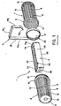
- - la figure 1 est une vue en perspective éclatée d'un support conforme à la présente invention;
- - la figure 2 est une vue en coupe longitudinale du support de la figure 1, à l'état assemblé et dans sa position d'utilisation, le crochet dudit support n'étant représenté que partiellement;
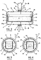
- - la figure 3 est une vue en coupe transversale selon III - III de la figure 2, la barquette renfermant le produit colorant hydrosoluble se trouvant dans sa position d'équilibre stable;
- - la figure 4 est une vue analogue à la figure 3, à la différence que la barquette est représentée dans sa position d'équilibre instable;
- - la figure 5 est une vue en coupe longitudinale d'une barquette conforme à une variante de réalisation; et
- - la figure 6 est une vue de dessus de la barquette de la figure 5.
- - Figure 1 is an exploded perspective view of a support according to the present invention;
- - Figure 2 is a longitudinal sectional view of the support of Figure 1, in the assembled state and in its position of use, the hook of said support being shown only partially;
- - Figure 3 is a cross-sectional view along III - III of Figure 2, the tray containing the water-soluble coloring product being in its stable equilibrium position;
- - Figure 4 is a view similar to Figure 3, with the difference that the tray is shown in its unstable equilibrium position;
- - Figure 5 is a longitudinal sectional view of a container according to an alternative embodiment; and
- - Figure 6 is a top view of the tray of Figure 5.
En se référant aux figures 1 à 4 du dessin, on voit que l'on a représenté par 1 dans son ensemble, un support constitué, d'une part, par une cage ajourée 2 destinée à renfermer un produit hydrosoluble 3, à action désodorisante et désinfectante, ledit produit 3, qui par ailleurs renferme une substance colorante, étant contenu dans une barquette 4, et, d'autre part, par un crochet 5 destiné à permettre la suspension de la cage 2 sur le rebord d'une cuvette de toilettes.Referring to Figures 1 to 4 of the drawing, we see that there is shown by 1 as a whole, a support consisting, on the one hand, of an
La cage 2 est formée par l'assemblage de deux demi-cages 6, 7; elle présente une forme générale cylindrique et comporte des barreaux 8 parallèles à son axe, raccordes à chaque extrémité de la cage 2, à un disque 9, et, dans la zone du plan médian tranversal de la cage 2, à l'un des deux demi-anneaux de raccordement 10, 11 que comporte chaque demi-cage 6, 7 respectivement. La cage 2 est également munie d'anneaux 12 coaxiaux, régulièrement espacés le long de ladite cage 2 et disposés perpendiculairement à l'axe de cette dernière.The
Comme on peut le voir notamment sur la figure 2, le demi-anneau de raccordement 10 de la demi-cage 6 comporte extérieurement, le long de sa bordure libre, un jonc périphérique 13, tandis que le demi-anneau de raccordement 11 de la demi-cage 7 comporte intérieurement, également le long de sa bordure libre, une gorge annulaire 14. De cette façon, les demi-cages 6, 7 peuvent être solidarisées l'une à l'autre grâce à l'encliquetage du jonc 13 à l'intérieur de la gorge 14.As can be seen in particular in FIG. 2, the connection half-
De plus, chaque demi-anneau 10, 11 forme, au voisinage de sa jonction avec la paroi latérale ajourée de la demi-cage associée 6, 7 respectivement, un bourrelet 15,16 respectivement, faisant saillie radialement par rapport à ladite paroi latérale ajourée. En position d'assemblage des demi-cages 6, 7, les bourrelets 15, 16 délimitent un espace annulaire 17 dont le rôle est indiqué ci-après.In addition, each half-
En outre, chaque disque d'extrémité 9 d'une demi-cage 6, 7 respectivement comporte, dirigé vers le centre de la demi-cage associée 6, 7 un bourrelet 18 ayant la forme d'une calotte sphérique d'axe confondu avec l'axe longitudinal de la cage 2. Le rôle de ces bourrelets 18, qui sont constitués ici par une déformation de la paroi des disques 9, est indiqué plus loin.In addition, each
Le crochet de suspension 5 se compose, d'une part, d'une partie en U 19 destinée à assurer la suspension du support 1, et, d'autre part, d'une partie qui supporte la cage ajourée 2, et qui consiste en un manchon de raccordement 20 destiné à coopérer avec les demi- anneaux 10, 11 des demi-cages 6, 7.The
La parttie en U 19 du crochet 5 comporte deux branches 19a, 19b reliées par une âme 19c. La branche 19a se raccorde au manchon 20 d'une façon sensiblement tangentielle; l'âme 19c vient se disposer de façon à surplomber le manchon 20 et la branche 19b, de plus faible longueur que la branche 19a, présente une extrémité libre 19d légèrement repliée en direction de la branche 19a de manière à faciliter la mise en place du support 1. Il est également possible de prévoir, au moulage, une zone de pliure de la branche 19a permettant de replier la partie 19 autour du manchon de raccordement 20, la partie 19d venant se placer à proximité de la jonction entre la branche 19a et ledit manchon 20. Il en résulte un encombrement réduit du crochet 5, simplifiant ainsi son conditionnement.The U-shaped
Le manchon de raccordement 20 comporte intérieurement une nervure 21, qui est interrompue dans le cas du support 1 représenté sur le dessin, ladite nervure 21 étant destinée à venir se placer dans l'espace annulaire 17 précité lors de l'encliquetage du manchon 20 sur l'anneau de raccordement constitué lors de l'assemblage des demi-cages 6, 7.The
Le récipient 4, en forme de parallélépipède rectangle allongé, comporte un fond 22 auquel se raccordent deux parois longitudinales opposées 23 et deux parois transversales opposées 24, ces dernières étant de forme sensiblement carrée. Ce récipient 4 constitue donc une barquette dans le fond de laquelle est coulé in situ le produit 3 qui est avantageusement constitué par une formulation contenant un colorant, ou un désinfectant tel que l'acide trichloro-cyanurique, ou les deux simultanément. Par ailleurs, la bordure supérieure libre de l'une des parois longitudinales 23 du récipient 4 présente une échancrure en U 25 de faible dimension.The container 4, in the shape of an elongated rectangular parallelepiped, has a
Chaque paroi transversale 24 comporte extérieurement une zone en creux 26 ayant la forme d'une calotte sphérique dont l'axe est perpendiculaire à l'axe longitudinale de symétrie du parallèlépipède que forme le récipient 4. En position d'assemblage du support 1, les zones en creux 26 reçovient les bourrelets de forme complémentaire 18 portés par la cage 2, de façon à permettre le montage pivotant du récipient 4 dans la cage 2, les bourrelets 18 jouant le rôle d'axes coopérant avec les zones 26 qui jouent le rôle de paliers.Each
Par allleurs, comme on peut le voir notamment sur la figure 2, les parois 24 comportent chacune intérieurement une nervure médiane 24a s'étendant depuis le fond 22 jusqu'au voisinage de la bordure libre du récipient 4, ces nervures 24a facilitant l'accrochage du produit 3 dans ledit récipient 4.By allleurs, as can be seen in particular in Figure 2, the
La fabrication et le montage en usine du support 1 est extrêmement simple; tous les éléments qui le composent sont obtenus par moulage d'une matière plastique les récipients 4, les crochets 5, les demi-cages 6, 7 étant réalisés, en polypropylène.The manufacture and assembly in the factory of the support 1 is extremely simple; all the elements which compose it are obtained by molding a plastic material, the containers 4, the
Le produit 3 est coulé à chaud en série dans les récipients 4. Une fois le produit 3 solidifié, on introduit chaque récipient 4 dans une demi-cage 6 ou 7 et on vient fixer à celle-ci l'autre demi-cage 7 ou 6; dans cette opération de montage, il est inutile de se préoccuper de la position relative des demi-cages 6, 7 et de la position que prend le récipient 4 à l'intérieur de la cage 2 ainsi constiuée. Ensuite, pour chaque ensemble ainsi constitué, on présente un crochet 5 à l'une des extrémités de la cage 2 et on fait coulisser son manchon 20 jusqu'à ce qu'il s'encliquette dans l'anneau de raccordement constitué par la réunion des demi-anneaux 10,11 de la cage 2. Il n'est nullement besoin non plus, lors de la mise en place de ce crochet 5, de se préoccuper de la position relative qu'il occupe par rapport à la cage 2.The
Lorsque le support 1 est en place dans une cuvette de toilettes, l'axe de la cage 2 étant alors disposé horizontalement, le récipient 4, par suite de son montage pivotant autour de cet axe et compte tenu du fait que le centre de gravité de l'ensemble récipient 4/ produit 3 se trouve à une distance non nulle dudit axe, tend à prendre l'une ou l'autre des positions d'équilibre représentées sur les figures 3 et 4 respectivement, ou une position voisine de ces positions d'équilibre en raison des frottements qui peuvent exister. Sur la figure 3, on a représenté le récipient 4 dans sa position d'équilibre stable, dans laquelle le fond 22 dudit récipient 4 se situe au-dessous de l'axe longitudinal de la cage 2, dans le plan parallèle audit axe; sur la figure 4, on a représenté la position d'équilibre instable dudit récipient 4, dans laquelle ledit fond 22 se situe au-dessus de l'axe précité, toujours dans un plan parallèle audit axe.When the support 1 is in place in a toilet bowl, the axis of the
On peut souligner que même si le récipient 4 ne contenait pas de produit 3, il aurait également naturellement tendance à prendre, lorsque la cage 2 est disposée avec son axe horizontal, l'une des positions des figures 3 et 4; en effet, du fait que le récipient 4 est un récipient ouvert, son centre de gravité ne se trouve pas sur l'axe de pivotement.It can be emphasized that even if the container 4 did not contain
Si, à l'intérieur de la cuvetté de toilettes, le récipient 4 se trouvé dans la position qu'il occupe sur la figure 3, lorsque la chasse d'eau est actionnée, l'eau de chasse se déverse à fort débit sur la cage 2 et elle pénètre, par les ouvertures de ladite cage 2 l'intérieur du récipient 4. Ce récipient se remplit alors d'eau fortement colorée, le trop-plein se déversant alors par dessus l'arête supérieure des parois 23 et 24 du récipient 4. L'eau colorée s'échappe alors par les ouvertures de la cage 2 et tombe dans la cuvette de toilettes. Lorsque le débit d'eau s'est arrêté, le récipient 4 reste rempli, à sa partie supérieure, d'eau colorée. Dans ces conditions, s'il se produit un dégouttage de la cage 2 et que les gouttes d'eau tombent dans le récipient 4, le trop-plein qui s'échappera alors de ce récipient 4 sera constitué par des gouttes d'une solution, certes colorée, mais de faible concentration, puisque provenant de la solution formée au moment de l'aspersion totale. Il n'y a donc pas de dégouttage du produit proprement-dit, dont on a vu qu'il conduit à la formation de taches, souvent très difficile à faire disparaître, sur la cuvette des toilettes.If, inside the toilet bowl, the container 4 is in the position it occupies in FIG. 3, when the flush is activated, the flushing water flows out at a high rate onto the
Si, au moment de la première utilisation du support 1, le récipient 4 se trouve dans la position qu'il occupe sur la figure 4, l'aspersion d'eau provoquera immédiatement le pivotement dudit récipient 4, pour le placer dans la position qu'il occupe sur la figure 3.If, at the time of the first use of the support 1, the container 4 is in the position it occupies in FIG. 4, the water spraying will immediately cause said container 4 to pivot, to place it in the position it occupies in FIG. 3.
Après la première utilisation du support de la présente invention, le récipient 4 est toujours placé dans la position correcte et peut fonctionner jusqu'à ce que tout le produit 3 ait été entraîné dans le fond de la cuvette, par suite des manoeuvres successives de la chasse d'eau.After the first use of the support of the present invention, the container 4 is always placed in the correct position and can operate until all the
En se référant maintenant aux figures 5 et 6 du dessin, on voit que l'on a désigné par 104, dans son ensemble, une seconde variante du récipient 4 du premier mode de réalisation. Le récipient 104 ne diffère du récipient 4 que par des détails de réalisation. Il présente en effet, comme le récipient 4, la forme d'un parallélépipède allongé, et comporte un fond 122 auquel se raccordent deux parois longitudinales 123 opposées et deux parois transversales 124 opposées.Referring now to Figures 5 and 6 of the drawing, it can be seen that there has been designated by 104, as a whole, a second variant of the container 4 of the first embodiment. The
Les zones en creux 126 pratiquées extérieurement dans les parois 124 présentent une forme conique dont l'axe est également confondu avec l'axe de pivotement du récipient 104 et qui sont destinés à coopérer avec des bourrelets de forme complémentaire prévus sur la cage associée.The recessed
Par ailleurs, le récipient 104, comporte intérieurement, deux nervures identiques 124a disposées dans le plan longitudinal médian du récipient 104 et présentant chacune la forme d'un triangle rectangle se raccordant, d'une part, au fond 122 et, d'autre part, à la paroi 124.Furthermore, the
Il est également prévu que le récipient 104 comporte deux nervures 127 de faible hauteur, disposées symétriquement par rapport au plan tranversal médian perpendiculaire à l'axe longitudinal du récipient 104, ces nervures 127 étant portees par le fond 122 et les deux parois longitudinales opposées 123 de la cage 104.It is also expected that the
On a également prévu de rigidifier les parois 123 en prévoyant sur chacune d'elles, une déformation vers l'extérieur 128 constituant une nervure médiane de rigidification.Provision has also been made to stiffen the
En outre, chacune des parois 123 comporte, au voisinage de sa jonction avec l'une des parois 124, un décrochement vers l'intérieur constituant une rainure 129 s'étendant depuis le fond 122 jusqu'au voisinage de l'arête supérieure de la paroi 123. Par ailleurs, les rainures 129 sont disposées d'une façon symétrique par rapport au plan transversal médian du récipient 104. De la sorte, le trop-plein de solution colorée que renfermera le récipient 104 pourra s'écouler à l'extérieur le long de ces rainures 129.In addition, each of the
Il est bien entendu que le mode de réalisation ci-dessus décrit n'est aucunement limitatif et pourra donner lieu à toutes modifications désirables, sans sortir pour cela du cadre de l'invention, comme délimité par les revendications suivantes.It is understood that the embodiment described above is in no way limiting and may give rise to any desirable modifications, without departing from the scope of the invention, as delimited by the following claims.
Claims (15)
Priority Applications (1)
| Application Number | Priority Date | Filing Date | Title |
|---|---|---|---|
| AT86402166T ATE39719T1 (en) | 1985-10-07 | 1986-10-02 | HOLDER FOR A PRODUCT, PARTICULARLY DYE, FOR HANGING ON THE EDGE OF A TOILET PAN. |
Applications Claiming Priority (2)
| Application Number | Priority Date | Filing Date | Title |
|---|---|---|---|
| FR8514809 | 1985-10-07 | ||
| FR8514809A FR2588298B1 (en) | 1985-10-07 | 1985-10-07 | PRODUCT SUPPORT, ESPECIALLY COLORING, FOR HANGING ON THE EDGE OF A TOILET BOWL |
Publications (2)
| Publication Number | Publication Date |
|---|---|
| EP0221800A1 EP0221800A1 (en) | 1987-05-13 |
| EP0221800B1 true EP0221800B1 (en) | 1989-01-04 |
Family
ID=9323579
Family Applications (1)
| Application Number | Title | Priority Date | Filing Date |
|---|---|---|---|
| EP86402166A Expired EP0221800B1 (en) | 1985-10-07 | 1986-10-02 | Support for a product, especially a colouring material, to be hooked to the rim of a toilet bowl |
Country Status (6)
| Country | Link |
|---|---|
| EP (1) | EP0221800B1 (en) |
| AT (1) | ATE39719T1 (en) |
| DE (2) | DE221800T1 (en) |
| ES (1) | ES2000002B3 (en) |
| FR (1) | FR2588298B1 (en) |
| GR (2) | GR880300044T1 (en) |
Families Citing this family (2)
| Publication number | Priority date | Publication date | Assignee | Title |
|---|---|---|---|---|
| FR2643665B1 (en) * | 1989-02-28 | 1991-06-21 | Oreal | METHOD FOR PLACING A SOLID WATER-SOLUBLE PRODUCT IN A TOILET BOWL AND DEVICE FOR CARRYING OUT SAID METHOD |
| KR102237401B1 (en) * | 2019-07-11 | 2021-04-07 | 서은영 | Apparatus to supply cleaning material for a toilet bowl |
Family Cites Families (5)
| Publication number | Priority date | Publication date | Assignee | Title |
|---|---|---|---|---|
| US3538520A (en) * | 1967-12-26 | 1970-11-10 | Madison Chem Corp | Lavatory sanitation bodies |
| NL6808754A (en) * | 1968-06-21 | 1969-12-23 | ||
| LU79505A1 (en) * | 1978-04-24 | 1979-11-07 | Globol Werk | CLOSET FLUSH WATER FAIRER |
| FR2429877A1 (en) * | 1978-06-27 | 1980-01-25 | Chiminter | AIR FRESHENER SUPPORT FOR TOILET BOWL |
| US4512041A (en) * | 1983-10-18 | 1985-04-23 | Tsai Tseng B | Dispensing device |
-
1985
- 1985-10-07 FR FR8514809A patent/FR2588298B1/en not_active Expired
-
1986
- 1986-10-02 DE DE198686402166T patent/DE221800T1/en active Pending
- 1986-10-02 ES ES86402166T patent/ES2000002B3/en not_active Expired
- 1986-10-02 AT AT86402166T patent/ATE39719T1/en not_active IP Right Cessation
- 1986-10-02 EP EP86402166A patent/EP0221800B1/en not_active Expired
- 1986-10-02 DE DE8686402166T patent/DE3661642D1/en not_active Expired
-
1988
- 1988-05-20 GR GR88300044T patent/GR880300044T1/en unknown
-
1989
- 1989-03-23 GR GR88400011T patent/GR3000011T3/en unknown
Also Published As
| Publication number | Publication date |
|---|---|
| FR2588298B1 (en) | 1988-01-08 |
| GR3000011T3 (en) | 1989-09-29 |
| FR2588298A1 (en) | 1987-04-10 |
| ES2000002B3 (en) | 1989-05-01 |
| ES2000002A4 (en) | 1987-06-01 |
| GR880300044T1 (en) | 1988-10-18 |
| EP0221800A1 (en) | 1987-05-13 |
| DE221800T1 (en) | 1987-09-03 |
| DE3661642D1 (en) | 1989-02-09 |
| ATE39719T1 (en) | 1989-01-15 |
Similar Documents
| Publication | Publication Date | Title |
|---|---|---|
| EP1642846B1 (en) | Assembly for simultaneously dispensing of two materials | |
| FR2563711A1 (en) | ASSEMBLY FOR THE PACKAGING AND APPLICATION OF A SUBSTANCE, IN PARTICULAR COSMETIC, IN THE SOLID FORM | |
| FR2593785A1 (en) | Two-piece pouring stopper | |
| FR2675120A1 (en) | BUCKET HAS RETAINED. | |
| EP0826322A1 (en) | Case for packaging a solid or semi-solid product which can be pulled out | |
| CA1047703A (en) | Support for water soluble stick in toilet flush tank_ | |
| EP0221800B1 (en) | Support for a product, especially a colouring material, to be hooked to the rim of a toilet bowl | |
| CA1106130A (en) | Deodorant support for toilet bowl | |
| FR2508871A1 (en) | GERBABLE AND EMBEDABLE BAC | |
| FR2532347A1 (en) | Device for dispensing water-soluble substances in a water flush. | |
| CH402635A (en) | Pouring spout for one container | |
| FR2474458A1 (en) | SYSTEM FOR CLEANING WATER-CLOSET BASINS CONSISTING OF A RECEPTACLE ARRANGED IN THE WATER TANK ASSOCIATED WITH THE BASIN | |
| EP0349409A1 (en) | Product support, especially a colouring product adapted to be hooked to the rim of a toilet bowl | |
| FR2643665A1 (en) | PROCESS FOR PLACING A WATER-SOLUBLE SOLID PRODUCT IN A TOILET BOWL AND DEVICE FOR CARRYING OUT SAID METHOD | |
| EP2255615B1 (en) | Device for preparing cottage cheese inside a strainer | |
| FR2753340A1 (en) | DEVICE FOR CONTAINING AND SUSPENDING A LOAD OF A MATERIAL, FOR EXAMPLE FLOWER POT | |
| EP0842599A1 (en) | Horticultural container | |
| CH637718A5 (en) | METHOD FOR MANUFACTURING A DEODORIZING AND DISINFECTANT PRODUCT SUPPORT FOR TOILET BOWLS AND DEVICE FOR IMPLEMENTING SAME. | |
| CH628384A5 (en) | SUPPORT FOR A BLOCK OF DEODORIZING AND DISINFECTANT PRODUCT FOR TOILET BOWLS. | |
| FR2589498A1 (en) | Device for distributing water-soluble products in a water-flushing device | |
| FR2755423A1 (en) | PACKAGING AND DISPENSING BOX FOR ANIMAL FEED | |
| FR2505902A1 (en) | Disinfectant support for WC cistern - comprises hook incorporating syphon which carries reservoir containing disinfectant block | |
| FR2753339A1 (en) | Container, for a charge of material and to be suspended | |
| CA1132489A (en) | Method for the fabrication of a deodorant-disinfectant holder for toilet bowls and holder made by this method | |
| EP1064841B1 (en) | Plant container assembly with water reservoir |
Legal Events
| Date | Code | Title | Description |
|---|---|---|---|
| PUAI | Public reference made under article 153(3) epc to a published international application that has entered the european phase |
Free format text: ORIGINAL CODE: 0009012 |
|
| 17P | Request for examination filed |
Effective date: 19861003 |
|
| AK | Designated contracting states |
Kind code of ref document: A1 Designated state(s): AT BE CH DE ES FR GB GR IT LI NL SE |
|
| ITCL | It: translation for ep claims filed |
Representative=s name: JACOBACCI CASETTA & PERANI S.P.A. |
|
| TCAT | At: translation of patent claims filed | ||
| DET | De: translation of patent claims | ||
| 17Q | First examination report despatched |
Effective date: 19880609 |
|
| GRAA | (expected) grant |
Free format text: ORIGINAL CODE: 0009210 |
|
| AK | Designated contracting states |
Kind code of ref document: B1 Designated state(s): AT BE CH DE ES FR GB GR IT LI NL SE |
|
| REF | Corresponds to: |
Ref document number: 39719 Country of ref document: AT Date of ref document: 19890115 Kind code of ref document: T |
|
| ITF | It: translation for a ep patent filed |
Owner name: JACOBACCI & PERANI S.P.A. |
|
| GBT | Gb: translation of ep patent filed (gb section 77(6)(a)/1977) | ||
| REF | Corresponds to: |
Ref document number: 3661642 Country of ref document: DE Date of ref document: 19890209 |
|
| REG | Reference to a national code |
Ref country code: GR Ref legal event code: FG4A Free format text: 3000011 |
|
| REG | Reference to a national code |
Ref country code: FR Ref legal event code: TP |
|
| PLBE | No opposition filed within time limit |
Free format text: ORIGINAL CODE: 0009261 |
|
| STAA | Information on the status of an ep patent application or granted ep patent |
Free format text: STATUS: NO OPPOSITION FILED WITHIN TIME LIMIT |
|
| 26N | No opposition filed | ||
| REG | Reference to a national code |
Ref country code: FR Ref legal event code: TP |
|
| NLS | Nl: assignments of ep-patents |
Owner name: S.C. JOHNSON & SON, INC. TE RACINE, WISCONSIN, VER |
|
| ITPR | It: changes in ownership of a european patent |
Owner name: CESSIONE;S.C. JOHNSON & SON INC. |
|
| REG | Reference to a national code |
Ref country code: CH Ref legal event code: PUE Owner name: S. C. JOHNSON & SON, INC. |
|
| PGFP | Annual fee paid to national office [announced via postgrant information from national office to epo] |
Ref country code: GR Payment date: 19910926 Year of fee payment: 6 Ref country code: AT Payment date: 19910926 Year of fee payment: 6 |
|
| PGFP | Annual fee paid to national office [announced via postgrant information from national office to epo] |
Ref country code: GB Payment date: 19910927 Year of fee payment: 6 |
|
| PGFP | Annual fee paid to national office [announced via postgrant information from national office to epo] |
Ref country code: CH Payment date: 19911014 Year of fee payment: 6 |
|
| PGFP | Annual fee paid to national office [announced via postgrant information from national office to epo] |
Ref country code: ES Payment date: 19911016 Year of fee payment: 6 |
|
| PGFP | Annual fee paid to national office [announced via postgrant information from national office to epo] |
Ref country code: DE Payment date: 19911018 Year of fee payment: 6 |
|
| PGFP | Annual fee paid to national office [announced via postgrant information from national office to epo] |
Ref country code: SE Payment date: 19911028 Year of fee payment: 6 |
|
| PGFP | Annual fee paid to national office [announced via postgrant information from national office to epo] |
Ref country code: FR Payment date: 19911030 Year of fee payment: 6 |
|
| ITTA | It: last paid annual fee | ||
| PGFP | Annual fee paid to national office [announced via postgrant information from national office to epo] |
Ref country code: NL Payment date: 19911031 Year of fee payment: 6 |
|
| PGFP | Annual fee paid to national office [announced via postgrant information from national office to epo] |
Ref country code: BE Payment date: 19911113 Year of fee payment: 6 |
|
| REG | Reference to a national code |
Ref country code: GB Ref legal event code: 732 |
|
| PG25 | Lapsed in a contracting state [announced via postgrant information from national office to epo] |
Ref country code: GB Effective date: 19921002 Ref country code: AT Effective date: 19921002 |
|
| PG25 | Lapsed in a contracting state [announced via postgrant information from national office to epo] |
Ref country code: SE Effective date: 19921003 Ref country code: ES Free format text: LAPSE BECAUSE OF EXPIRATION OF PROTECTION Effective date: 19921003 |
|
| PG25 | Lapsed in a contracting state [announced via postgrant information from national office to epo] |
Ref country code: LI Effective date: 19921031 Ref country code: CH Effective date: 19921031 Ref country code: BE Effective date: 19921031 |
|
| BERE | Be: lapsed |
Owner name: SC JOHNSON & SON INC. Effective date: 19921031 |
|
| PG25 | Lapsed in a contracting state [announced via postgrant information from national office to epo] |
Ref country code: GR Free format text: THE PATENT HAS BEEN ANNULLED BY A DECISION OF A NATIONAL AUTHORITY Effective date: 19930430 |
|
| PG25 | Lapsed in a contracting state [announced via postgrant information from national office to epo] |
Ref country code: NL Effective date: 19930501 |
|
| GBPC | Gb: european patent ceased through non-payment of renewal fee |
Effective date: 19921002 |
|
| NLV4 | Nl: lapsed or anulled due to non-payment of the annual fee | ||
| PG25 | Lapsed in a contracting state [announced via postgrant information from national office to epo] |
Ref country code: FR Effective date: 19930630 |
|
| REG | Reference to a national code |
Ref country code: CH Ref legal event code: PL |
|
| PG25 | Lapsed in a contracting state [announced via postgrant information from national office to epo] |
Ref country code: DE Effective date: 19930701 |
|
| REG | Reference to a national code |
Ref country code: ES Ref legal event code: PC2A Owner name: S.C. JOHNSON & SON, INC. |
|
| REG | Reference to a national code |
Ref country code: FR Ref legal event code: ST |
|
| REG | Reference to a national code |
Ref country code: GR Ref legal event code: MM2A Free format text: 3000011 |
|
| EUG | Se: european patent has lapsed |
Ref document number: 86402166.2 Effective date: 19930510 |
|
| REG | Reference to a national code |
Ref country code: ES Ref legal event code: FD2A Effective date: 19990601 |
|
| PG25 | Lapsed in a contracting state [announced via postgrant information from national office to epo] |
Ref country code: IT Free format text: LAPSE BECAUSE OF NON-PAYMENT OF DUE FEES Effective date: 20051002 |